+ Allow you to query the temperature sensor via a HTTP Request. A JSON representation of the device will be returned.
As of now the only available devices are Type28 and Type7E...
Type28 is the temperature probe and Type7E is the environmental sensor.
To enable this you will need to set the AppData/Cinema/WebServer/Port registry key. The JNIOR will need to be rebooted after this key has been changed. In this example I chose 8081. Port 80 or 443 is normally the default web server port. This web server port is an additional web server that cinema is hosting to handle these types of requests.
The biggest one is that series 4 JNIORs will use the WebSockets protocol during an Update Project. WebSockets use the HTTP port, which is normally port 80. This port is usually forwarded so that you can get to the WEB UI. FTP and Telnet are not used with Series 4 JNIORs.
You can also open multiple update projects at the same time. You can push one setup to a set of JNIORs and then push a different setup to a different set of JNIORs at the same time. Care must be taken to not push conflicting updates to the same JNIOR.
Multiple snapshots can be taken at the same time.
This version also allows you to select multiple JNIORs in the Beacon tab. Right clicking and selecting an action from the popup menu will apply to all of the selected JNIORs. This is especially useful if you want to take snapshots of all of your units at once.
You can right click on a unit in beacon to get the Network Capture.
This post will go over how to create an entity in Home Assistant that will keep track of a JNIOR temperature probe using MQTT.
Setup MQTT on the JNIOR
Before beginning to setup Home Assistant, you’ll want to make sure that you have MQTT setup on your JNIOR. Here is a post you can follow to setup MQTT on the JNIOR.
Setup Home Assistant
Now to start configuring Home Assistant, you’ll need to make sure you have a working setup of it. Here is the installation walkthrough on Home Assistant’s website. Once you have successfully setup a working setup of Home Assistant, you should be able to access its Configuration Web Page at homeassistant.local:8123 in a Web Browser. It should look like this when you access it.
Add MQTT Integration
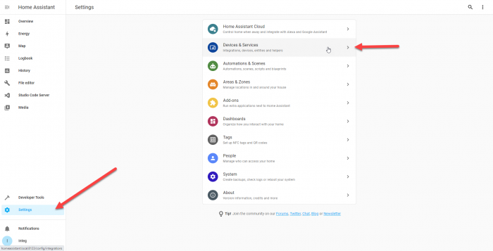
After you’ve setup Home Assistant, you can now begin to configure Home Assistant to monitor a JNIOR Output. To do this the first thing we need to do is setup the MQTT integration. To do this you’ll go to your settings and select Devices and Services.
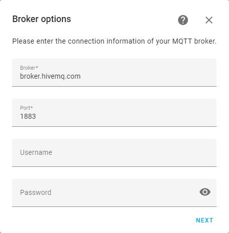
Once there, select Add Integration at the bottom of the page and you’ll search for the MQTT integration and add it to your current integrations. Once MQTT is added to your integrations, you’ll then need to configure it to use the same MQTT Broker as your JNIOR device. Here we are using broker.hivemq.com.
Get File Editor Add-on
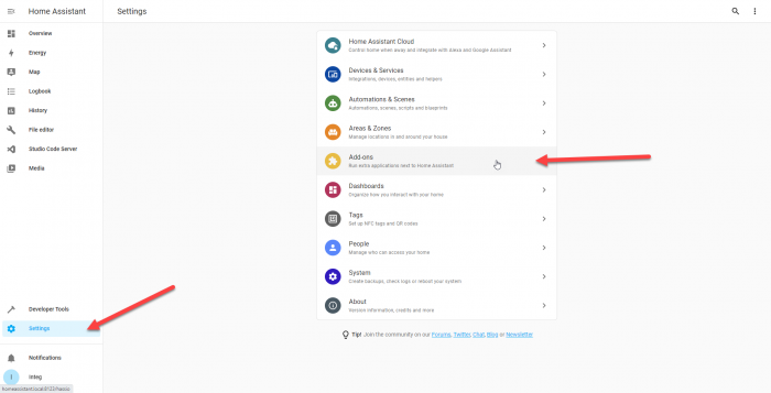
Select next and finish configuring the MQTT integration. After its completed, the next thing we can do is setup an MQTT Sensor Entity. This will represent an on/off status of our JNIOR Output. To do this, we are going to need to get an add-on for Home Assistant. To do this we will select Setting again and go to the Add-ons.
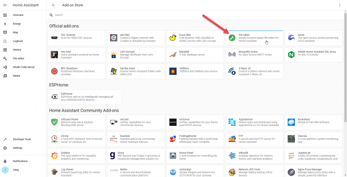
Once in Add-ons, you’ll look for the add-on called File Editor. You’ll select that add-on and install it. (Adding it to your sidebar in its installation settings is helpful also.) This is needed to edit your configuration.yaml file. What is configuration. yaml? The configuration.yaml file is the main YAML file used by Home Assistant to gather all of the information about the users desired configuration. In this file we will define the MQTT Sensor, and we need the file editor add-on to do so.
Configure .yaml File
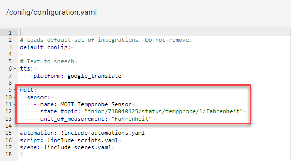
Once the File Editor add-on is installed we’ll go to it using the sidebar in Home Assistant. The File Editor will display all the files in Home Assistant, and the one we are interested in is the configuration.yaml file explained earlier. In this file we are going to add the MQTT Sensor platform inside it. Here is a picture of a configuration.yaml file after adding the temperature probe as an MQTT sensor.
NOTE: If using the example above, make sure to replace the serial number of the JNIOR above with your JNIOR’s serial number.
# Loads default set of integrations. Do not remove.
default_config:

# Text to speech
tts:
  - platform: google_translate

mqtt:
  sensor:
    - name: MQTT_Tempprobe_Sensor
      state_topic: "jnior/718040125/status/tempprobe/1/fahrenheit"
      unit_of_measurement: "Fahrenheit"

automation: !include automations.yaml
script: !include scripts.yaml
scene: !include scenes.yaml
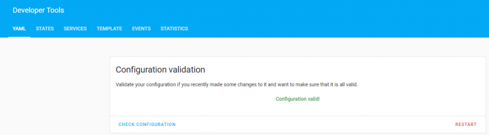
Once this is added to your configuration.yaml file, head over to the developer tools above the settings option in the Home Assistant sidebar. On this page click the ‘check configuration’ button, and if the configuration is valid, you’ll then select the ‘restart’ button.
Setup Home Assistant Dashboard
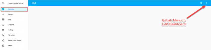
Once Home Assistant has restarted, we can now go to the overview page of Home Assistant and edit our Dashboard. In the Dashboard we are going to click on the kebab menu and select edit Dashboard. This will allow us to add entities that will display the statuses of our JNIOR’s I/O sensors.
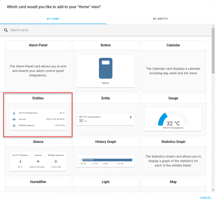
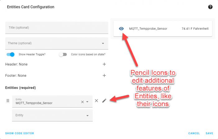
With the Dashboard Editor open, we’ll add a new card to the Dashboard. The card we want to add is the Entities Card, as this will let us display the MQTT Sensors we declared in the configuration.yaml file while leaving room to add more. This will also allow us to show how our JNIOR’s temperature probe is being monitored.
Inside in the Entities card, we’ll select the MQTT Sensor we made. Optionally, you can change certain attributes of the card by clicking the pencil icon next to the entity.
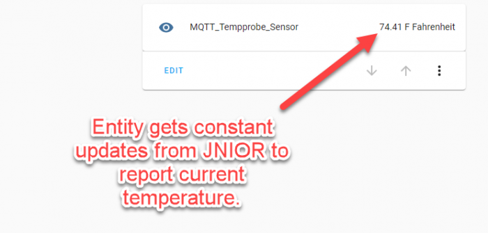
Save this Card Configuration, and you should now have a dashboard with your entity. When the JNIOR’s temperature probe changes, so will your entity on your homepage!
This post will go over how to create an entity in Home Assistant that will keep track of a JNIOR Output using MQTT.
Setup MQTT on the JNIOR
Before beginning to setup Home Assistant, you’ll want to make sure that you have MQTT setup on your JNIOR. Here is a post you can follow to setup MQTT on the JNIOR.
Setup Home Assistant
Now to start configuring Home Assistant, you’ll need to make sure you have a working setup of it. Here is the installation walkthrough on Home Assistant’s website. Once you have successfully setup a working setup of Home Assistant, you should be able to access its Configuration Web Page at homeassistant.local:8123 in a Web Browser. It should look like this when you access it.
Add MQTT Integration
After you’ve setup Home Assistant, you can now begin to configure Home Assistant to monitor a JNIOR Output. To do this the first thing we need to do is setup the MQTT integration. To do this you’ll go to your settings and select Devices and Services.
Once there, select Add Integration at the bottom of the page and you’ll search for the MQTT integration and add it to your current integrations. Once MQTT is added to your integrations, you’ll then need to configure it to use the same MQTT Broker as your JNIOR device. Here we are using broker.hivemq.com.
Get File Editor Add-on
Select next and finish configuring the MQTT integration. After its completed, the next thing we can do is setup an MQTT Binary Sensor Entity. This will represent an on/off status of our JNIOR Output. To do this, we are going to need to get an add-on for Home Assistant. To do this we will select Setting again and go to the Add-ons.
Once in Add-ons, you’ll look for the add-on called File Editor. You’ll select that add-on and install it. (Adding it to your sidebar in its installation settings is helpful also.) This is needed to edit your configuration.yaml file. What is configuration. yaml? The configuration.yaml file is the main YAML file used by Home Assistant to gather all of the information about the users desired configuration. In this file we will define the MQTT Binary Sensors, and we need the file editor add-on to do so.
Configure .yaml File
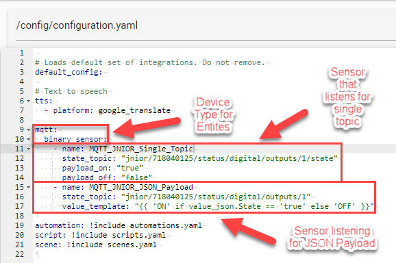
Once the File Editor add-on is installed we’ll go to it using the sidebar in Home Assistant. The File Editor will display all the files in Home Assistant, and the one we are interested in is the configuration.yaml file explained earlier. In this file we are going to add the MQTT Binary Sensor platform inside it. With the MQTT application on the JNIOR, topics on the Broker can be updated two different ways. The first is by updating a specific topic on the broker, and the other is using a JSON payload to update multiple topics at once. To show both ways, here is a picture of a configuration.yaml file after adding both ways to it. (This setup will be looking at Output 1 on the JNIOR, since in the state_topic lines it specifies Output 1)
NOTE: If using the example above, make sure to replace the serial number of the JNIOR above with your JNIOR’s serial number.
# Loads default set of integrations. Do not remove.
default_config:

# Text to speech
tts:
  - platform: google_translate

mqtt:
  binary_sensor:
    - name: MQTT_JNIOR_Single_Topic
      state_topic: "jnior/718040125/status/digital/outputs/1/state"
      payload_on: "true"
      payload_off: "false"
    - name: MQTT_JNIOR_JSON_Payload
      state_topic: "jnior/718040125/status/digital/outputs/1"
      value_template: "{{ 'ON' if value_json.State == 'true' else 'OFF' }}"

automation: !include automations.yaml
script: !include scripts.yaml
scene: !include scenes.yaml
Once this is added to your configuration.yaml file, head over to the developer tools above the settings option in the Home Assistant sidebar. On this page click the ‘check configuration’ button, and if the configuration is valid, you’ll then select the ‘restart’ button.
Setup Home Assistant Dashboard
Once Home Assistant has restarted, we can now go to the overview page of Home Assistant and edit our Dashboard. In the Dashboard we are going to click on the kebab menu and select edit Dashboard. This will allow us to add entities that will display the statuses of our JNIOR’s I/O sensors.
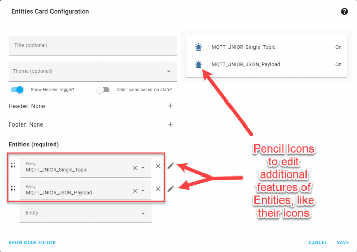
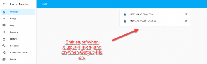
With the Dashboard Editor open, we’ll add a new card to the Dashboard. The card we want to add is the Entities Card, as this will let us display both MQTT Binary Sensors we declared in the configuration.yaml file. This will allow us to show how our JNIOR’s output is being monitored.
Inside in the Entities card, we’ll select the two MQTT Binary Sensors we made. In this example I also edit each of the entities to use different icons. This is optional, but you can change certain attributes of the card by clicking the pencil icon next to either entity.
Save this Card Configuration, and you should now have a dashboard with your entities. When the JNIOR’s output changes, so will your entities on your homepage! (Depending on if you chose the JSON Payload, Single_Topic, or both in the JNIOR’s MQTT application, only one may change.)
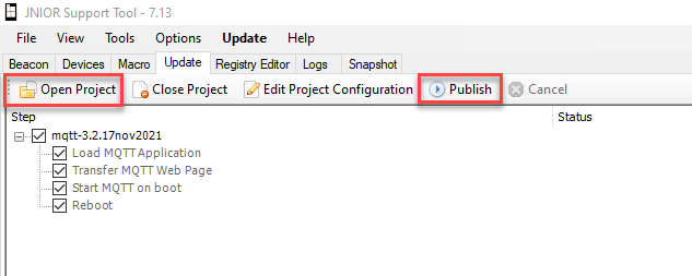
This post will go over installing MQTT onto a JNIOR, and then connecting to an MQTT Broker.
To start, download the JNIOR Support Tool and MQTT update project if you haven’t already. You’ll run the JNIOR Support Tool once its installed, and then go to the update tab. Here you’ll click ‘open project’ and select the MQTT update project. (do not unzip before opening in the support tool) Once its opened in the support tool you’ll select ‘publish’ and in the dialog box select the JNIOR you want to publish to and hit okay.
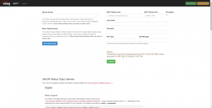
Once this is complete, you’ll want to go to the JNIOR web page for MQTT by going to a web browser and entering your JNIOR’s IP followed by /mqtt. (For example if your JNIOR’s IP is 10.0.0.110, in your web browser you would to go the URL 10.0.0.110/mqtt.) The webpage will look like this.
Once on this page, all you need to do is enter an MQTT Broker Host and its Port. You can use a Broker you already have, or if you don’t have one there are public Brokers that you can use. (Examples are test.mosquitto.org or https://www.hivemq.com/public-mqtt-broker which have their Host Names and Port Values on those pages.) You’ll save these changes, and afterward click the connect button. If the Status says connected, then MQTT is all setup on the JNIOR! If not, make sure you entered the correct settings for your Broker, and saved them before trying to connect.
The JNIOR is used in a variety of industries. Here the JNIOR is used in a clean energy solution, a residential Solar installation. This solar installation went live in the evening of July 7th, 2022. This is the second solar installation for this owner. The previous installation generated power for over a decade. It is still in operation but for a new owner.
How?
The JNIOR is tasked with communicating with the four inverters to collect the amount of power that they produce. Once every 10 seconds the application on the JNIOR sequentially communicates with each inverter to request the current power, daily yield and total yield. The communication is done via MODBUS TCP. Once the data is read, it is tucked away in 2 locations as individual reading and totalized. The data is stored in the registry as a system key that is used for real-time reporting. The data is also stored in a readings.dat log file. This file is moved to the flash filesystem at the end of every day for historical analysis. Only the previous 7 days are maintained in the flash filesystem. The files are numbered by the day of the week to ensure that Sunday overwrites last Sunday, Monday overwrites last Monday and so on.
The real-time data is served from the registry using a php script that generates a JSON format. That JSON response is requested and consumed by a linux server that is responsible for collecting and storing that data in a MYSQL database for long term storage.
Why?
Fun! While the data can be used to check that the power company is paying you for the kWhs generated beyond what is consumed by the house, this page is generally watched as a sort of game to see how days throughout the year stack up against each other.
While INTEG does not have a Home Assistant integration for the JNIOR, you can use the MQTT Integration to work with the JNIOR and Home Assistant quite easily. The MQTT Binary Sensor platform and MQTT Sensor platform can allow you to setup MQTT Sensors to monitor values on the JNIOR. Home Assistant can also publish topics to the MQTT Broker that the JNIOR is subscribed to.
With the release of JANOS 2.2, the bundled software that comes with JNIORs now have their own webpages! You can access them by going to a web browser and in the URL enter the JNIOR’s IP with ‘/bundled’ after it. As stated before, to access these web pages though you’ll need JANOS version 2.2 or later to access them. Here is a link that briefly goes over the Bundled Software Web Pages. Let us know what you think of it!
Web Pages have been added for Bundled Software Applications! These web pages have been implemented to make configuring the Bundled Software easier. This post will go over the different tabs the Bundled Software Pages have.
To start, there are 5 tabs available on the Bundled Software Pages. Other then the On Boot page, each tab should display different registry settings to configure a different application in the Bundled Software.
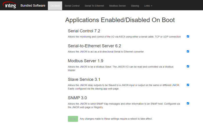
On Boot Page
The On Boot tab is the opening tab when the Bundled Software Pages are loaded. Instead of letting you edit the registry keys of one of the applications like the other tabs, this page allows you to set which Bundled Software Applications will run on boot. Keep in mind that when setting one of the these applications to not start on boot, you won’t be able to access that applications tab in the Bundled Software Pages until its enabled again.
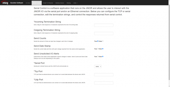
Serial Control
Serial Control can accept one or more connections from an external device and this connection can be over the serial port and/or the Ethernet port. The Serial Control tab allows you to edit the registry keys of Serial Control from the web page. Below is a quick explanation for each field.
Incoming Termination String – Sets the string that Serial Control looks for at the end of each message sent to it to know if that is the end of message being sent.
Outgoing Termination String – Sets the string that Serial Control adds to the end of each message it sends. The external device being sent to needs to know to look for this Outgoing Termination String.
Send Counts – Determines if the JNIOR reports each time an input changes to the external device connected through the Serial Control Connection.
Send Date Stamp – Determines if each report of an I/O change on the JNIOR reported through the Serial Control Connection gets appended with the current data and time.
Send Unsolicited I/O Alerts – Determines if any Alert such as I/O Counts or Date Stamps should be allowed through the Serial Control Connection.
Serial Port – Sets the Serial connection that Serial Control connects on.
TCP Port – Sets the TCP port that Serial Control connects on.
UDP Port – Sets the TCP port that Serial Control connects on.
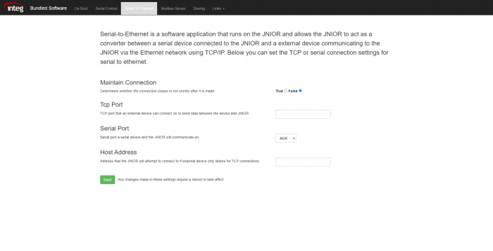
Serial-to-Ethernet
Serial-to-Ethernet lets you setup a connection between a device that can communicate via ethernet and a device that can only connect serially. The web page allows you to configure the port for the ethernet connection, the serial port of the serial connection, the host address of the device that the JNIOR will attempt to connect to if the external device only listens for TCP connections, and if the connection is maintained after being established.
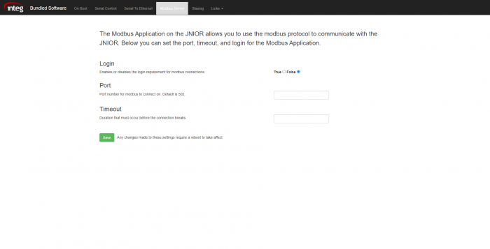
Modbus
Modbus lets you setup a connection to the JNIOR using the Modbus Protocol. The Modbus tab on the Bundled Software Pages allows you to setup the port the Modbus Protocol uses, if login is required, and the amount of time in seconds without communication on the Modbus connection for it to timeout.
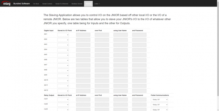
Slaving
Slaving lets you control the I/O on one JNIOR by monitoring the I/O of another. There are two tables on the Slaving tab, one for inputs and the other for outputs. Each input and output and on the JNIOR will be displayed in these tables, and from there can be set the I/O point they are slaved to, followed by the information of the external JNIOR that has that I/O point.
This release was issued to support manufacturing and component changes forced by supply chain issues. Because of this, an update to the OS was required to handle this change. Units made June 22nd, 2022 or later will NOT be able to roll back to earlier version of JANOS.
Corrected bug in creating multidimensional arrays
Improved DEFLATE compression performance with binary files
Corrected issue with ‘%’ sign when logging to the syslog
Fixed dropped serial character when port is closed
We have released JANOS v1.9 which has several changes and bug fixes. Most notably with TCP packet generation. While it is not wrong to send data in multiple TCP packets, many devices incorrectly implement TCP clients and fail when this case arises. This version adjusted the release of socket data to reduce the chances that a message might be split across separate TCP packets. This had been a recent issue with some MODBUS client devices.
Added support for Reverse LLMNR allowing network scanners to label IP addresses with hostnames
Adjusted the release of socket data to reduce the chances that a message might be split across separate TCP packets
Corrected Sockets race condition that caused occasional reception delays and blocking
Fixed the incorrect signed display of large input counter values in JRMON and JMP Protocol
Adds a BEACON announcement in the event of an IP conflict
Improved NONCE management eliminating possible issues in the presence of port scanners
Eliminated chance of buffer overrun occurring in FTP transfer
Beacon REBOOT now works in all cases
Eliminated potential difficulty in obtaining network capture file
We have released JANOS v1.8 which adds the JMP Protocol. The JANOS Management Protocol (JMP) is essentially the JSON message interface utilized by JANOS Websockets. The JMP Protocol has been exposed on its own TCP/IP port. This encloses the JSON messaging in a JSON array along with the JSON Object length making reception of the messages easy. The JMP Protocol will be used by the QSC Q-SYS JNIOR component.
Implements the JANOS Management Protocol JMP
Adds "Block" command to JSON interfaces
Web Server limits the effects of extremely slow connections.
--- Bundled --- FTP Client JBakup MODBUS Server 1.9.268 UPDATED Serial Control 7.2.47 UPDATED Serial To Ethernet 6.2.70 UPDATED Slaving Service 3.1.120 UPDATED SNMP 3.1.498 UPDATED Bundled Web Pages ADDED
All-In-One 211215 December 15, 2021
This Update was pushed to support manufacturing and the supply chain issues brought on by COVID-19. Component workarounds were needed and a bump to the OS was required to support those component changes. Units built after this date will not be able to roll back to previous versions of the OS.
--- Bundled --- FTP Client JBakup ADDED MODBUS Server 1.7.236 Serial Control 7.0.31 Serial To Ethernet 6.1.53 UPDATED Slaving Service 2.0.104 SNMP 3.1.667 Tasker REMOVED [Has its own installer]
All-In-One 210304 March 4, 2021
--- Core ---
  JANOS                2.0 build 1.0   UPDATED
  DCP                  3.0.1           UPDATED (moved from flash/www.zip to flash/www/config/zip)

--- Bundled ---
  FTP Client
  MODBUS Server        1.7.236
  Serial Control       7.0.31
  Serial To Ethernet   6.0.48
  Slaving Service      2.0.104
  SNMP                 3.1.667
  Tasker               6.0.1601
  Task Manager         7.0.351
All-In-One 210202 February 2, 2021
--- Core ---
  JANOS                2.0        UPDATED
  DCP                  2.4

--- Bundled ---
  FTP Client
  MODBUS Server        1.7.236
  Serial Control       7.0.31     UPDATED
  Serial To Ethernet   6.0.48
  Slaving Service      2.0.104    UPDATED
  SNMP                 3.1.667    UPDATED
  Tasker               5.0.1505   ADDED
  Task Manager         7.0.351
All-In-One 200501 May 1, 2020
--- Core ---
  JANOS                1.9            UPDATED
  DCP                  2.4

--- Bundled ---
  FTP Client
  MODBUS Server        1.7.236
  Serial Control       5.0.122.1501
  Serial To Ethernet   6.0.48
  Slaving Service      1.5.1810.225
  SNMP                 2.6.532        UPDATED
  Task Manager         7.0.351
All-In-One 200203 February 3, 2020
--- Core ---
  JANOS                1.9   UPDATED
  DCP                  2.4   UPDATED

--- Bundled ---
  FTP Client
  MODBUS Server        1.7.236
  Serial Control       5.0.122.1501
  Serial To Ethernet   6.0.48
  Slaving Service      1.5.1810.225
  SNMP                 2.4.1.494
  Task Manager         7.0.351
All-In-One 190618 June 18, 2019
--- Core ---
  JANOS                1.8
  DCP                  2.3

--- Bundled ---
  FTP Client
  MODBUS Server        1.7.236
  Serial Control       5.0.122.1501
  Serial To Ethernet   6.0.48
  Slaving Service      1.5.1810.225
  SNMP                 2.4.1.494
  Task Manager         7.0.351
We offerSeries 4 JNIORs that are made to be a great drop-in replacement for Series 3 JNIORs.
If you have a Series 3 JNIOR and are looking for a replacement, they unfortunately hit the end of life in 2015 and we no longer offer them. Series 4 JNIORs are essentially an improved version of the Series 3 JNIOR that offer improved hardware, more applications, and more built-in functionality. Most Series 3 applications have been modified to run on the Series 4 JNIORs as well, but the dimensions and footprint of the Series 3 JNIOR are the same as the Series 4 though.
Here are just a few of the improvements implemented from the Series 3 to Series 4:
A faster processor allows for quicker responses from applications running on the JNIOR and quicker reboots for the JNIOR.
The Model 410 JNIORs have RS-485 capabilities for their serial connections.
Applications such as Tasker, Analog Presets, MQTT, Grapher, and DMX provide new functionality for the JNIOR to use.
Easy-to-use configuration pages through web browsers provide more ways to make customizing your JNIOR simpler, such as a folder tab to view files on the JNIOR.
Series 4 JNIORs can capture network traffic between the JNIOR and other devices to help investigate and troubleshoot all data being communicated with it.
If you have a Series 3 JNIOR and are looking to replace or upgrade to a Series 4 JNIOR, let us know and we’ll help you transition your setup!
Using the JNIOR should be a smooth process, with only having to connect an Ethernet cord to your network and finding it in the JNIOR support tool. Unfortunately, nothing always goes perfectly, and maybe you aren’t able to access your JNIOR via beacon or an internet browser. Connecting to a Series 3 JNIOR serially is a great way to troubleshoot when it’s no longer responding correctly. This post will briefly go over how the JNIOR can be connected serially to access and hopefully fix this issue.
To access the JNIOR serially, a serial cable needs to be connected between the RS-232 port on the JNIOR and your computer. If you don’t have a serial port on your computer, you may need a serial to USB cable instead. Once that is connected, you can then open a command line prompt (You can open an easy-to-use command line from the support tool under the Tools Tab.) and access the serial connection. When doing this, make sure that the settings for the Serial Connection match what your JNIORs are. If you can’t check, the default settings for the connection are:
Baud Rate: 115200
DataBits: 8
StopBits: 1
Parity: None
Once you have set the correct serial settings, you should be able to hit connect and access the JNIOR via the command line! If by chance you are trying to change the JNIOR’s IP because it’s using one that doesn’t work with your local networks IP, you can change the IP of a JNIOR by using the ‘ipconfig’ command. Simply enter ‘ipconfig -a’ followed by a space and the IP address you are trying to change the JNIOR to. For example, if you are trying to change the IP address to 10.0.0.201, you would use this in the command line: ‘ipconfig -a 10.0.0.201’.
When setting up a connection from Cinema Server to a JNIOR, there are multiple ways to create that connection. This post will go through different options, and help you determine the connection that benefits you the most.
JNIOR Protocol
Advantage: It requires less time to setup, as the JNIOR protocol is listening by default, only needing the Cinema Server to be configured to connect to the JNIOR protocol.
Disadvantage: Commands are limited to whatever the Cinema Server’s built-in library provides. Available commands vary between Cinema Servers. Ex. Cinema Server has commands for I/O control but no commands for macro execution.
The JNIOR Protocol is an OS defined binary protocol the JNIOR listens on. A built-in library means that the device already has pre-built commands that you can use to send to a JNIOR versus having to create the commands yourself. This connection uses both of these and should make connecting to a JNIOR much easier.
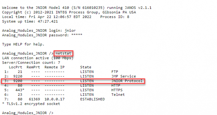
You can check your JNIORs active connections by opening a telnet connection to it. This can be done via command line, or by using the JNIOR’s Web Pages (Java Applets for Series 3 JNIOR). Once you have this connection, you’ll enter the command ‘netstat’. This shows all the active connections on the JNIOR. If the JNIOR device is listening on a port that is defined in the list as the JNIOR protocol, then that is the port number for the JNIOR protocol.
netstat command
Devices that use built-in libraries will usually need to create a JNIOR device inside its interface. When creating the JNIOR device, it will typically auto-populate the device with a username and password (‘jnior’, ‘jnior’), and the port number (usually 9200 which is the default port number for the JNIOR protocol). The information missing that will need to be entered is the IP address of your JNIOR. With the IP address entered, the information required to successfully create a JNIOR device should be done. Commands can then be created using that JNIOR device to be sent to the JNIOR, such as a relay output pulse or macro execution. These commands will be already be created by the built in library and just need to be selected to be used.
If both the Cinema Server and the JNIOR are configured as stated above and the connection doesn’t appear established when trying to send the JNIOR commands, you may need to reboot both devices for your settings to take effect.
MODBUS Protocol
Advantage: It requires little time to setup, needing only the JNIOR to enable the MODBUS application and then the Cinema Server to be configured to connect to the MODBUS protocol.
Disadvantage: Commands are limited to whatever the Cinema Server’s built-in library provides. Available commands vary between Cinema Servers. Connection is only for devices that communicate using a modbus protocol. (GDC is the only Cinema Server that uses the modbus protocol)
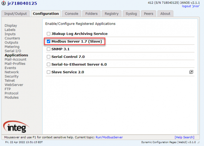
MODBUS is another application on the JNIOR that allows a Cinema Server to connect with the JNIOR. If a Cinema Server doesn’t use the Modbus protocol, it shouldn’t use this type of connection. This application comes pre-installed on the JNIOR, and needs to be enabled to run on boot. To get MODBUS running on your JNIOR you’ll need to enable it by going to the Applications section of the Configuration Tab of the JNIOR Web Pages. You’ll go to the MODBUS application and check the checkbox next to it. Once you’ve done that, you’ll need to reboot the JNIOR to get the application to start running.
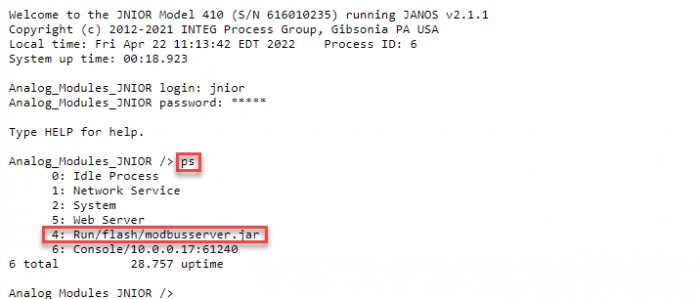
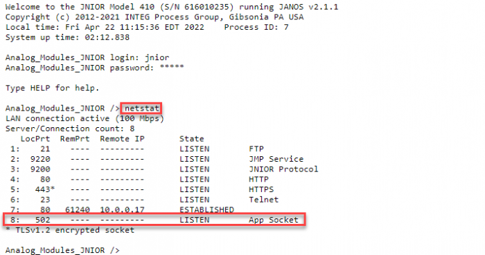
You can check if the application is running after the reboot by going to the Console Tab of the JNIOR Web Pages and entering the command ‘ps’. This will show you all the processes running on the JNIOR, and if you enabled MODBUS is should be listed as one of the those processes. With MODBUS running, you can also check if MODBUS is listening on the correct port by running the ‘netstat’ command. The MODBUS connection should display when the ‘netstat’ command is entered in the command line.
ps commandnetstat command
With MODBUS running, you’ll then need to create a device in the Cinema Server interface to connect to the JNIOR. Communicating with MODBUS will use the Cinema Server’s built-in library. Devices that use built-in libraries will usually need to create a JNIOR device inside its interface. When creating the JNIOR device, it will typically auto-populate the device with a username and password (‘jnior’, ‘jnior’), and the port number (usually 9200 which is the default port number for the JNIOR protocol). The port number will need to be changed to 502 for the modbus protocol. Then the information missing that will still need to be entered is the IP address of your JNIOR. With the IP address entered, the information required to successfully create a JNIOR device should be done. Commands can then be created using that JNIOR device to be sent to the JNIOR, such as a relay output pulse or macro execution. These commands will be already be created by the built in library and just need to be selected to be used.
If both the Cinema Server and the JNIOR are configured as stated above and the connection doesn’t appear established when trying to send the JNIOR commands, you may need to reboot both devices for your settings to take effect.
Cinema Application
Advantage: Execution of macros grants more functionality then what might be available from other connections that can be created.
Disadvantage: Requires more setup compared to other connections that can be made between a Cinema Server and JNIOR.
Another way to connect between a Cinema Server and the JNIOR is the Cinema application. This connection can be done via TCP or Serially. To setup this type of connection we first need to update the JNIOR with the Cinema application. Once Cinema has been installed on your JNIOR, you’ll then need to configure it to connect on a selected port. To do this you need to access the registry of the JNIOR, which can be done via command line or through the JNIOR’s Web Page (Java Applets for Series 3 JNIOR). You’ll need to edit the registry of the Cinema application to properly handle a TCP or Serial connection, which you can read about here. Once the Cinema application’s TCP port/serial settings are entered, the macro and device files will need to be created using the support tool. Macro and device files tell the JNIOR what actions to perform when they receive a specified command sent to the Cinema application. How to create macros can be viewed in a post here.
After you have created macros and published them to your JNIOR, you will need to create a device on the Cinema Server’s interface. Make sure that if you are using a serial connection that you are creating a serial device, or if its an Ethernet connection that its a TCP device. You’ll then enter the same connection settings for that device that you have for the Cinema application on the JNIOR. (For example, if you set the Cinema application to listen on 9600, set the Ethernet device you are creating on the Cinema Server to 9600 as well.)
Example Commands
Finally when that is created, you can then create commands in the Cinema Server to send to the JNIOR. These commands should be made to activate macros on the JNIOR and will use ASCII instead of binary. You can also create Serial Control Commands inside of Cinema. Here are some example commands below:
Macro Commands
run Test\r\n - activates a macro uploaded to the JNIOR called 'Test'
run Macro\r\n - activates a macro uploaded to the JNIOR called 'Macro'
Serial Commands
::C1 - Close relay output 1
::O234 - Open relays 2, 3 and 4
::C* - Close all relay outputs
::O+2 - Open relay 10
::C1p=1000 - Pulse relay 1 closed for 1 second
With this you should be able to send commands from the Cinema Server to the JNIOR using the Cinema Application.
Again, if both the Cinema Server and the JNIOR are configured as stated above and the connection doesn’t appear established when trying to send the JNIOR commands, you may need to reboot both devices for your settings to take effect.
Serial Control
Advantage: It is a lightweight application and won’t use as much processing power as other applications.
Disadvantage: Can only control the JNIORs I/O.
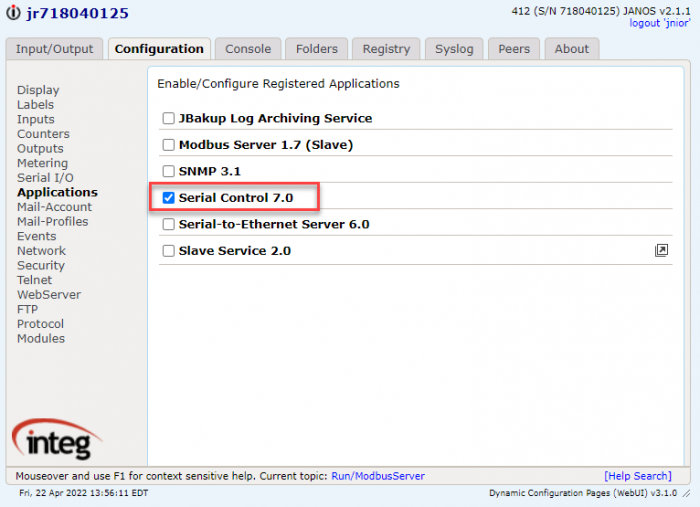
This connection can also be done via TCP or Serially. Every JNIOR comes with bundled software already installed on it, and Serial Control is one of those applications. However, its not set to run so the application doesn’t start when the JNIOR is booted up. To get Serial Control running on your JNIOR you’ll need to enabled it by going to the Applications section of the Configuration Tab of the JNIOR Web Pages. You’ll go to the Serial Control application check the checkbox next to it. Once you’ve done that, you’ll need to reboot the JNIOR to get the application to start running. Once the Serial Control application is running, you will then need to set the port number or serial settings its listening on.
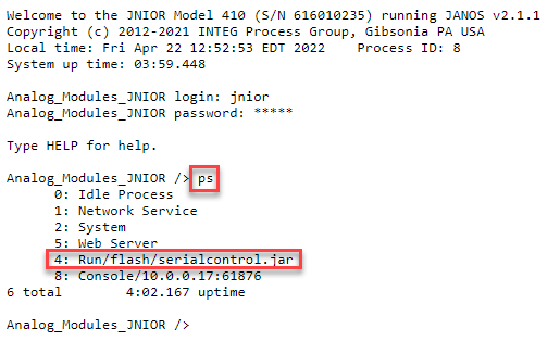
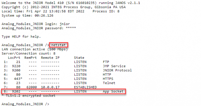
You can check if the application is running after the reboot by going to the Console Tab of the JNIOR Web Pages and entering the command ‘ps’. This will show you all the processes running on the JNIOR, and if you enabled Serial Control is should be listed as one of the those processes. With Serial Control running, you can also check if Serial Control is listening on the correct port by running the ‘netstat’ command. The Serial Control connection should display when the ‘netstat’ command is entered in the command line.
ps commandnetstat command
Once Serial Control is running, now the Cinema Server needs a device created in its interface to connect to the JNIOR. You’ll create an Ethernet or Serial device in the Cinema Server interface, and you’ll set the IP to the IP of the JNIOR. For either a Ethernet connection or serial connection you configure them to match the settings in the Serial Control registry.
Example Commands
Once that device is made, you’ll make commands in the Cinema Server interface to send to the Serial Control application. Here are some examples:
Serial Commands
C1 - Close relay output 1
O234 - Open relays 2, 3 and 4
C* - Close all relay outputs
O+2 - Open relay 10
C1p=1000 - Pulse relay 1 closed for 1 second
Here is also a post that goes over commands that Serial Control can receive after a connection to it is made from the Cinema Server. With these commands created you should be able to send commands from the Cinema Server to Serial Control on the JNIOR.
Like previously, if both the Cinema Server and the JNIOR are configured as stated above and the connection doesn’t appear established when trying to send the JNIOR commands, you may need to reboot both devices for your settings to take effect.
When using the Cinema application to send/receive commands to JNIOR, you may want to better customize the actions your JNIOR can perform past just controlling the JNIOR’s I/O. Creating macros is a great way to get more functionality from sending/receiving commands to the JNIOR. This post will explain how to create and upload macros to your JNIOR.
To create macros you need to have the support tool downloaded, which you can get here.
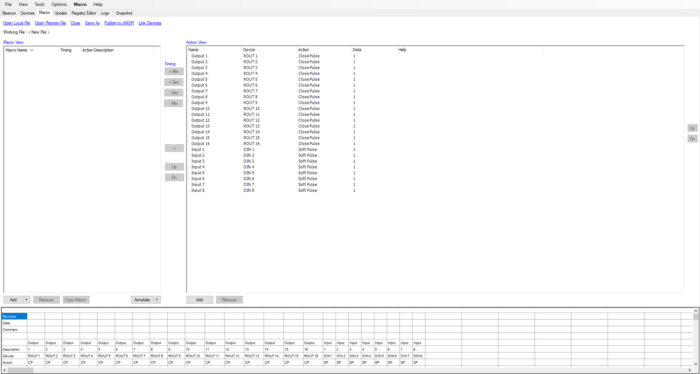
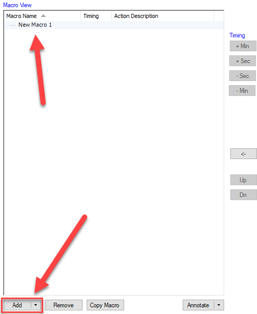
Once the support tool is downloaded, you’ll open it and go to the macro tab. In the macro tab, you can create and upload macros to your JNIOR. To add a new macro, you’ll select the ‘add’ button at the bottom left of the update tab and select ‘macro’. With the new macro added, you can click on the new macro to edit its name.
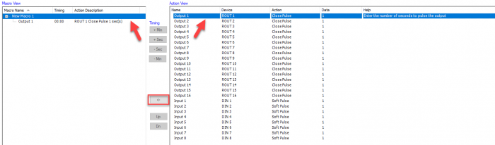
Adding Actions to Macros
After adding and naming the macro, you can then add actions to the macro. The actions are on the right side of the update tab and you can add new actions at the bottom of the action view, or edit existing ones by selecting them and editing the values in their columns. By selecting the macro and then the action you can select the arrow button between them to add the action to the macro.
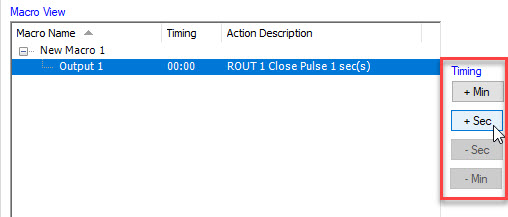
Editing the Macro Cue
Macros can be set to trigger at different times by editing their timing. While an action is selected in a macro, you can press the various timing buttons on the right to add or reduce the time it takes to trigger that action in the macro.
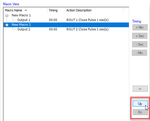
You can also move your macros by shifting them up and down with the Up/Dn buttons. This doesn’t change how the macros execute, but can help you keep your macros in organized.
Once you finish adding your macros and actions, you’ll then need to save and publish your macro file to your JNIOR by selecting the ‘publish to JNIOR’ button. This will prompt you to save your macro file. After you save, you can then select your JNIOR to publish to. With that, you’ll have created and published your macro file to a JNIOR. Now when the JNIOR receives a command to execute a macro you created, it will go through and execute each action inside the macro in order.
Opening an Existing Macro File
Instead of creating a Macro file, you can open one that has already been created and saved. Selecting the Open Local File button will open your file explorer to where Macro files are saved on your PC. Here you can select one you wish to open, and it will populate into the Support Tool Macro tab. You can also select the Open Remote File button, which will open a JNIOR selection screen and allow you to open a Macro file that is loaded on a JNIOR.
Referencing Devices from your Device file in Macros
You may have external devices that you want to control from a JNIOR macro. To do this you first need to create and publish a Device file to the JNIOR. Once that is done, at the top of the Macro tab you’ll want to select the Link Devices button. Your file explorer will open to where your Device files are saved, and you’ll select the one you want to use. With this, you’ll now be able to reference any Device you created in the Device file as a device you can use in the Device column of your actions! If this didn’t work, here is a more detailed walkthrough of this.
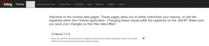
Web Pages have been added for the Cinema application! These web pages have been implemented to make configuring cinema easier. This post will go over the different tabs the Cinema Web Pages have. To start, there are 7 tabs available on the Cinema Web Page. Other then the home page, each tab should display different registry settings to configure for the Cinema application.
Home Tab
The home tab is the opening tab when the cinema web pages are loaded. Unlike the other tabs, this page allows you extra functionality over the cinema application besides editing the registry keys. The first section allows you to enable/disable the cinema application to run on boot. Keep in mind that when changing this setting a reboot is need for it to take effect.
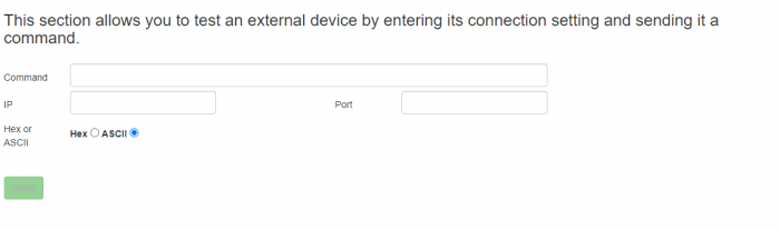
The second section allows you to test the communication settings of an external device. This allows you to test the communication between the JNIOR and an external device before having to create it in the macro and devices files. Below is a quick explanation for each field.
Command – This section is where you enter the command you wish to try sending to the external device.
IP – This is where you enter the IP address of the device you wish to send to.
Port – This is where you enter the Port number of the device you wish to send to.
Hex or ASCII – This sets weather the command you send is in ASCII (text), or hexadecimal format.
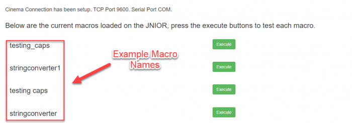
The third section displays the current connection status of the cinema application, and allows you to test macros that have been published to the JNIOR. Clicking execute will run the macros across from it. If Cinema doesn’t have a successful connection setup, it will display what isn’t setup correctly to create a connection to the Cinema application. It will also display if macros haven’t been loaded on the JNIOR yet.
Cinema Server Tab
Cinema.JAR can accept one or more connections from an external device using the Cinema Server Client port and this connection can be over the serial port and/or the Ethernet port. The Cinema Server tab allows you to edit the settings of the Cinema Server Client from the web page. Below is a quick explanation for each field.
TCP Port – Sets the TCP port that the Cinema Server connects on.
Serial Port – Sets the serial connection that the Cinema Server connects on.
Send Unsolicited I/O Alerts – Determines if any Alert such as I/O Counts or Date Stamps should be allowed through the Cinema Server Connection.
Send Ack – Determines if the Cinema Server Connection allows responses to be returned from the external device through the Cinema Server Connection.
Send Counts – Determines if the JNIOR reports each time an input changes to the external device connected through the Cinema Server Connection.
Send Date Stamp – Determines if each report of an I/O change on the JNIOR reported through the Cinema Server Connection gets appended with the current data and time.
Incoming Termination String – Sets the string that Cinema looks for at the end of each message sent to it to know if that is the end of message being sent.
Outgoing Termination String – Sets the string that Cinema adds to the end of each message it sends. The external device being sent to needs to know to look for this Outgoing Termination String.
Enable Serial Commands – Enables commands to be sent in Serial Control Format. This allows commands to be sent through that can close or open outputs on the JNIOR.
Control Panel
The JNIOR Control Panel Switches can be configured to trigger a macro to execute whenever the switch is pressed. The Control Panel tab allows you to assign macros to execute on the 12 control panel switches that are available. This requires you to own the control panel and have it connected to the JNIOR through the JNIOR’s sensor port.
Fire Alarm
The JNIOR can be assigned inputs to activate and release a fire alarm macro. The Fire alarm tab allows you to assign the inputs and the names of the macros that activate when the fire alarm is triggered and released.
Logic and Schedule
Cinema can setup logic statements and time events to determine when macros should be executed. The Logic Tab allows you to run macros based off of the current values of the JNIOR’s I/O as well as when other macros execute. The Schedule Tab allows you to set the time of day, the date, and the reoccurrence of when a macro is executed.
Triggers
Cinema can allow I/O to trigger macros similar to how the control panel works. The Triggers tab lets you assign what macros execute off specific I/O. The I/O in the triggers tab will reflect the type of JNIOR you are configuring.
While JNIOR 412DMX units may be unavailable, JNIOR 410s can be made to work as a substitute. Note that this does NOT work for JNIOR 412s and 414s, as 410s RS-485 compatibility is the reason why it can be used as a 412DMX substitute.
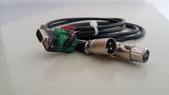
Cabling
When trying to connect to a 410 with DMX, the cabling will need to be corrected as you need to go from an AUX port to a male/female 5-pin XLR connector. By splicing into an existing DMX cable, you can attach a DB9 adapter with screw terminals to the end of the cable. It should look something like the picture below.
Here is the pin numbering for splicing the adapter on. Note the wire colors vary.
        Signal           XLR      DB-9 Male
--------------------  ---------  -----------
Signal Ground (GND)       1          5
Data (D-)                 2          2
Data (D+)                 3          8
Not Used (NC)            4,5     1,3,4,6,7,9
This cable allows the JNIOR to be a DMX FIXTURE. THE RESULTING DMX CONNECTION IS NOT ISOLATED. We recommend using an isolated power supply for the JNIOR and not sharing that voltage with other circuits. Take great care in making ground connections. Note that the JNIOR relay outputs are naturally isolated.
Aux Port Application
Below is an application you’ll need to update and install on the JNIOR. This is required for the JNIOR to interpret DMX communication on the JNIOR.
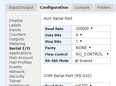
The serial settings of the JNIOR need to be configured so the AUX port output doesn’t disrupt the DMX communications. Below are the settings you need to set for the AUX Port. This is located on the JNIOR\’s Webpage, in the Serial I/O section under the Configuration Tab.
Once the cabling has been created, the DMX Port application is on the JNIOR, and the Serial Settings have been set, DMX communication should be possible on the JNIOR 410.
If you have any questions about this, contact our support to get help with this setup using pure chat or our email: support@integpg.com.
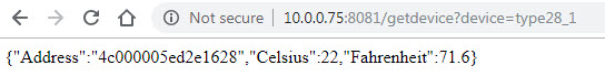
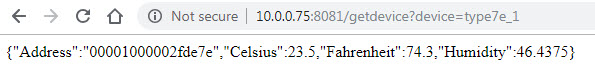
+ Allow you to query the temperature sensor via a HTTP Request. A JSON representation of the device will be returned.
As of now the only available devices are Type28 and Type7E...
Type28 is the temperature probe and Type7E is the environmental sensor.
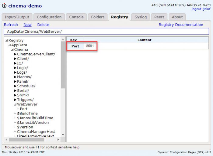
To enable this you will need to set the AppData/Cinema/WebServer/Port registry key. The JNIOR will need to be rebooted after this key has been changed. In this example I chose 8081. Port 80 or 443 is normally the default web server port. This web server port is an additional web server that cinema is hosting to handle these types of requests.
[+] variables that start with $$ are global variables. These are global WITHIN the workspace.
[+] added Control Panel Switch implementation
[+] added a tasks.get WebSocket handler
[+] added a task.list WebSocket handler
[+] added http post functionality
[!] scheduling changes take effect immediately when a workspace is reloaded
[+] validation on task names, device names, logger names, signal names, trigger names, and schedule names to prevent spaces and bad characters. Names can only be alphanumeric and can include underscores.
3.9, 18 nov 2020
[!] fix error where parameters used to have to be named starting with $.
3.8, 07 oct 2020
[!] fix error for only handling 8 output triggers.
[!] fix error where a temp probe couldnt be assigned to a variable.
[+] added http post functionality.
3.7, 02 oct 2020
[+] Added tracking the parent workspace name so that all of the tasks can be removed from the collection that belong to a workspace that is updated or removed.
3.6
[+] Added a tasks.get handler.
[+] Added a tasks.list message.
3.5
[+] Added a user.alert message.
3.4
[+] removed the requirement for the schedule start day.
[+] fixed the schedule reloading so that the new schedule takes effect and does not require a reboot.
It has been a while since Tasker was released. Tasker was a quick attempt at making a replacement for the Task Manager application that has been around for more than a decade, starting on the Series 3.
Ample time has now been taken to create a fully capable application that will be every bit as functional as Task Manager but offer the benefits of a rewrite, using configuration files and the latest web technology.
Some of the changes and new features are as follows:
Faster– The tasks are executed much faster and the triggers and schedule are monitored in real-time instead of once every 5 – 10 seconds.
Workspaces - Separate configuration logic into multiple workspaces. Then multiple workspaces can be loaded on the JNIOR at the same time.
Tasks are now separate from triggers. In Task Manager a Task was created and a Trigger was configured to get the Task to execute. In Tasker 3.0 Tasks are a separate entity that can be executed several different way including manual execution from the configuration page and being requested via an ASCII TCP connection.
Tasks can now send data via an Ethernet connection. To do this, a Device must be created so that the action can specify which device to send the data to. Multiple devices can be configured.
New Actions – We implemented actions that were previously available in Task Manager but are introducing many new actions like external module control, TCP communication and control structures.
Drag n Drop – Drag and Drop functionality makes it easier to design your Task logic.
Signals are now created to assign a specific property of a I/O point or sensor a name. The name can then be used in Tasks, Triggers or Loggers.
Loggers can be created to define the file name and schema or what data should be logged to that file. Each line in a Logger will be prepended with a timestamp followed by a comma. Loggers also allow you to define the number of files that should be kept with the given naming pattern. Name patterns can include date patterns. This will help you create a file per day for example.
Schedule – The schedule has additional options.
JSON Configuration files are used now instead of registry keys. Registry keys were limiting in size. The Series 3 could only store 255 characters in a registry key. It is much easier to upload configuration files to other JNIORs to replicate setups.
User Interface – The User Interface is now a native HTML application that uses the latest web technology. The latest web technology uses native HTML controls and Web-sockets to communicate with the JNIOR from your browser. This will allow accessibility over remote connections as long as port 80 is available. This is now consistent with the communication method used by the DCP. Task Manager had always used Java Applets. The Java Applets have not been able to launch in browsers for several years as they became frowned upon as security vulnerabilities.
This was just a short list of changes and new features. The documentation for Tasker should explain these topics as well as many others. If there is anything you don't understand please reach out to us for help. Additionally, if you have any suggestions or need the JNIOR to do something specific for you, please let us know.
Unlike the Series 4 JNIOR, the Series 3 JNIOR’s do not have a command that can be used to factory reset them. To get a Series 3 JNIOR as close to factory reset is to follow the steps below:
Step 1: Delete the Registry
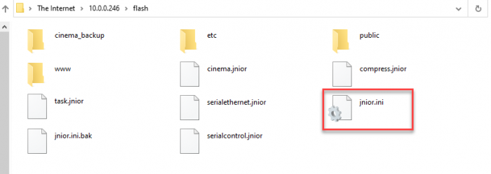
On every JNIOR is a jnior.ini file. This file is the saved registry values on the JNIOR. To reset the registry we will need to remove this file from the JNIOR. Two ways to remove the file is to either right click the JNIOR in the support tool and go to Tools/FTP to access the files on the JNIOR, or make and command line connection and remove the file using the command line. Thing is, the JNIOR automatically backups the registry every couple of minutes, so even though we delete the jnior.ini file, it will repopulate after a few minutes. To make sure the registry does not regenerate, we have to delete the jnior.ini file, and then quickly after pull power from the JNIOR for 30 seconds. This will prevent the a backup of the JNIOR from being created. Below is how to get to the jnior.ini file by using FTP.
Use FTP from support tool and go to the flash folderDelete jnior.ini file and pull power from jnior for 30 seconds
Below is how to remove the jnior.ini with the command line:
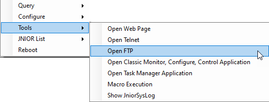
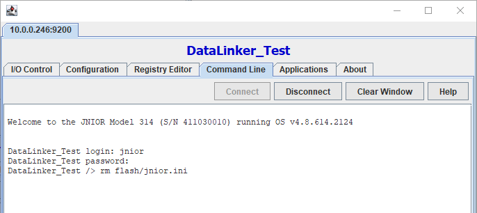
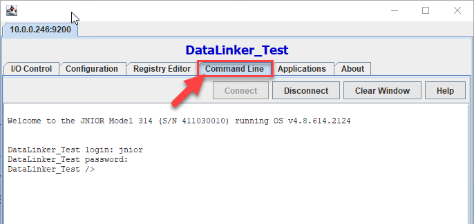
In the picture below we use the Series 3 Java applet configuration page to send command through command line. To open the Java applet, right click the JNIOR in support tool and select Tools/Open Classic Monitor, Configure, Control Application. Then go to the Command Line Tab and that’s where you’ll enter the command rm flash/jnior.ini. This removes the jnior.ini file in the flash folder from the JNIOR.
Go to the Command Line tab once you login using jnior, jniorEnter the command rm flash/jnior.ini and hit enter, then remove power for 30 seconds
Step 2: jrflash -f
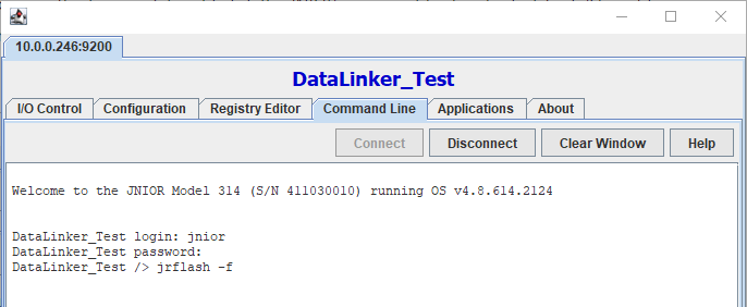
After resetting the registry, we’ll then want to reformat the flash memory. To do this, if you haven’t already we’ll need to make a command line connection to the JNIOR. Once a command line connection is made, you’ll enter the command jrflash -f. Let this command run, and once this is done you’ll re-update the JNIOR with the Series 3 All-In-One update project. In the picture below we use the Series 3 Java applet configuration page to send command through command line. To open the Java applet, right click the JNIOR in support tool and select Tools/Open Classic Monitor, Configure, Control Application. Then go to the Command Line Tab and that’s where you’ll enter the command.
Go to the Command Line tab once you login using jnior, jnior Enter the command jrflash -f and hit enter, when command finishes update JNIOR using Series 3 All-in-one update project
Step 3: reboot -a
Once the flash has been reformatted and the JNIOR’s been reupdated with the Series 3 All-in-one update project, you’ll connect to the command line again the same way you did for the last step and enter one more command. Enter reboot -a, as this will reset the heap memory. This clears up fragmented memory, so when memory is being allocated for applications or files to be moved on the JNIOR, enough space is available for them to exist.
After that, your Series 3 JNIOR should be as close to factory reset as possible!