A controller depends on the availability of good clean and stable power. Unfortunately with the JNIOR any small interruption or glitch in the power source results in a reboot. Applications need to be written to handle unscheduled restarts.

The recommended solution is to place all critical systems on an Uninterruptible Power Source (UPS) like those available from APC.

Things like air conditioner compressors can cause momentary dips in local power. The amperage of the power circuit and distance from the subpanel come into play here. The voltage available at the end of wiring that operates near its rated current or that may be lengthy tends to be easily affected by current surges. The voltage drops very briefly. That minor drop can be significant enough to reboot a JNIOR located on that circuit. And, the addition of a separate UPS means extra cost.

The 412DMX model of JNIOR is being developed and here we are testing the new internal power circuit. This JNIOR will incorporate “ride-thru” power supply technology. Regardless of the selection of buzz words that we use to describe it, the basic function is to store enough energy to keep the JNIOR powered through a momentary loss of external power. The implementation will flash the blue power LED to indicate the loss of external power. If power is restored before the stored energy runs out then the JNIOR continues unaffected. The loss of external power and its restoration are logged in the system log. Here we let it run out to see how long we really have.

Can you do that? Does it work? Well observe the first prototype:

The birth of any operating system, and this is true for JANOS (Series 4) as well, begins with serial access to a command line interface. There are often boot and diagnostic messages transmitted over that first communications channel. The Series 3 is based up the TINI Operating System and the RS-232 (COM) port located at the bottom of the unit next to the ETHERNET (LAN) port is that very diagnostic channel for TINI.

The DB-9F connector there was designed to be directly connected to the COM serial port on the PC. Only a straight-thru M-F serial cable was required. Communications are at 115.2 Kbaud, 8 data bits, 1 stop bit and no parity. There is no handshake and this port is 3-wire (Rx, Tx and GND). Today no PC is manufactured with such a COM port. Fortunately USB-to-Serial adapters are readily available and provide the necessary compatible connection point.

If you are working with the JNIOR for the first time you may want to first try this serial connection. A new unit or one that has been configured to work elsewhere will not be immediately compatible with your network. While there are alternative solutions to the network setup the serial connection is the most basic. It is the only place where you can “watch” the unit go through it’s boot procedures.

This connection point and its use remain consistent through the Series 4 products. The command line interface found there is the same. There is a huge difference in response (where the Series 4 shines) and the diagnostic messages are different.

Now with the JNIOR powered and the serial port connected to the PC you can use a Terminal program. We used to use hypertext but now MS no longer distributes that. Nice of them, eh? You can use PuTTY (http://www.putty.org/) and configure for the proper baud rate (115,200) and data format (8/1/none).

If you open the port and strike any key (i.e. Enter) you should obtain something like the following on a Series 3).

Here, for example, is a terminal program that I designed for JNIOR use in-house but PuTTY works perfectly. This one has the capability to force a jnior:jnior login (administrator account ‘jnior’, default password ‘jnior’) because, as you can imagine, we here at INTEG log into JNIORs a lot!

If you have obtained your JNIOR from a prior installation the passwords may have been changed. There is a significant chance though that they have not and the above jnior:jnior login could work. Most Series 3 JNIORs have gone into physically secure networks where customers have not had the need to vary from default passwords.

If you can successfully login to the ‘jnior’ account you will reach the command line. Note that if you access the command line through a network Telnet connection the ‘TINI’ prompt is replaced by the unit’s defined hostname. Byte default the hostname is the unit’s serial number prefixed with ‘jr’.

There are a number of commands available at this point. The command line here emulates some DOS commands and some Linux commands. the goal being that it should appear familiar to those that work in either environment. But there are differences and the HELP command can be used to retrieve some limited assistance.

If the ‘jnior’ account password has been changed there is another administrator’s account that you can try. Try to login to the ‘admin’ account using the default password ‘admin’.

The Series 3 does not have a USERS command that would list the set of defined users. This has been added in the Series 4. Most customers are unaware of the ‘jnior’ account out of necessity but are not aware that there are also ‘guest’, ‘user’ and ‘admin’ accounts the latter also being an administrator.

On the Series 3 you can check the available accounts by displaying the content of the etc/passwd file. There is an entry in this file for each user. The username is apparent although the password is encrypted. The trailing user ID represents the user level. A ‘128’ signifies an administrator. A ’64’ a user who does not have administrator privileges but can control the unit’s outputs. And the ‘0’ representing a guest who can monitor the JNIOR’s IO status but cannot alter anything.

It is highly likely that the prior administrator of your JNIOR was unaware of these accounts and you can gain access using the ‘admin’ account. You can then utilize the PASSWD command to reset the password for the ‘jnior’ account. Um, perhaps setting it back to the default until you place your Series 3 JNIOR in service on-line someplace.

Note that you can use the ‘rm etc/passwd’ command and delete the passwd file and reboot (use the ‘reboot’ command or pull power). The boot process will restore the default etc/passwd file and therefore all of the default accounts.

If you cannot gain access with either the ‘jnior’ or ‘admin’ accounts then a more elaborate procedure will be required. That is beyond the scope of this thread. I’ll address it in another.

So now you are connected to the serial COM port (labelled “RS-232”) and it is supposedly the “diagnostic port”. That would tend to mean that the system might just blurt diagnostic messages out of this port regardless of what you might otherwise be using it for. Well that is true. Generally these messages are only issued during boot up. And, you can disable them if you are planning on using the port to communicate with another device.

So let’s watch the boot. The Series 3 is painful in that the boot takes a minute. That is very much unlike the Series 4 which completes the boot process so fast that you have barely removed your hand from the power connector. Here’s the Series 3 boot:

By the way the POR (Power On Reset) count reported in the above video is 00000001 because the battery in that unit is DEAD. This is likely going to be the case in many Series 3 units now that the line is over a decade old. If you are handy with the soldering iron that can be fixed. See the post 310/312/314 Battery Replacement.

Under certain conditions the Series 3 JNIORs are not able to obtain IP addressing via DHCP. This is due to a flaw in the early implementation of IPv6, The bug is part of the built-in TINI operating system supplied by the component manufacturer and INTEG is not able to directly correct it.

You can disable the use of IPv6 by making the call to com.dalsemi.tininet.TININet.enableIPv6 with a ‘false’ boolean parameter. As this would require a change to the OS release and the product being no longer in production and deprecated, the recommendation is to disable IPv6 on the local subnet or use a fixed IP address. Since a fixed IP address is usually required and few JNIORs actually use DHCP the OS update is not scheduled.

Alternatively an application can be set to run on boot that makes the call.

If you have a 310/312/314 Series 3 JNIOR you may also have its wall power supply. As we ship JNIORs in bulk we often supply them without the corresponding power supplies. Customers often use their own power sources. So you might just have the JNIOR or perhaps its original supply is still in service with a replacement Series 4.

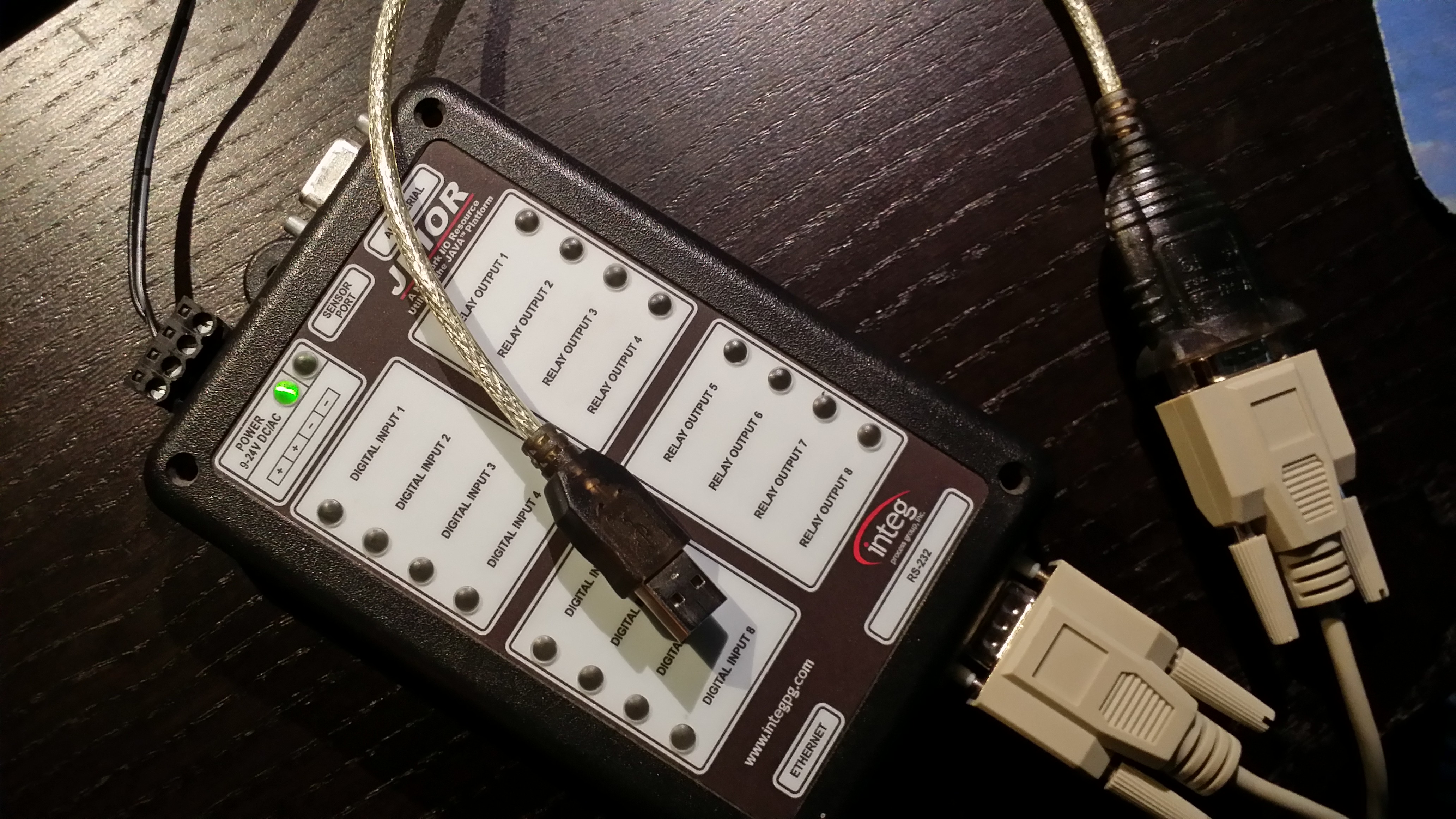
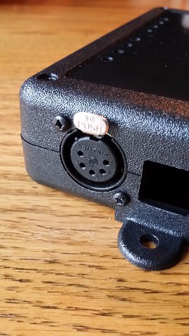
By itself the JNIOR is not self explanatory. It’s a 6″ by 4″ by a little over 1″ black box with connectors filling the 4 sides. On the cover there are places for 18 LED indicators. You may recognize two DB-9F connectors for serial communications. You likely notice the CAT5 LAN connector. But the rest is somewhat mysterious. So what is next?

Typically we supply the JNIOR with a 12VDC Regulated 1A wall mounted power supply. Some series 3 are labelled with ‘9-24V DC/AC’ and some with ’12-24V DC/AC’. While the JNIOR will operate with a 9VDC supply that turns out to be too close to the low side and does not afford enough margin to insure reliable operation under all conditions. So at some point we made 12V the recommended low end.

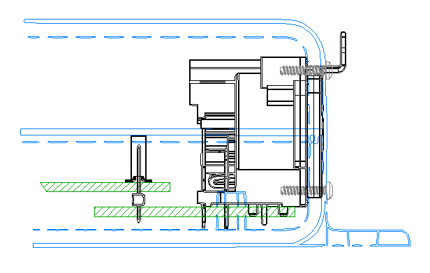
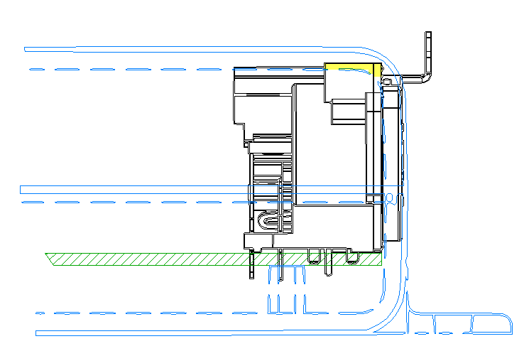
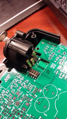
The 4-position connector at the top of the unit is for the supply. The positive lead is connected to either of the left two positions (1 or 2) and the negative to either of the right two (3 or 4). We supply connectors wired to the center two positions, positive to pin 2 and negative to pin 3. The other two pins are there to allow you to tap this voltage for use in simple circuits involving the digital inputs or relay outputs as needed. Of course if an AC power source is used it is connected to pins 2 and 3 without regards to polarity.

One advantage to this particular design is that if you make an error and connect the DC supply backwards it will still work. Note though that the negative lead IS NOT circuit GND. More on that later.

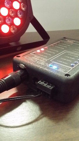
Using any appropriate power source (and we all have a box of them laying around these days) the JNIOR should power up. A GREEN LED to the left next to the power specification will illuminate to indicate that power has been applied. We improved on this in the Series 4. The leftmost LED on the Series 4 is BLUE. That greatly enhances the product. :-)

Actually, it is hard to resist a BLUE LED. They were a rarity for many years. When we built the first Series 4 units the prototype boards were installed in Series 3 enclosures. I elected to use a BLUE LED for the power indicator so we could easily tell a prototype Series 4 from a standard Series 3. We have so many mounted around the office. It was supposed to be temporary but democracy prevailed and we were destined to leave it that way.

So power up your Series 3. If the LED illuminates then your internal power rails have reached their proper voltages. You should also see the rightmost LED (ORANGE) come on for a brief period. That is illuminated during the OS boot. It also flashes indicating connection status. More on that at some other time. The rest of the indicators are RED and will display the state of the corresponding input or output.

By the way if you have a Series 4 you will notice one other difference (besides the BLUE LED). When the Series 4 boots the ORANGE Status LED flashes on for no more than a second or two. That is because JANOS boots in just a couple of seconds and applications start in seconds.

The operating system on the Series 3 however can take minutes to boot. The ORANGE status LED only illuminating as the base TINI operating system loads and subsequently the JniorOS loads. Once that is done applications then load. The boot process is lengthy but the unit will get it job done.

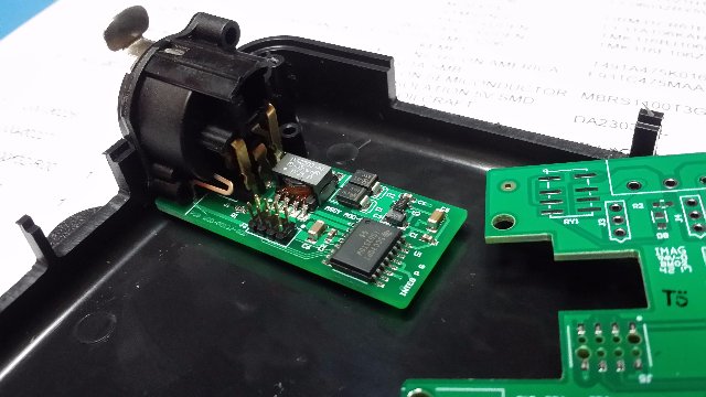
So the Series 3 internal power supply is a bit unconventional. While we typically power the unit with 12VDC it is designed to be powered by an AC source. Here is the front end. I had to go back and reinstall OrCAD to get to these schematics. We use Altium for the Series 4.

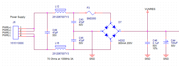
It is important here to note that the negative (-) power supply connection IS NOT the same as GND.

Now that generally isn’t an issue as all of the JNIOR’s inputs are isolated and all of the outputs are dry relay contacts and therefore also isolated. The GND signal does appear on the serial connectors and on the Sensor Port. The external modules that are designed to run on our Sensor Port are also isolated. The bottom line is that you can possibly cause an issue if you ground (GND) the negative (-) supply lead and then also connect the GND pin of either serial port. This is also true with the Series 4 with the exception of the 412DMX that is currently under development.

Another issue that has been corrected in the Series 4 JNIOR is that the negative path is not fused. In this case if a grounding problem occurs and you use the GND pin of one of the serial ports you can cause high current to flow through the product. As mentioned this has been corrected with the addition of the second fuse on Series 4 units.

The VUNREG here supplies the rest of the power supply regulation. With a 12VDC regulated source VUNREG will be somewhat less than 12V but sufficient to power the regulator that generates the internal 5V rail. That was not true with a 9VDC source under some load. Thus, the change to a minimum 12VDC.

Another concern here is that if you use a 24VRMS AC source VUNREG becomes 34V challenging the 5V regulator to follow. This is easily worsened in an HVAC environment where the 24VAC supply can be an unloaded transformer with more like 30V+ RMS. VUNREG can exceed 40V and component ratings including the rating of the subsequent 5V regulator become a concern.

So run the JNIOR with a 12VDC 1A regulated supply and avoid issues. Use increased voltages with caution.

One does not need to use a Regulated external supply. That does insure though that you have precisely the voltage that you want. Unregulated supplies tend to vary more significantly in voltage than you would think from the nominal.

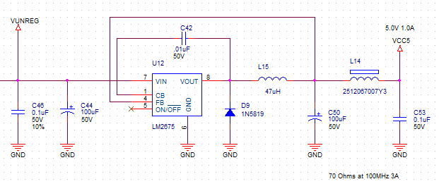
The internal 5V (VCC5) is used to power our relay coils. It if stepped down further to provide the 3.3V (VCC) and 1.8V (VCC1) rails that the processor and digital circuits require.

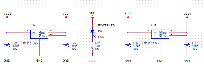
You can see here that the GREEN (BLUE in Series 4) Power LED illuminates when the 3.3V rail is powered.

The internal Series 3 power supply produces 5V at 0.75A (stepped up to 1A with Series 4) driving the rest of the product. In addition to relay coils the 5V is presented to the Sensor Port circuit as a source of power for external modules. The Series 3 also supplies the VUNREG to the Sensor Port which was not used and removed for Series 4.

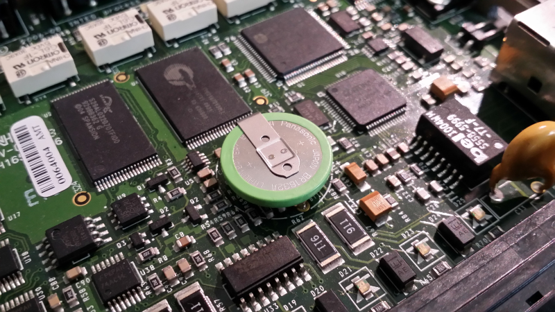
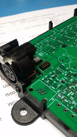
To verify the supplies on the bench, power the JNIOR with 12VDC. You can check each rail across the associated capacitors as show below.

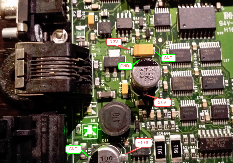
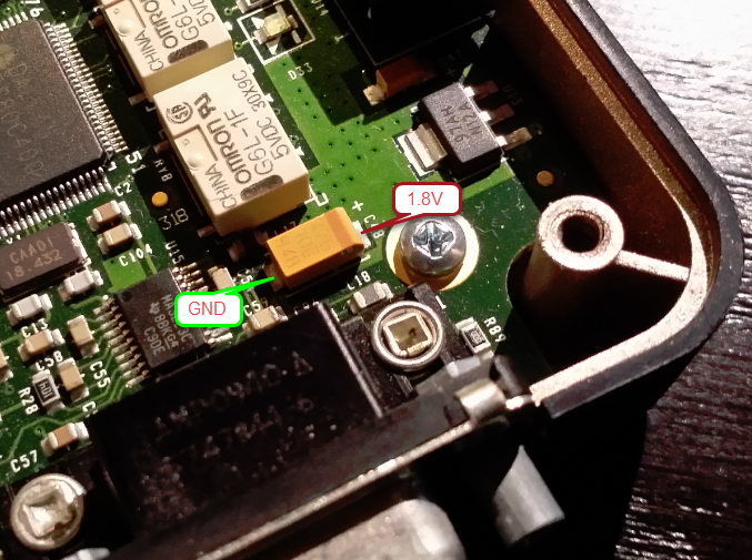
Here we note that VUNREG is approximately 10.6V showing the diode drops from the supplied 12V inherent in the full-wave bridge. The 5V (VCC5) and 3.3V (VCC) rails are nearby and easily checked. The 1.8V (VCC1) rail is developed at the far other end of the board as shown below.

That pretty much covers the power supply requirements, powering your JNIOR and testing voltages.

If you have a Series 3 that no longer functions, check carefully for evidence of damage from over-voltage or high-current in the area of the 5V regulator. The use of excessive input voltages can melt traces around the power connector. A grounding issue can cause damage to the 5V regulator U12 which can show physical damage. In these cases the JNIOR more than likely cannot be repaired.

In some cases the Power LED did not illuminate as a result of a bad LED or poor soldering. Voltages are otherwise as expected. Most of those failures are caught in production. A marginal solder joint can operate for some time but as pass production tests. But after aging it can present as an open circuit.

This power supply has proven to be very reliable. INTEG has seen an extremely small percentage in failure rate. In general, most causes have been tracked to improper external wiring and severe grounding issues.

The Series 3 JNIOR is no longer in production. The 310, 312 and 314 have some time ago been replaced by the much more capable Series 4 models 410, 412 and 414. All versions of JNIOR utilize a 3V Lithium cell as battery backup for the time clock and the RAM based portion of the file system. While the Series 4 employ standard coin cells (CR2016 or CR2032) that can be easily replaced with batteries available from your local convenience store, the Series 3 batteries are soldered in place.

JNIOR Series 3 Coin Battery

The one shown here is dead. So DEAD in fact that you can barely detect the 0.008 volts that remain.

These batteries were expected to last 10 years in the typical JNIOR application where the unit remains powered 24/7 or nearly so. In applications where the JNIOR is powered less than 8 hours per day these batteries need to be replaced after about 6 years of service.

Note that the battery IS NOT required for product operation. In situations where the time clock needs to be accurate (scheduling) then units should be updating their clocks from a separate time server (NTP) through the network. The clock will be set after booting. The RAM based portion of the file system retains log files which are normally only necessary for debugging. Those files need not be retained through power loss.

INTEG no longer has inventory for these batteries. It is not cost effective for us to replace them.

If you feel confident using a soldering iron, these batteries can be replaced.

The original battery was Panasonic BR1632A/HAN and is currently not in stock at DigiKey. However, you can use the Panasonic BR-1632/HFN battery and at this writing there appears to be sufficient stock. These are less than $2 in quantities of a few.
https://www.digikey.com/products/en?keywords=P299-ND

You can however use any 3V battery source. You might add wires to accept wired batteries. You might even find a coin cell holder to fit. The pin spacing is 15.2mm. But since you will likely not need to replace the battery or another half dozen years you might not get too fancy.

Desoldering is tricky. First of all the solder has a high melting temperature due to its RoHS nature. Secondly the (-) GND terminal connects to the ground plane which represents a fair heat sink. It will take time and a lot of heat to loosen the negative battery terminal. Replacement is simpler if you first carefully cut the existing battery off of the board. The positive lead can be removed easily with the simplest desoldering equipment. The negative lead will take some effort. I end up using a hot air soldering iron in combination with a desoldering station. Be patient. It can be done.

Even though an old battery may be dead it should be disposed of properly. Most instructions for Lithium cell displosal are referring to serious batteries like that for your laptop computer. Those may require a more complicated procedure. If necessary in this case you can simply wrap the battery with tape sufficient to prevent the accidental shorting of the contacts and toss it out with your trash.

There is one additional note of caution. You will note that there are surface mount components under the battery itself and near the terminals. Care must be taken to not disturb those components. Don’t damage them if you go to cut the battery off of the board. Watch that you don’t apply so much heat to the terminals that you loosen the surface mount components. Apply heat only to the rear of the board.

If you damage those circuits you will impact product operation.

As you know we have been supporting ZIP and JAR files (they are the same as far as JANOS is concerned) for a while. JAR files being predominantly for application programs and Java support. More recent OS versions allow the WebServer to serve files directly out of a ZIP library. The DCP is an example where you need only add the www.zip file to the /flash folder to install the set of files that are the DCP. There is no need to expand the library.

To do this JANOS is able to understand the ZIP/JAR file structure and extract data stored within it with either the STORE or DEFLATE methods. Presently JANOS cannot handle the LZW compression or many other ZIP options such as encryption.

I had once developed a program called “Curator” which was a backup utility that worked much like SVN and stored all of its data using LZW compression. We were always amazed at the compression ratios. I had even worried at times that there might have been a problem in figuring that ratio because sometimes it seemed way off. But the program worked and accurately recovered data.

So I do have code that I have written (although in C++ in that case) that can be used in JANOS to handle LZW. We just haven’t encountered it. Apparently DEFLATE is the compression method of choice.

So I expect that we will encounter externally zipped libraries that JANOS will not be able to process. In those cases depending on the reasons for the incompatibility I am prepared to implement the fix.

But the question now is whether or not there would be any use in the JAR command being able to compress files and create libraries? I realize it has been suggested and even entered in our Redmine system. Would this be something worth doing?

Would you trust your controller directly connected to the Internet?

We’ve been testing a JNIOR 410 on the network with only the following safeguards:

  1. Disable all accounts except the administrator ‘jnior’ account.
  2. Changed the ‘jnior’ account password.

There has been enough malicious activity attempting to login into the Telnet port that we have an application processing the access/log failed login reports and mapping the host locations. Try http://honeypot.integpg.com or https://honeypot.integpg.com if you prefer a secure connection.

Note that this unit is running the current Release Candidate for JANOS v1.6.2 as we have continued to enhance the unit’s ability to withstand life on the open network.

By the way there are a couple of publicly accessible web pages on this unit:

http://honeypot.integpg.com/RegistryDoc.html
http://honeypot.integpg.com/map.php

The Series 3 JNIOR continues to be a reliable workhorse in a number of industries. The Series 3 models (310, 312, and 314) however no longer represent the performance, reliability and stability of the current JNIOR controller line. We no longer produce them. While you would likely benefit from an upgrade to a Series 4 model (410, 412, or 414), doing so is still your decision. The change is almost seamless. Just know that INTEG will dedicate itself to the success of your conversion with the same attention and personal support that you have always experienced.

Just a few added benefits of the Series 4:

  • Secure network connection using HTTPS, STARTTLS, etc.
  • Faster execution making applications more responsive.
  • Boots in only a few seconds.
  • Dynamic Configuration Pages (DCP) replaces the Java Applet panel.
  • Emphasis on Security.
  • Simpler approach to application programming makes user programming even more feasible.
  • Enhanced WebServer provides for the development of state of the art Web interfaces.
  • Supports server-side scripting (PHP).
  • Provides Websockets alternative to the binary JNIOR Protocol.
  • And much more…

The JNIOR can create a network capture! This network capture can be loaded in a sniffer application such as Wireshark for protocol analysis. To do this simply follow a few steps.

  1. Create a telnet connection to the unit. DO NOT USE THE DCP AS THIS CREATES A LOT OF EXTRA TRAFFIC THAT WILL FILL UP THE BUFFER.
  2. Execute the netstat -r command. This step is optional. If you are going to conduct a test procedure then you might want to execute this command so that only the traffic that occurs during your test will be captured.
  3. Conduct your test
  4. Use the telnet connection to execute the netstat -c command. This will create the capture file with the network buffer content.
  5. Use the DCP and the folders tab to pull the resulting network.ngpcap file. It is in the temp directory. It will be removed when the unit reboots!

You may not know that we are creating a JNIOR Model 412 that supports the DMX512 protocol for lighting control. Basically a DMX Output port replaces the AUX serial port that we find normally on the JNIOR. This will be dubbed the JNIOR 412DMX.

An initial prototype was completed and tested. It is functional. However, an issue in the mechanical mounting of the required 5-pin XLR connector necessitated a revision. By the slightest amount the connector interfered with the enclosure cover when mounted on the main PCB. While some creative machining could accommodate the connector it is not the proper way to do it. So the revision lowers the connector in an arrange as shown here. This should do just fine. We will see in a week or so.

This also avoids an issue that Kevin pointed out where the release tab was sitting higher than the unit. It could easily be damaged or damage something else. Here we see that it will be safely below the top of the cover.

In case you couldn’t picture the issue I show it here with the interference highlighted in yellow. You can also see how the release tab is inconveniently placed.

The solution adds a little cost but is the proper implementation.

I’ve located the entire DMX512 ISOLATED circuit on that little piece of PCB so this could be used by other product models.

The PCBs will be in this week and I’ll have to build a set. I milled one housing this morning and mounted the XLR connector to see how it likes its new home.

Now let’s hope that the PCB arrangement lines the connector up for this.

Yeah so the R01 boards are in. The revision was needed to move that XLR connector down. Perhaps you are mechanically inclined and can imagine what is involved in placing the DMX connector on the side of the enclosure. You need to reference the dimensions through the plastic housing and up through the PCB mounts and then onto the daughter board. So even though it can be done you are never 100% certain that you have it right until.. the hardware shows up.

So there is joy! Time to celebrate with some whiskey, right?

This is an ISOLATED DMX512 Output port. The isolation transformer is a tall component and that’s what that square recess is for. It will sit there. All of the RS-485 hardware and isolation is on that small PCB. The connector just carries Rx, Tx, Gnd, 3.3V and CHASIS connections. And that board will let me put these XLR connectors side-by-side for a product that has multiple outputs.

Well I’ve populated the DMX module. Everything looks good except I need to used a slightly taller pin header. Not a problem.

The 412DMX is ready to go. I just need to pull the package together for production.

This prototype has 20 seconds of ride-thru power backup and 128MB of Flash storage. The 5-pin standard DMX XLR connector sits perfectly now in place of the usual AUX port.

Did you know that I have been tweeting my progress with the 412DMX (hastag #412DMX) on Twitter? Follow us @integpg.

I’ve been machining the first enclosure for this. There’s a video of some of it on YouTube.

The USERADD command is used to add a new user to the system. There can be as many as 32 users. A unique user name no longer than 9 characters must be specified.

bruce_dev /> useradd
USERADD user

Options:
 -A             Administrator rights
 -C             Control rights
 -D             Disabled account

Adds a user to the system.

bruce_dev />

The new account can be tagged as Administrator, Control, or Disabled using the appropriate options. These account tags are described in detail in the USERS command topic.

The following command creates the ‘tech’ account which will be tagged with Control permissions. It will initially be Disabled.

bruce_dev /> useradd -cd tech
Enter password: *****
Reenter password: *****
tech added with UID 3
bruce_dev />

Note that an initial password is requested. The password can later be changed using the PASSWD command.

bruce_dev /> users
 guest       0  
 jnior       1  Administrator
 tech        3  Control, Disabled
 user        2  Control

bruce_dev />