Signals Tab⚓︎
The Signals tab allows you to create a reference for values from the JNIOR such as the I/O and expansion module values. Signals are useful as they can be referenced like syntax values.
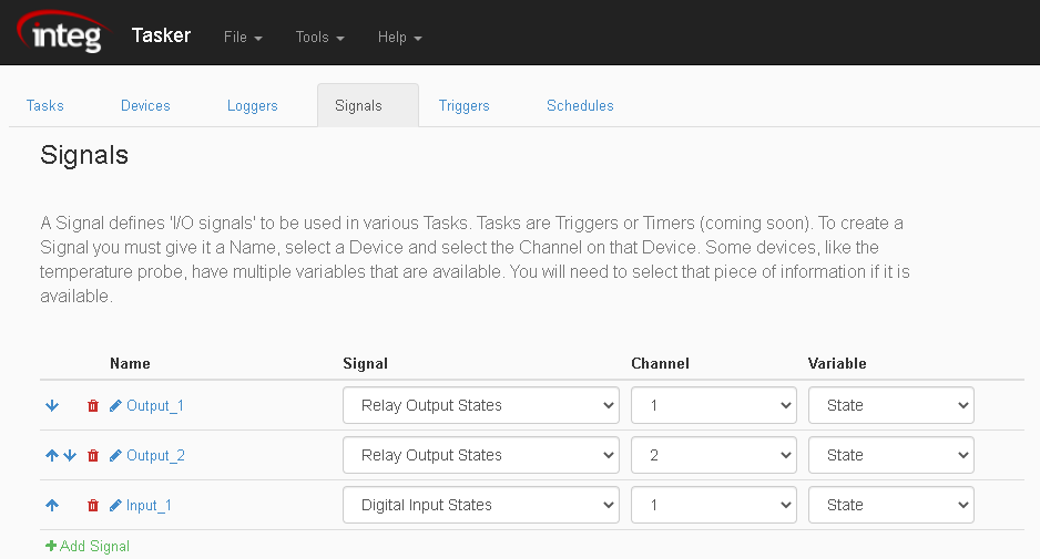
Below are the different options when using the Signals Tab:
- Adding a Signal - The 'Add Signal' option adds a signal to the Signal Tab. The added signal can then be referenced from other tabs.

- Removing a Signal - Use the trash icon to delete a signal. This will remove the signal from the list of signals.

- Reordering a Signal - When two or more tasks are added in the Tasks Tab, arrows next to each task will appear. These arrows shift signals up and down within the list of signals, allowing you to reorder them.

- Renaming a Signal - Use the pencil icon to rename a signal.

Signal Types⚓︎
There are different types of signals pertaining to the JNIOR I/O and its expansion modules. NOTE: options that are grayed out and in italics are not implemented yet...
-
Digital Inputs - Digital Input signals represent the internal inputs on the JNIOR. The max channel number that can be monitored in Tasker is 16. The values that can be monitored of inputs is there states (if they are on or off).
-
Relay Outputs - Relay Output signals represent the internal outputs on the JNIOR. The max channel number that can be monitored in Tasker is 16. The values that can be monitored of inputs is there states (if they are on or off).
-
Temperature Probe - Temperature Probe signals represent values from the Temperature Probe. The max channel number that can be monitored is 2, as only two Temperature Probes can be connected at the same time. The values that can be monitored from the Probe is the degrees its reading in Celsius or Farhenheit.
-
Environmental Sensor - Environmental Sensor signals represent values from the Environmental Sensor. The max channel number that can be monitored is 2, as only two Environmental Sensor can be connected at the same time. The values that can be monitored from the Sensor are Celsius, Farhenheit or Humidity.
-
4-20ma Inputs - 4-20ma Input signals represent the inputs on the 4-20ma expansion module. The max channel number that can be monitored is 8, since each module has 4 inputs and you can have 2 connected max. The values that can be monitored from the 4-20ma inputs is the raw value, which monitors the input in units, and the scaled value which monitors the inputs in MA from 4 to 20.
-
4-20ma Outputs - 4-20ma Output signals represent the outputs on the 4-20ma expansion module. The max channel number that can be monitored is 4, since each module has 2 outputs and you can have 2 connected max. The values that can be monitored from the 4-20ma outputs is the raw value, which monitors the input in units, and the scaled value which monitors the inputs in MA from 4 to 20.
-
10volt Inputs - 10volt Input signals represent the inputs on the 10volt expansion module. The max channel number that can be monitored is 8, since each module has 4 inputs and you can have 2 connected max. The values that can be monitored from the 10volt inputs is the raw value, which monitors the input in units, and the scaled value which monitors the inputs in Volts from 0 to 10.
-
10volt Outputs - 10volt output signals represent the outputs on the 10volt expansion module. The max channel number that can be monitored is 4, since each module has 2 outputs and you can have 2 connected max. The values that can be monitored from the 10volt outputs is the raw value, which monitors the output in units, and the scaled value which monitors the inputs in Volts from 0 to 10.