Iolog Command⚓︎
We are all familiar with logs. These are text files someplace that list events such as logins, configuration changes, errors, etc. On the JNIOR the jniorsys.log file is one such log. These things are useful for systems and web servers. The JNIOR is also a controller and it can be very useful to have a log of I/O activity either digital or serial. This is provided by the IOLOG command.
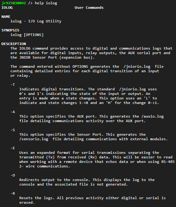
The above HELP alludes to some different logging capabilities. There is something with transitions. That is a detailed log of recent Digital Input and Relay Output transitions. That even includes relays contained in the external expansion modules. The AUX port supports a bidirectional Transmission Log that details communications traffic that includes both the bytes and the timing. There is also a log for the Sensor Port.
The Series 4 JNIOR by default logs all all of this activity to internal buffers. At any time you can dump the log buffers into a file or to the display using the IOLOG command. The IOLOG -R command can be used to reset a log. This can be useful in debugging where you don’t want to be distracted by prior data. I will show some examples.
Let’s start with the AUX Serial Port since it is fresh in my mind. Here the IOLOG -AR command will remove historical data from the AUX port transmission log. The does not affect the other logs. The IOLOG -AO comand will display the log content. For example…
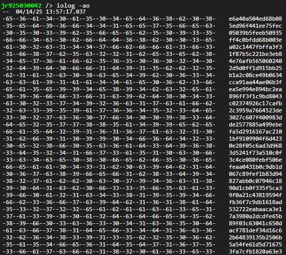
Here we see data in a traditional dump format with 16 bytes displayed in hexadecimal on the left and an ASCII representation of each byte on the right. If the byte does not represent a printable ASCII character it is replaced with a period ‘.’ in the text display.
The AUX serial communications can be bidirectional. Bytes received by the JNIOR are shown enclosed by a dash ‘-‘. In the example above there are single characters received (keypress codes). When a longer message is received the dashes make the incoming data appear to be desplayed over a background line. It is just a way to distinguish direction.
If the channel remains quiet for a couple of seconds, the IOLOG output includes a timestamp and includes the duration of the pause. All of this can be very helpful in debugging a serial communications based application.
The data displayed here is actual results from an HMI test. The content is explained in detail in a different thread. Here is the link to that discussion viewtopic.php?f=5&t=158&start=20#p316. The interface program generating these communications was developed in the thread.
The AUX Transmission log can be sent to a file using the IOLOG -A command.

The file will then contain the data in the same format displayed in the prior post.
The Digital I/O log has quite a different appearance. This is generated using the IOLOG -O command. The digital log is the default log assumed by the command.
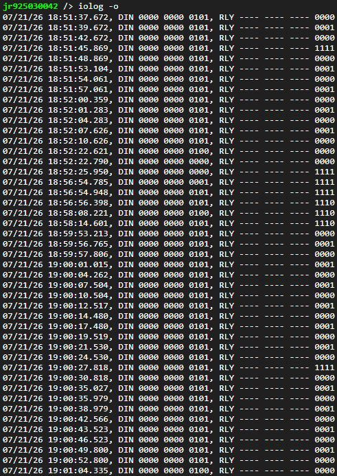
This log is generated by combining separate input and output logs. Each can contain up to 500 transitions. Depending on how frequently inputs and relays change you could have data spanning weeks or simply minutes.
Each line represents at least one transition. There is a timestamp to the millisecond. A ‘1’ indicates when an input (DIN) is activated or a Relay (RLY) closed. The inputs and relays are shown from right to left. So the last transition in the above log shows Relay Output 2 opening. There can be up to 16 relays and 12 inputs logged.
The IOLOG -R command will reset the digital log and not affect others. The IOLOG command without options will store the digital log in a file.
There is also a log for the Sensor Port but unless you are intimately familiar with Dallas 1-Wire communications none of it will make sense. You can write an application to take control over the Sensor Port and communicate with a custom device or non-standard device. It you are working at that level then this log could be very helpful. The Sensor Port log follows the same format as the AUX Transmission Log.