JNIOR Overview⚓︎
Models⚓︎
JNIOR, a Network I/O Resource utilizing the JAVA™ platform, is a cost-effective automation controller that communicates over a network using TCP/IP via an Ethernet Port or its serial port. The JNIOR is a general-purpose automation controller and I/O device that is easily configurable for controlling and monitoring your equipment or process via the built-in web pages, by enabling the built-in software applications, interaction with an application running on another computer, or by adding your own applications.
Currently, there are 4 different Models of the Series 4 JNIOR, each very similar to the other with a few differences.
| Model | Catalog Number | I/O Count | Serial/DMX Ports |
|---|---|---|---|
| 410 | JNR-100-004B | 8 Inputs, 8 Outputs | COM Port (RS232), AUX Port (RS232 / RS485) |
| 412 | JNR-200-004B | 4 Inputs, 12 Outputs | COM Port (RS232), AUX Port (RS232) |
| 414 | JNR-300-004B | 12 Inputs, 4 Outputs | COM Port (RS232), AUX Port (RS232) |
| 412DMX | JNR-200-004D | 4 INputs, 12 Outputs | COM Port (RS232), DMX 512 (5-pin XLR connector) |
Powering Your JNIOR⚓︎
The JNIOR uses a 2-piece terminal connector system for all power and I/O wiring connections, allowing for easy installation and/or removal of the JNIOR.
The JNIOR can be powered with 12 to 24 volts AC or DC. An optional, wall transformer (AC power converter) for North American outlets is available from INTEG that can be used for converting 120/240 VAC to 12 VDC @ 1 amp. International models are also available as Euro and UK plugs.
The Power Connector is located along the upper left edge of the JNIOR. Note that this is a 4-pin connector. If numbered from one (1) through four (4) from left to right, power is always connected to positions 2 and 3 (the middle two connectors). The polarity is irrelevant, although it is recommended that the positive (+) lead be connected to position 2.

The left two positions (1 & 2) are internally connected together, as are the right two positions (3 & 4). This is to facilitate the interconnection of the supplied power to other devices and circuits, such as input or output devices. If you power the I/O circuits with your JNIOR power supply, please make sure the power supply is sized appropriately.
WARNING:
Do not connect the transformer leads to both positions 1 & 2 or to both positions 3 & 4. This will short the transformer and possibly damage it and/or the JNIOR. Always use a fused/protected power source.
When a proper power source is connected and turned on, the leftmost LED adjacent to the power connector will glow BLUE continuously. The LED to the right may glow ORANGE for several seconds. This orange STATUS LED remains on through most of the JNIOR boot sequence. Later, it will flash whenever an external connection is made to the JNIOR via the Ethernet port.
JNIOR Inputs⚓︎
The JNIOR is equipped with optically isolated digital inputs. Optically Isolated Inputs offer the internal system protection from high voltage or wiring mistakes. The Inputs can also double as counters and count pulses reliably up to 1.8 KHz. The Input counter value is available via the web page and other communication protocols.
Each digital input can accept AC or DC voltage sources in the 0 – 30 V range. An LED associated with each digital input displays the current electrical status of the input (off or on). Isolation of each digital input allows you to connect input signals to different voltage sources without the addition of isolation devices. The input voltage must be greater than 2 VDC for the input to register as “on” and then less than 1 VDC to register as “off”.
Check Polarity
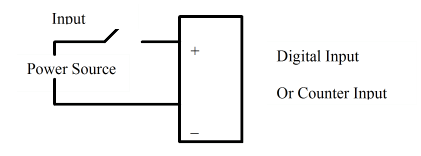
Polarity is important when wiring the inputs. If the Input does not seem to be working, please check the wiring to ensure the polarity is correct.
A typical connection would be as follows:
JNIOR Outputs⚓︎
The JNIOR is equipped with Relay Outputs. Our dry contact relays offer protection from wiring issues but do require that voltage is applied to the circuit. There are 2 or 4 internal FORM C relays depending on the model. The relay can be configured as normally open or normally closed based on an internal jumper.
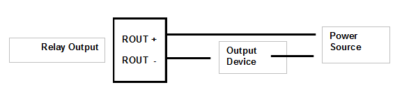
The majority of the relays are Form A SPST relay (1 Normally Open Contact) and two of them are Form C SPST relay (1 Normally Open Contact and 1 Normally Closed Contact – jumper selectable as to which one is available on the JNIOR terminals by removing the lid and changing the jumper setting. Normally Open is the default.) Each relay output is independent and isolated from the other relay output. Each relay contact rating is 1A @ 24VDC and the voltage source must be in the range of 5 – 30V AC or DC. A typical connection would be configured as follows:
The JNIOR is a low-voltage I/O device. Voltages to the internal I/O should be kept to 30 V or less. If you want to control high voltage Outputs, please look at our 4 Relay Output Module.
Setting the JNIOR's IP⚓︎
Starting with JANOS 2.0 OS, the JNIOR is shipped with DHCP enabled for dynamic setting of the JNIOR IP address by a network server. More information is here on finding your JNIOR’s IP address.
If DHCP does not work on your network, then there are two ways to configure your JNIOR IP settings:
-
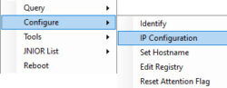
By using the JNIOR Support Tool’s or JNIOR Supporter’s Beacon tab. You can use the JNIOR Support Tool to configure the JNIOR’s IP by right-clicking the JNIOR and selecting Configure -> IP Configuration. A dialog will appear to edit the JNIOR’s IP after that.
-
Via the RS232 Serial Port and a command line window available via the JNIOR Support Tool or JNIOR Supporter. You can use this command line to set the IP by doing the ipconfig -a IP -m MASK command, replacing ‘IP’ with the IP you want for the JNIOR, and ‘MASK’ with the subnet you want for the JNIOR. For example, on a private network, the IP address may be something like 192.168.1.10. A common mask would be 255.255.255.0. The command would then look as follows:
- ipconfig -a 192.168.1.10 -m 255.255.255.0
JNIOR Web Page⚓︎
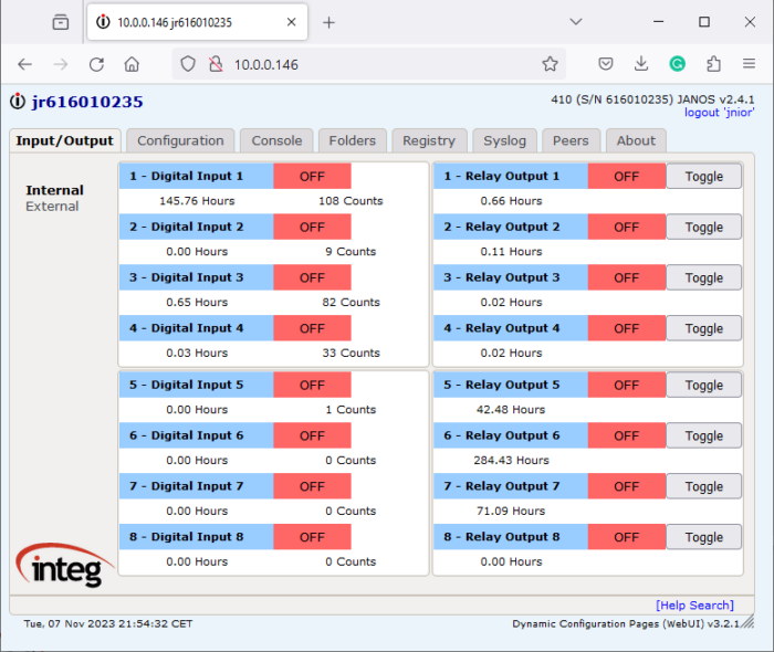
The JNIOR Series 4 contains the JNIOR web page, which is a web page used for various functions, including monitoring and manually controlling the I/O, changing various configuration items, opening a Telnet/Console session, and several other functions.
PLEASE NOTE:
The dynamic web page requires a ‘modern web browser’ which is defined as Internet Explorer 10 or greater, Google Chrome or Firefox.
You can launch the JNIOR web page from the Beacon tab in the JNIOR Support Tool by right-clicking on your JNIOR and going to Tools –> Open web page. To manually launch the JNIOR web page, open your web browser and in the address line type your JNIOR IP address or serial number, for example: http://10.0.0.146 or jr616010235.
After the JNIOR web page is loaded, the user is asked to log in with a valid username and password. You can use the default username (jnior) and default password (jnior).
The JNIOR web page will be launched in your browser as shown below.