JNIOR as a DMX Fixture Revisited
In an earlier article we attempted to connect the JNIOR to a DMX512 network in a way that would allow a theater stage crew to control relays and other outputs through their main lighting control panel. Here with the programmable facet of the JNIOR we could help create complex special effects that can be triggered in-sync with lighting. In fact, DMX channel data can be used by the JNIOR application to trigger and manipulate activity on a LAN segment and thereby update computer screens and TV displays on stage. This can all occur with precise timing in concert with other lighting changes.
The DMX512 protocol and interface was developed over 50 years ago as a means to reduce wiring cost and to improve the mobility needed to support major concert tours in the music industry. It incorporated serial data transmission formats that were state-of-the-art at the time and that are still relevant today. Unfortunately the protocol employed a baud rate much higher than would be later recognized as standard in the computer industry. Also the limited capabilities for data synchronization and lack of error checking make interfacing difficult. Even though the JNIOR Model 410 is able to handle the RS-485 signals and was upgraded to receive 250 Kbaud data triggered on the specified serial Break Condition, we could not achieve reliable operation as a fixture through programming alone.
The issue relates to the design of the standard computer hardware component called the UART. The Break Condition that the DMX protocol uses to identify the start of a frame of data is not handled by the UART in a fashion that can be reliably used to synchronize data reception. At least it is not possible in a purely software implementation as we discussed previously. The answer lies in a simple hardware adapter that alters the DMX512 signals just enough to work correctly through the UART. We will see what that entails in the rest of this article.
DMX512 Fundamentals
Today DMX is defined by official standards. On the wire DMX512 uses EIA-485 differential signaling. We often refer to it as RS-485. You are probably more familiar with the term RS-232. As serial digital communications became more prevalent the distance limitations and noise susceptibility of RS-232 became more and more of concern. The solution, designated as RS-422, used balanced transmission lines over twisted pair which extended the distances that signals can traverse as well as the communication rates that can reliably be achieved. RS-422 connections however are point to point and as computer systems grew so did the need for networking. Soon RS-485 came along and added functionality that created a multi-drop environment where one talker can communicate with a number of listeners. RS-485 is what DMX512 needed where one (or more) lighting control panel must communicate with multiple lighting fixtures.
This basically amounts to a 3-wire network where there is one DATA+ (positive) data line and one DATA- (negative) data line along with a GND ground. The DMX standard details specific connectors (5-pin XLR) and wiring of sufficient gauge and quality. The world also wants to utilize 3-pin XLR connectors for DMX as these are prevalent in the industry through their use in audio applications. You will find a mixture of fixtures some with 3-pin and some with 5-pin connectors. Thankfully 3-pin to 5-pin adapters are readily available.
On the protocol side it was necessary to standardize. This would encourage lighting manufacturers to incorporate the technology. Over the years the protocol itself had been handled by different standardization groups and now is:
American National Standard
ANSI E1.11-2008 (R2008)
Entertainment Technology – USITT DMX512-A
Asynchronous Serial Digital Data Transmission Standard
for Controlling Lighting Equipment and Accessories.
In order to understand where we have difficulty we need to look deeper into the specifics of what is sent across the wires. You recall that DMX was invented to reduce wiring costs. Each channel in the protocol replaces a single power cable. The protocol allows for up to 512 channels and all of those multiplexed onto a single 3-wire network cable. That is a significant savings.
Each channel digitizes an analog signal into one 8-bit value. These can represent numbers from 0 to 255 and for lamps that is used to sufficiently cover the range from 0% to 100% brightness in 256 steps. Where once one channel controlled one lighting fixture, today multiple channels are assigned to each fixture to define attributes such as color and positioning in the case of motorized fixtures. In the serial world each channel is transmitted just as a byte of character data would with a start bit, 8 data bits and one or two stop bits. For DMX512 two stop bits are used. That is a total of 11 bits per channel.
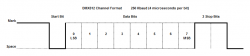
Now with a constant flow of channels each looking the same on the wire how do we know which one is channel 0 and which might be the one we need for our fixture? If we connect to an active DMX network we need a way to synchronize ourselves. For this the standard defines the use of a Break Condition to signal the beginning of a frame. In old days this was called an Attention Signal and it was used to wake up remote teletype equipment and there was actually a key on the Teletype for this. So back in those days this was a natural choice for DMX synchronization. A Break Condition amounts to a period of time where the signalling is held at the level of a Start Bit (Space) long enough to violate the normal byte format and cause a reception error. The receiver simply fails to see the Stop Bits where they are expected and raises a flag. This is intended to signal the beginning of a frame.
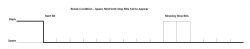
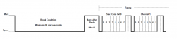
After the Break Condition terminates there must be a brief period of time before the Channel 0 (Start Code 0x00) can be transmitted. This period is called Mark After Break and the current specification defines a minimum of 8 microseconds the time period of two bits. This too has been reduced from prior versions of the specification. A maximum duration of 1 second is defined for Mark After Break and no typical value is given.
Here is what this looks like in reality. The wider pulse in the center is a Break Condition and Frame data can be seen to the right and left of it. Note that in this case all Channels are set to 0x00 and so we see only the Stop Bits for each.
There is one point that I have not mentioned. The total number of Channels included in a Frame is a maximum of 513 but that number is optional. A lighting controller may decide to only send 128 Channels in addition to the START CODE assuming that others are unused and thereby increasing the number of Frames per second. The specification defines a maximum Frame rate of around 836 Hz (Frames per second). This can accommodate fixtures that need higher Refresh Rates. The Refresh Rate for a DMX512 Universe of a full 512 Channels is around 44 Hz.
In the previous article we alluded to there being some difficulty in receiving these signals with standard computer hardware. We now have enough technical detail to understand what that reception problem might be. This is the topic for the next section.
The Issue with the DMX Break Condition
Now let’s look at the task of receiving a frame of DMX data from a software point of view. We will assume that you have configured the hardware to receive RS-485 signals. The JNIOR Model 410 AUX port has RS-485 capability when properly wired and configured. INTEG can provide those details and those are mentioned in other articles. The JANOS operating system has also been enhanced to accommodate DMX and includes the 250 Kbaud rate setting as standard.
In the previous article JNIOR as a DMX Fixture we covered both the proper hardware configuration for the JNIOR Model 410 and the simple Java application software that might be used to receive a frame of channel data. We took that a step further and let the JNIOR activate relays in response to changing channel levels. It is here that we noticed a reliability issue and then spent time to understand it. We discovered that it is a limitation in the design of the standard UART and not something specific to our software or even the design of the JNIOR. Here we will review those findings and then in the balance of this article present a solution.
As you can imagine it would not be acceptable for the JNIOR to receive an incorrect channel value and act upon it. On stage you might create a flicker and distract the audience or worse trigger some elaborate effect at a totally inappropriate moment. Neither contribute to receiving good performance reviews. Well our first attempt at having the Model 410 serve as a fixture worked but occasionally there was a glitch. A relay toggled inappropriately and this lead to an investigation.
We started by attempting to validate the frame of channels. We know that the START CODE should be 0x00. So we decided to first test the START CODE. Well, 0x00 was not what we were seeing and this led us to understand that the UART is not able to properly receive data immediately following a Break Condition. Let’s look deeper into it.
Every description of the inner workings of the UART describes the reception of data beginning with the detection of the Start Bit. They state that “A Start Bit is detected as the falling edge of the signal” (which at that point is moving from a Mark condition to a Space condition from HIGH to LOW). This makes sense since this can be used to synchronize the baud rate and the UART once detecting the falling edge delays 1/2 bit time to begin sampling. The first reading is then LOW (0) since it is a start bit.
The UART then can proceed to receive data bits one after another starting with the LSB (Least Significant Bit or D0). Let’s assume that we are configured for 8 data bits and no parity as is the case for DMX. Once all 8 Data Bits are collected and the byte of data fully accumulated then next bit sampled is expected to be HIGH (1) as this is the necessary Stop Bit. The UART sees the Stop Bit and pushes the data to the output buffer and notifies the system that data can be read from the port. You can see how this follows from the first figure in this article repeated here.
We mentioned previously that in the case of a Break Condition the Stop Bits are missing. Here the UART receives 8 Data Bits or what it hopes are 8 Data Bits and then fails to detect the Mark condition signalling the presence of a Stop Bit. The typical UART then pushes the data to the output buffer and signals the processor that data can be read from the port. It also sets a Framing Error flag and well-written serial drivers handle the error accordingly.
Here is where your logical thinking might fail you. Once the UART signals a framing error you would like to think that it reenters the aforementioned ‘Start Bit Search Mode’. This would take the UART through the balance of the Break Condition and past whatever Mark After Break is present to the very next falling edge of the signal. This then allowing it to reliably and properly receive the very next valid byte of data. Well, surprise, it does not work that way.
Instead the UART continues to sample bits based upon its internal baud rate clock. It accepts the very next LOW (0) bit as a Start Bit and proceeds to process the following 10 or 11 bit times as another byte of data. This is why from the software side a Break Condition usually presents itself as more than one 0x00 byte each with an associated Framing Error. By itself this is not an issue as you can accept one or more Framing Errors as an indication of the Break Condition. In fact you could use this to detect a short Break from a long Break. But let’s look closer at what happens at the very end of the Break.
At the conclusion of an arbitrarily long Break Condition the signal returns to a Marking state. We have reached the Mark After Break but it is highly likely that the UART is still accumulating hopeful data bytes. Eventually it sees the Mark as a valid Stop Bit. The result is that a byte is then output by the port and there is no Framing Error. There is no way for software to determine if this is the first valid data byte (START CODE) or a bogus trailing byte formed out of the end of the Break Condition.
In testing we can see that this indeed is occurring. Since data bits are transmitted from least significant to the most significant, depending on signal timing this bogus byte can be seen to contain any one of the following: 0x00, 0x80, 0xC0, 0xE0, 0xF0, 0xF8, 0xFC, 0xFE or 0xFF. Perhaps you can see that this result depends on just what Data Bit the UART thinks it is receiving at the point when the Mark After Break begins. There is actually one additional case and that being when the data is actually the first valid data byte after the Break. This effect depends highly on the duration of the Mark After Break as well.
Matters can be even worse. In DMX512 the Mark After Break can be as short as two bit times or 8 microseconds. That means that it is possible that the UART does not even look for a Stop Bit until the signal is deep into the START CODE byte. Since the START CODE is itself 0x00 the UART might then grab one of those data bits as a Start Bit and, well, fail to receive several channels of data. How can this be? Are UART designs defective?
Well let’s not jump to that conclusion just yet. Let’s give the hardware developers the benefit of the doubt at least initially. First we should understand that once the computer industry embraced serial data communications use of the Break Condition fell by the wayside. Protocols used Start of Header (SOH) bytes and other means for synchronizing data blocks. These tended to include byte counts, error checking and even error correction. These days there is even data compression and data encryption. The Break Condition not only fell out of use but also started to disappear from serial communications documentation.
Meanwhile the industry started to look into the reliability of data transmission lines. In the early days RS-232 cabling was not what it is today and it was very susceptible to external electrical noise. Also remember that we were still using machines developed in the early half of the 20th century. These were power hungry electro-mechanical contrivances that spewed out electrical noise with reckless abandon. RS-232 signals often experienced data disruptions some as brief as an incorrect value of a single bit up to the loss of entire blocks of bytes. There were even situations where communications were completely blocked out for lengthy periods of time. Perhaps for as long as the nearby noisy equipment remained in use. This led to better cabling. It led to improved communications standards like RS-422. It prompted the need for error detection and motivated a lot of creativity on the error correction front. Simultaneously the Federal Communication Commission (FCC) put forth standards for controlling RF and electrical noise emissions and prompted certifications making new equipment meet the stringent requirements.
A UART design that utilized a “Start Bit Search Mode” fails to perform properly in a noisy environment. In the case when a Stop Bit is damaged by noise and thereby missed by the UART, an approach that accepts the very next falling edge as a start bit falls on its face. It fails to re-synchronize quickly. Many bytes of data then are lost even though electrically the signals are undamaged. Error correcting schemes just could not handle it. They determined that the current UART approach performed much better and, well, what is this Break Condition anyway?
We can only guess at how we got to where we are today. It is actually a surprise that a 50-year old protocol would still be as active today and it would still rely on synchronization techniques like the Break Condition. Of course it is not really an issue as DMX fixtures are developed to properly receive these signals. We are just a bit hampered in trying to use standard computer hardware. So what can we do about it? That is our next topic.
Correcting the DMX512 Protocol
We stand little chance of “correcting” the DMX512 protocol. With over 50 years worth of legacy DMX equipment out there a change in the design of the protocol is just not an option. The ability for DMX to inter-operate with standard computer hardware is just not that critical of a need. We have also exhausted any possible software solution to this issue. So what can we do? Some kind of hardware solution will be needed if we want to develop a JNIOR that can be used as a DMX fixture. What form will that take?
Obviously lighting fixtures all over the world read DMX channels seemingly without difficulty. So we know we can do it. Does this require a custom UART implementation in some FPGA component? Do we have to dedicate some PIC processor or other device to process incoming DMX bit by bit? Are there standard DMX chip level devices out there to make it easy? It certainly all cries out for some research. But first let’s see if there is some simple and creative way to address the issue.
The problem breaks down into two separate issues:
- The UART is unable to synchronize after a Break condition and reliably read the first START CODE byte.
- The trailing edge of the Break Condition can generate unexpected data not identified with a Framing Error.
Clearly if we use a Framing Error indication to signal the reception of a Break Condition and we are 100% assured that the next valid data byte is accurately representing the START CODE we are good to go. We assume then that the processor has enough horsepower to receive and buffer all 513 channels (if they are present) without error. This can be done with low-level interrupt routines avoiding any dependence on the processing load in the JNIOR. In fact all of this has already been implemented in JANOS and deployed into the field. Those techniques were tested in the prior article.
The Mark After Break condition specified by the DMX512 protocol is a minimum of 8 microseconds. That is just two bit times. This is unfortunate. If this Mark After Break condition were to be held at least 11 bit times (44 microseconds) then any UART would be assured of seeing some part of the condition as valid Stop Bits. The UART then would be guaranteed ready to receive the very next data byte which is the START CODE.
If we somehow could extend the Mark After Break that would insure the reliable reception of the channel data. That by itself is not enough since we know that the trailing edge of the Break Condition can generate a data byte that is not flagged with a Framing Error. This would confuse us as there is no real way to determine if this is the START CODE or a bogus addition to the stream.
Now if we could somehow limit the Break Condition to a single byte we would receive one and only one byte flagged with a Framing Error. The UART would not see an additional Start Bit and thereby insure that the next byte we see is in fact the START CODE. We know that the Break Condition is at least 88 microseconds at its shortest. That is exactly two data byte times (each of 11 bits = 1 start bit + 8 data bits + 2 stop bits). So if we truncated the Break Condition at exactly 44 microseconds which would generate 1 byte with a Framing Error, there is another whole byte’s worth of time that could be added to the Mark After Break. This would satisfy our interest in extending the Mark After Break for at least a byte time. At a minimum it would then be 52 microseconds (44 borrowed from the Break + 8 original microseconds).
The Hardware Solution
Our hardware needs to truncate the Break Condition. We need only hold it long enough to mask the first Stop Bit and thereby force the Framing Error. This needs to be achieved without risk of causing other Framing Errors. With a little thought we developed the following logic.
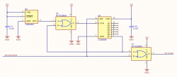
The CD4024B (U6) is a 7-stage counter and it is reset (RST) or restarted with any HIGH Marking condition on the incoming data. This means that the count is not allowed to progress very far except during the Break Condition where there is no reset (RST). This in essence times the duration of the Break Condition. Note that when the output of the 7th stage goes high (count >= 64) the OR gate then pulls the TXD signal high effectively truncating the Break Condition. The signal output is then held HIGH until the Mark After Break arrives and resets the counter. At this point the incoming signal is HIGH and we have effectively transferred time from the Break Condition to the Mark After Break. This is exactly what we want.
The UART will throw the Framing Error as soon as the first Stop Bit is not detected. We don’t want it to see any potential Start Bit after that. To be safe then we truncate the Break Condition after the 10th bit time right after the first Stop Bit. This means that we must truncate the Break Condition precisely after 40 microseconds and this must occur at the 64th count when the 7th stage goes high. As it turns out 40 microseconds divided by 64 is 0.625 microseconds the precise period of a 1.600 MHz clock. Those are readily available. So we clock the counter with a 1.600 MHz signal using oscillator U4.
One last detail to consider. There is no upper bound on the duration of the Break Condition. That means that once we truncate the Break Condition we need to hold it for potentially a very long time. So we cannot allow the counter to continue to run. Once the 7th stage goes HIGH we need to hold it there. A second OR gate (U5) masks the incoming 1.600 MHz clock signal at that point effectively stopping the counting. And, miraculously, we’ve got it covered.
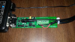
To test this we created a prototype adapter which implements an isolated DMX512 standard port. The signal passes through our circuit and then a standard RS-232 transceiver is used to communicate with the JNIOR AUX port. One advantage this has is that any Model JNIOR with an AUX port can be used as a DMX fixture. Whereas only the Model 410 supports RS-485 directly and can be used as described in the prior article.
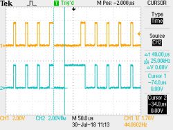
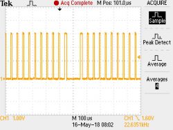
On the yellow trace we see that the Break Condition supplied by the DMX network is about 100 microseconds and it is followed by a brief Mark After Break which looks to be somewhat less than 50 microseconds. We know that this signal is problematic as it is from the same source used in the prior article. Note here that the START CODE and all channels happened to be 0x00. So those high pulses are Stop Bit pairs.
Now the blue trace is the result. The Break Condition has indeed been truncated. The vertical cursor lines are positioned to measure the duration of the new Break Condition. On the right we see the delta-t to be the precise 40 microseconds we had hoped for. We can also see that the balance of the time in the Break Condition has now been added to the Mark After Break.
Does this allow the JNIOR to be used as a DMX fixture? In fact it does and there is absolutely no glitch or reliability concern. Here is a short video showing relays responding to a DMX channels. A channel value greater than 127 is used to signal closure of a relay. The JNIOR’s 8 relays are mapped to consecutive channels.
Of course this would need to be evaluated with a wide range of DMX512 signal sources. The Java application on that JNIOR in the video is essentially that discussed in the previous article. It would be useful to reiterate its operation but that is beyond the scope of this article. If you should be interested in using a JNIOR as a DMX fixture just let us know. We can likely supply you with one of these prototype adapters and the application programming is open source from us. If you already have a JNIOR then your are almost there.
We should note that not all UARTs are created equal. There are likely UART implementations that do properly handle synchronization after the Break Condition. If you have one of those then you are golden. In the case of the JNIOR we were not so lucky. While the adapter was described above as prototype we do have several that we can supply. It is not clear that there would be any long term demand for this. A model of the JNIOR directly providing a DMX512 electrically isolated input is now feasible and would likely include the circuit as described here. Contact INTEG to find out more.
Update
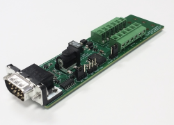
We can provide the adapter (as shown) along with a power supply and instructions. The adapter can be used in any serial application and not just with the JNIOR however as discussed in the article you would need to accommodate the unique Baud rate and trap the framing error for synchronization. The document supplied includes an example application for the JNIOR and a schematic.
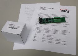
Note that straight-thru terminals are provided allowing you to tap either 3-wire or 5-wire DMX signals. You may wish to splice into a DMX extension cable (not provided) to give yourself cabling terminated by the desired (3 or 5 pin) DMX XLR connectors. An isolated DMX port is implemented and so your JNIOR or PC is not directly connected to the lighting system.
The above kit is INTEG P/N A00-00155 – DMX512 SERIAL PRE-PROCESSOR.