Using Serial Control Plus
Serial Control Plus is an application from the Bundled Applications update project. It allows you to connect serially or through TCP to a JNIOR, and give it commands to activate the JNIOR’s I/O. This post will explain how to set up and use Serial Control Plus on your JNIOR.
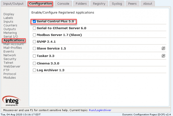
Enable Serial Control Plus to run on boot.
To activate Serial Control Plus, go to the JNIOR’s Web Page. This can be accessed by either right-clicking the JNIOR in the JNIOR Support Tool and going to Tools/Open Web Page or by typing the JNIOR’s IP address into the URL of your computer’s web browser. Once there, you’ll go to the applications section on the configuration tab, click the checkbox next to Serial Control Plus, and reboot your JNIOR. This will allow you to use Serial Control Plus on that JNIOR.
Configuring Serial Control Plus
Once Serial Control Plus is started, we’ll review some of the JNIOR’s configurations to connect with it. We’ll go to the Registry tab of the JNIOR Web Page, and then navigate to AppData/SerialControl registry folder.
NOTE: If the AppData/SerialControl registry folder does not exist, it may be because Serial Control Plus needs to run first. Reboot the unit and then refresh the webpage and the registry folder should appear.
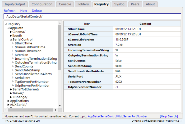
If using a serial connection with the JNIOR, you’ll want the SerialPort registry key set to whichever serial port you are using. AUX is for the auxiliary port and COM is for the RS-232 port. If using TCP or UDP, make sure a port number is set for the TcpServerPortNumber or UdpServerPortNumber registry keys. These port numbers are what other devices need to send to communicate with the Serial Control Plus application.
Once these values are set, if using a serial connection you’ll need to navigate to the Configuration tab and access the Serial I/O section. Otherwise, if you made any changes to the registry keys for Serial Control Plus you need to reboot the JNIOR so those changes take effect.
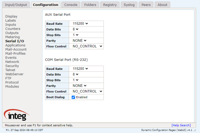
In the Serial I/O section, you’ll check the settings of the serial ports for the JNIOR. These should match the serial settings of whatever device is trying to communicate with the JNIOR, or else the data coming in through the serial ports won’t be correct. If you are using the COM port, make sure that you disable the boot dialog by unchecking the Boot Dialog checkbox. If you change any of these settings, make sure that you reboot the JNIOR so they take effect.
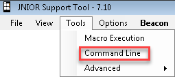
Once you have activated the Serial Control Plus application on your JNIOR and the settings of the serial ports are correct, you can now send commands to the JNIOR through it. We will open the command line from the support tool to activate commands on this JNIOR for this example. To open the Support Tool’s command line, go to the Tools -> Command Line at the top left of the Support Tool.
NOTE: As of Support Tool 7.16, the command line has been replaced with a PuTTY terminal. Connection configuration should now be done through the PuTTY Configuration dialog before the terminal is opened. If PuTTY is installed, the PuTTY Configuration dialog will launch from the Tools -> Command Line option.
Once you have the command line open, you’ll need to configure the settings of the command line to send commands to the JNIOR. To have the right settings to communicate with the JNIOR, we need to select how we communicate with the JNIOR. Serial Control Plus can communicate with the JNIOR in two ways. Either you can connect to the JNIOR with a serial connection or a TCP connection.
To connect serially with the JNIOR, plug a serial cable into the serial port you set in Serial Control Plus’s registry. Then make sure that the command line connection settings match the serial settings setup in the Serial I/O section of the Configuration tab of the JNIOR Web Page from before.
To connect through TCP or UDP, you just need the JNIOR to be on the network to connect. For your command line connection, make sure it’s set to a TCP or UDP connection (whichever one you are using), and that the port number matches the port number you set in the Serial Control Plus registry.
Once you’ve decided on your connection type and configured the command line accordingly, you should be able to send commands to the Serial Control Plus application. Here are commands for controlling and monitoring I/O.
Controlling I/O
The following commands can be used to close, open and pulse outputs.
cX: Close the output (relay is “on” closing the contact)
where x = 1 through 8 for the internal relay outputs on the JNIOR
and x = +1 through +8 for the external relay outputs on the 4 Relay Output Expansion Modules
oX: Open the output (relay is “off” opening the contact)
where x = 1 through 8 for the internal relay outputs on the JNIOR
and x = +1 through +8 for the external relay outputs on the 4 Relay Output Expansion Modules
p=yyy Pulse duration (milliseconds) and is used in conjunction with the ‘close’ or ‘open’ command
Examples:
c2p=1000 close output 2 for 1 second and then open again
c+2p=1000 close output 10 for 1 second and then open again
o3p=10000 open output 3 for 10 seconds and then close again
c* Close all outputs at the same time (includes internal and external)
o* Open all outputs at the same time (includes internal and external)
These commands can be abbreviated and used in combination, such as:
c1 close relay output 1
c+1 close relay output 9 (first output on first expansion module)
c+5 close relay output 13 (first output on second expansion module)
c1+1+5 combination of the above all in one command
c1234 close relay outputs 1 through 4
c1368 close relay outputs 1, 3, 6, 8
o125 open relay outputs 1, 2, 5
c1+1p=1000 close relay outputs 1, 9 and pulse each for 1 second simultaneously
Monitoring I/O
Whenever an input (or output) changes status (low-to-high or high-to-low), the following is sent out by the JNIOR:
INx=1 Input x (1 – 8) has gone high (on)
OUTx=1 Output x (1 – 16) has gone high (on)
INx=0 Input x (1 – 8) has gone low (off)
OUTx=1 Output x (1 – 16) has gone low (off)
The default setting for the Registry Key AppData/Serial_Control/SendCounts is false. If you change this key to true and reboot, with each message stating the input status, a count value will also be included. Whenever an input changes status (low-to-high or high-to-low), the following is sent out by the JNIOR:
INx=1,yyy Input x (1 – 8) has gone high (on), counter value = yyy
INx=0,yyy Input x (1 – 8) has gone low (off), counter value = yyy
Note: These monitoring messages are sent out individually over the serial port or Ethernet. The JNIOR does not report the status of more than one input/counter in the same message.
With this, you should now be able to use Serial Control Plus to control and monitor a JNIOR’s I/O!