JNIOR Serial Ports
The JNIOR Model 410, 412 and 412 each have two available serial ports. Each port providing at least a 3-wire RS-232 interface. A 3-wire connection contains only the Transmit (Tx), Receive (Rx) and Signal Ground (GND) circuits. This is the bare minimum for Duplex communication or interfaces utilizing software handshakes. The Rx line may be omitted if only sending data. Similarly the Tx might be omitted if only receiving data.
In addition to the 3-wire signals the AUX port supports optional hardware handshaking using the Request To send (RTS) and Clear To Send (CTS) signals. The Model 410 AUX port also provides a configuration for RS-422 and RS-485 communications.
While there are a number of parameters that must be properly configured in order to achieve functional and reliable communication, the biggest issue is (and has always been) proper cabling. If an RS-232 connection is not working and it is the first time the connection has been made, the connections are probably not correct.
Originally the RS-232 standard was created to support the connection of a modem. Before networking the modem was used to extend communications over standard telephone lines. Typically a computer (an IBM 360 for instance) would connect to a modem. At home a user would connect their terminal to another modem and establish a remote connection via dial-up. There are two types of equipment in this scenario: the computer stuff and the communications stuff (modems). The RS-232 standard defines two acronyms for this: DTE and DCE. These are used extensively to define connector types and signal definitions.
This is where the confusion begins. The acronym DTE refers to Data Terminal Equipment and in our example above this includes both the Computer and the Terminal (CRT or Teletype). That would be the stuff that you would be trying to connect together had you not needed the modems. The term DCE is often confused and is meant to refer to Data Circuit-Terminating Equipment or Data Communications Equipment. That being the modem in the above example. It does not stand for Data Computing Equipment which implies the computer. These terms are often confused and, perhaps, never really understood. As a result even the engineers who design the equipment (including myself) often employed the incorrect connectors, signal terminology and pin assignments. So let’s not use these designations.
JNIOR Serial Ports
The JNIOR has a COM port (labelled RS-232) and an AUX port (labelled AUX Serial). Both are DB-9F Female 9-pin D-sub connectors. The AUX port has 4 active signals and the COM port 2. The pin assignments are as follows:
2 >> RS232 TX / RS485 TX-
3 << RS232 RX / RS485 RX-
5    GND
7 << RS232 RTS / RS485 RX+
8 >> RS232 CTS / RS485 TX+
Here is how it shows on the schematic. Note that even the pin numbering on the the connector itself can be confused. The (>>) indicates an output. The JNIOR generates a voltage on this pin and it must be connected to an input at the other end. The (<<) indicates an input. This should be connected to an output at the other end. We will cover RS485 in a little bit.
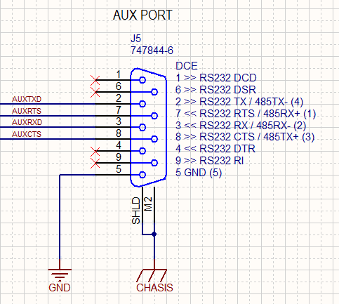
You can see that we do not use DCD, DSR, DTR and RI. These are unconnected. The COM port follows the same assignments but ONLY pins 2, 3, and 5 are used.
Here is the source of additional confusion. The JNIOR transmits data on Pin 3 and therefore from the JNIOR’s point of view THAT is Transmit Data (TX or TxD). But when that signal reaches the other end (say your PC) it is incoming data or Receive Data (RX or RxD). That is because from the point of view at the PC it is data that would be received. So you connect RXD to TXD and visa versa.
Not everyone labels it that way. You will find an input pin labelled TxD. The thinking is that you would connect TxD to TxD. After all you do connect CTS to CTS as the signal is Clear To Send regardless as to who generated it and who is listening to it. The same goes for Request To Send (RTS).
It is not surprising that we sometimes have to grab a voltmeter to see if a pin is generating an RS232 voltage level (an output) or not (an input). Even that can be misleading when pull-up resistors are used. I used to have a couple of really sweet RS-232 break-out boxes. Those have gotten lost but were life savers back in the day. You know, nice colored LEDs showing outputs and jumper wires that you could use to test various cabling solutions before soldering the final cable.
JNIOR to PC Connection
Well today if you want to connect the JNIOR to your PC you will need a USB-To-Serial adapter. You would likely want to do that to gain access to the JANOS Console (command line interface) available over the COM port (115.2Kbaud, 8 data bits, 1 stop bit, no parity). The adapter will present you with a DB-9M Male connector identical to what you would have found on an older PC as a COM or AUX port connection. The connector (DTE) can be directly plugged into the JNIOR COM (or AUX) port (DCE).
Some USB-To-Serial adapters provide a length of cable and others are relatively short. If you need a longer cable then you either use a USB extension or an Male-To-Female Straight-Thru Serial Extension cable. The latter would need only be 3-wire unless your application optionally employed the hardware handshake. I will cover that a little later.
You would use this same approach to connect the JNIOR’s AUX port to a PC-based media server or other system that uses the standard PC serial ports. An application on the JNIOR can then send and receive data or commands to the remote server.
Connecting a Device to the JNIOR
If you plan to connect a barcode scanner or other device to the JNIOR then you might need a little help. You may need a 9-pin Gender Changer. There are two kinds: F-F and M-M. You may need the Male-To-Male (m-M) Gender Changer. This has pins on both sides and when plugged into the JNIOR it changes the connector from a Female DB-9F to the equivalent of a Male DB-9M. Unfortunately this does not alter the pin assignments and if the device was designed to be plugged into a PC then you will need a cross-over adapter or cable. The cross-over exchanges pins 2 and 3 (as well as 7 and 8). Remember that you want to always connect an output to an input. Sometimes this is called a Null Modem adapter, the name coming from the need to interconnect two DTE devices without modems.
Perhaps in hindsight it would seem that the JNIOR AUX port should have been DTE. In fact in the beginning we did not use a DB9 connector at all and provided screw terminals for the 5 signals since we would be required to connect to either DTE or DCE. The reality is that in Cinema (which was an early and big market for JNIORs) we connected often to media servers (which are essentially PCs) and the current DCE arrangement worked best for those customers. That stuck.
So as a result you end up with stuff like this.
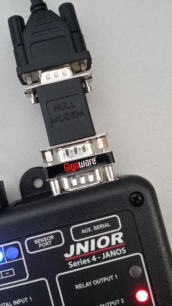
Of course if you are handy with the soldering iron and get some solder-cup DB9 connectors and hoods from Digi-Key, you can clean this up nicely. They had hoped to solve all of this with USB but that has created other issues.
It didn’t help RS-232 that from the beginning no one fully understood how to document it. Some of us might remember the detailed signal diagrams explaining plus and minus 12V states, start and stop bits, and little endian order in the back of manuals. That level of detail was just adding to the confusion.
Here is a modern day failure. This is from a product received in 2017. At first glance you would think this is good documentation.
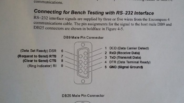
Here only the boldface signals are available or can be used. Perhaps only those should be shown. But beyond that picky item the important piece that is missing is any indication or what is an output and what is an input. You can naturally make your own assumptions. You might correctly assume that Received Data (RxD) is information generated (or output from) the remove connection and therefore an input at this connector. The TxD would then be an output. I mean you only have two choices here and chances of being correct are 50/50. If you are working a soldering iron though you won’t appreciate making the wrong guess.
It is not so obvious as to whether the CTS or RTS connection is an input or output. These signals are shown here but are they used? Are they required? Is there an option setting some place of which you should be aware?
So if you have the diagram for the other piece of equipment that you are connecting should you wire straight thru? Do you wire TxD to RxD and vice versa? If that ends up crossing over from pin 3 to pin 2 and vice versa should you also cross over RTS and CTS? Who knows. RS-232 failure.
My point though is that this nice little picture doesn’t eliminate the chance that your cabling or the cable you make might not work. And, if it doesn’t work you don’t have enough information to decide what to change. Come on man! You can do better.