JNIOR Connectors
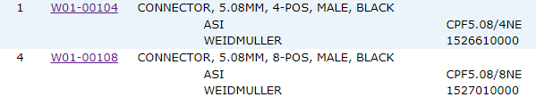
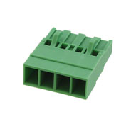
The JNIOR Connector Kit contains 5 connectors. Four (4) are the 8-position female screw terminal types for I/O connections and one (1) a 4-position connector of the same style for the power connection. The latter will also be found on power supplies that are obtained from INTEG. here are the part numbers.
They look like this. The others having 8 positions of course.
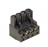
These are SINGLE ROW FEMALE TERMINAL BLOCK PLUG 0.200″ 5.08MM PITCH. Color is irrelevant although INTEG tries to supply BLACK for digital signals and power, and GREEN for analog (external modules).
There are alternatives to these connectors that you can source separately. INTEG does not stock an alternative although arrangements can be made upon request.
Connectors are generally an expensive part of the product. These two-part connectors add value to the JNIOR.
Some wiring hints…
If multi-strand cables are used it is recommended that either the stripped end of the wire be properly tinned or some form of crimp pin be employed. If neither is convenient then insure that the stripped wire is tightly and cleanly twisted and clamped securely by the connector. Cables should have sufficient slack so as to not stress the connection as connectors are inserted or removed. Ty-wrap cables for a single connector together within 3″ of the connector to provide strength in numbers.
If solid cable is used then it is important that cables have sufficient slack so as to not bend the cable at the connector when the connector is inserted or removed. Ty-wrap cables for a single connector together for added protection.
Screw terminals should be hand-tightened strongly. Periodically check screws and tighten as necessary. Repeated changes in temperature can over time loosen screws.
Clamping more than one cable at a connector position is not recommended. In this case the clamping mechanism will grab the largest diameter wire more strongly creating an intermittent and loose connection with the other. If you must chain wiring in this fashion either tin wires together or tightly and cleanly twist them before clamping. Carefully wiggle both wires separately to insure that both have been securely captured.
When stripping wire use the proper tool with the proper wire gauge setting. Be careful not to cut into the copper conductor. This is highly likely if using a knife to remove the insulator. This can completely cut outer strands of multi-stranded cables reducing their current carrying capacity and increasing the possibility of a poor connection when clamped. Over time as cables are flexed cables that are improperly stripped will tend to break where the insulator has been cut.
If your wiring reaches the JNIOR from above you may consider a connector style where the cables leave the connector at 90 degree angles. For example you can source connectors like this one.
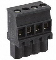
This is Pheonix part nubmer 1836901 and these are available from other manufacturers.
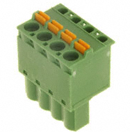
There are screwless connectors. These use spring force to achieve clamping and have the advantage of not loosening over time. There are different approaches. Here is one example.
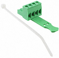
If strain relief is an issue it is best to secure the cabling to the connector. An arrangement like this can be helpful. This eliminates the flex at the cable end where wires may break or loosen.
Now if you are willing to carry another crimping tool you can take a different approach. This would be much more appropriate when the JNIOR is installed within another product or rack mounting. Here you by just the housing and crimp a pin on each wire which is then inserted.

Here there is no question of loosening and strain relief is built-in. That assumes you are proficient at crimping. This is Pheonix 1808832 and I will attach the data sheet as well.
If you are using the JNIOR PCB without the housing as part of your product and are will to purchase in quantities of say 100 and allow for a standard lead time we can accommodate any connector arrangement. The PCB holes are on 0.200″ (5.08mm) centers.
Depending on the commitment we can also create a custom PCB to meet your specific needs. This is not as expensive as you might think. Cost does depend on quantity. Call us. We are willing to work with you.
There is no cost in asking.