Relay Output Overview
Series 4 JNIORs have a varying amount of inputs and outputs depending on what model you have. The 410 has 8 inputs and 8 outputs, the 412 and 412DMX have 4 inputs and 12 outputs, and the 414 has 12 inputs and 4 outputs. Each relay contact rating is 1A @ 24VDC and the voltage source must be in the range of 5 – 30V AC or DC. The JNIOR uses a 2-piece terminal connector system for all power and I/O wiring connections allowing for easy installation and/or removal of the JNIOR.
Controlling Relay Outputs
When controlling the JNIOR’s I/O, the JANOS class can be used to get/manipulate their statuses. In the following example the JANOS class is used to pulse outputs, get the output states mask, check the status of an output, and check an outputs usage meter.
View on GitHub
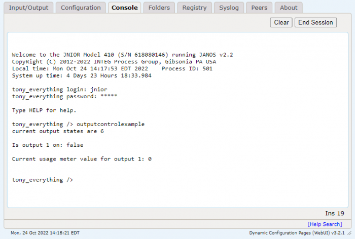
I put the built jar file of this example application into the JNIOR’s flash folder and ran it from the Web UI’s console tab. As you can see it displays different data about the outputs at the time of the application running.

Getting Outputs from the IO Log
Another way to interact with the I/O on the JNIOR is via the Iolog Monitor. The Iolog Monitor is an object that can be checked for I/O events that have occurred on the JNIOR. There is the IoEvent class and Iolog class. An IoEvent is when an input or output state changed on the JNIOR, and the Iolog is an object that contains all the IoEvents from a certain timestamp. The example below pulses an output, and then shows how the Iolog has recorded that output pulse as an IoEvent.
View on GitHub
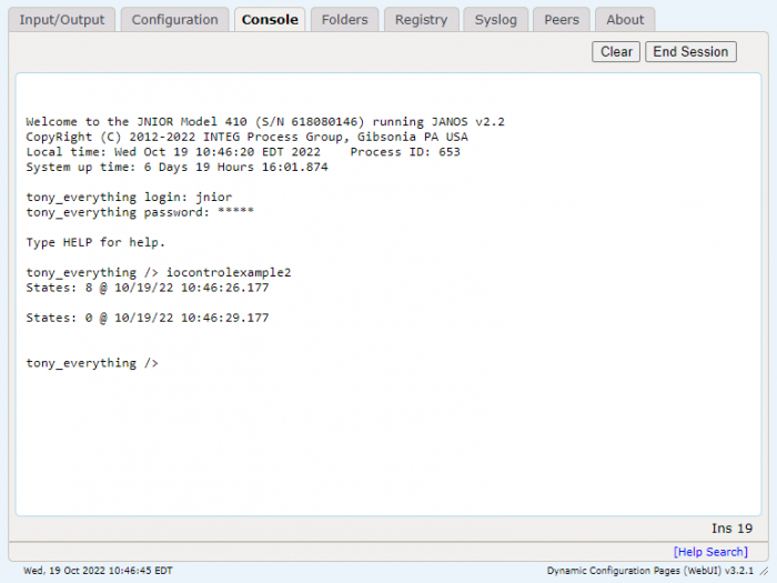
I put the built jar file of this example application into the JNIOR’s flash folder and ran it from the Web UI’s console tab. As you can see it recorded the output change where output 8 turned on and again when it turned back off.

