Powering the JNIOR
The JNIOR uses a 2-piece terminal connector system for all power and I/O wiring connections allowing for easy installation and/or removal of the JNIOR. Additional installation information and drawings are provided on our website.
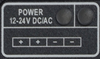
The JNIOR can be powered with 12 to 24 volts AC or DC. An optional, wall transformer (AC power converter) for North American outlets is available from INTEG that can be used for converting 120/240 VAC to 12 VDC @ 1 amp. International models are also available as Euro and UK plugs.
The Power Connector is located along the upper left edge of the JNIOR. Note that this is a 4-pin connector. If numbered from one (1) through four (4) from left to right power is always connected to positions 2 and 3 (middle two connectors). The polarity is irrelevant although it is recommended that the positive (+) lead be connected to position 2.
The left two positions (1 & 2) are internally connected together, as are the right two positions (3 & 4). This is to facilitate the interconnection of the supplied power to other devices and circuits such as input or output devices. If you power the I/O circuits with your JNIOR power supply, please make sure the power supply is sized appropriately.
WARNING: Do not connect the transformer leads both to Positions 1 & 2 or both to positions 3 & 4. This will short the transformer and possibly damage it and/or the JNIOR. Always use a fused/protected power source.
When a proper power source is connected and turned on the leftmost LED adjacent to the power connector will glow BLUE continuously. The LED to the right may glow ORANGE for several seconds. This orange STATUS LED remains on through most of the JNIOR boot sequence. Later it will flash whenever an external connection is made to the JNIOR via the Ethernet port.