JNIOR Monitors Solar
Summary: Generating electricity from sunlight is only part of the challenge. Operating large-scale solar installations requires continuous monitoring, timely alerts, and reliable control. This article explores how JNIOR provides the edge intelligence needed to turn solar generation into dependable, manageable infrastructure.
Solar energy has bathed our planet for eons, and humans have utilized this resource in many ways. However, the ability to harness the sun’s power as a renewable energy source by converting sunlight into electricity is a much more recent development that has become quite commonplace. One challenge is doing so at the scale needed for a home or business to overcome a complete dependence on electrical utilities, and this task has often required users to obtain expensive and inflexible packaged systems.
This paradigm is changing for many users because solar panels and associated electronics are now available so users can incorporate the best options to meet their needs. An investment in a solar installation can offset or eliminate the need to purchase electricity, relegating the power utility to a backup role. In fact, it is possible to routinely generate more electricity than can be consumed, exporting that power back to the electrical grid, and thereby generating a credit to offset installation and operating expenses. This is to say nothing of the ecological value to our planet.
No investment is made without hope for a reasonable return, and typical solar system providers provide some level of status monitoring with their equipment. But this is not necessarily enough, and for those users demanding a bit more flexibility and sophistication, a capable digital platform for monitoring, control, and data access is needed. For those users looking to take full control and advantage of a solar installation, or indeed any modestly-sized system, a compact and capable automation controller can provide just the right degree of supervisory control and data acquisition (SCADA) functionality, without the lock-in and overhead of traditional systems suppliers.
Solar installation fundamentals
Solar installations include certain basic features. The solar panels themselves can be installed in arrays or groupings that are ground-based, or perhaps on top of roofs or other structures. The panels are connected to inverters, whose purpose is to produce electricity compatible with the power grid (Figure 1). One or more batteries may be included to store and distribute electricity locally, which is especially useful if the power grid fails.
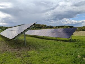
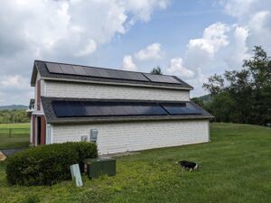
Figure 1: Typical solar installations may include arrays of solar panels installed on the ground or other structures, typically connected to inverters which create grid-compatible electricity. A complete view of all active elements is needed to obtain best overall performance.
While there may be separate means to monitor each inverter and battery system using a mobile app or web-based interface, there likely is no cumulative record of power generation, nor actual power use by the property as a whole. Overall status, supply, consumption, both onsite and in relation to the utility, is needed to truly track energy independence. Real-time information is necessary for tuning power use to make the solar system more efficient.
At one residential site, the user had installed each of the noted solar power elements, in each case choosing the preferred products and vendors to fit the need. The ground-based solar panels supplied electricity to the grid, while the rooftop panels were integrated with a battery systems (Figure 2).
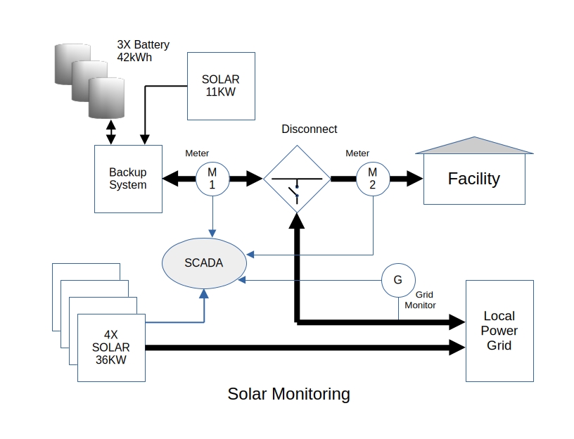
Figure 2: This diagram depicts 36kW of grid-connected solar, 11kW of rooftop solar supplying a battery backup system, and their interconnection with the facility and the utility. A SCADA system was needed to monitor overall operations.
Once the system was completely commissioned and online it worked well, but there was no single interface to evaluate overall performance. This end user was aware that a custom SCADA system could do the job, but they were unwilling to foot the development and ongoing licensing costs for such an endeavor.
Creating a smarter solar PV system
Seeking a simpler SCADA solution, the first step was to evaluate available communication connectivity. The inverters for the ground-mounted array were found to support the MODBUS communication protocol, so they could supply power data to a compatible digital system. The battery backup system, unfortunately, was a closed system offering no data communications without additional expense, and would only provide a status via a mobile app.
To overcome this form of vendor lockout, it was determined that inexpensive power meters with digital communications could be installed on both the utility and facility load sides, measuring how much power was provided by the battery backup system and how much was consumed by the facility itself. Naturally, the power utility’s meter can only be electronically read by the power company. Fortunately, the power readings from the inverters and the meters are sufficient to calculate the flow of power either imported from, or exported to, the power company.
There was only one other status point needed. When the grid goes down, the battery backup system isolates the facility to seamlessly supply site power. It is not possible to determine the grid status from the power meter readings, so a simple line voltage monitor connected on the grid side measures voltages across all phases and provides a dry-contact signal if low voltage indicates a grid failure.
Choosing a streamlined SCADA platform
The SCADA system for this solar installation needed to provide visualization of real-time status and historically trended data for all elements. A flexible way to achieve this goal is by using a platform able to serve up dynamic internet-accessible web pages. The platform would need to connect to the various data sources using digital communications and hardwired input/output (I/O) signals, and it then preprocesses the information and presents it in web page format.
For a local interface, it was desirable to have a simple stacklight, providing the following at-a-glance indications:
- Green: power is being exported to the utility
- Yellow: power is being purchased from the utility
- Red: there is a utility outage
- Beeper: sounds when there is a utility outage
While consumer-grade single board computers (SBCs), such as Arduinos and Raspberry Pis, appear to be an economical option for a SCADA platform, the reality is that creating a robust, reliable, and maintainable system based upon those products is technically challenging and requires experimentation. Furthermore, these types of products would not carry standard industry certifications, resulting in questionable reliability.
Another option would be to install an industrial-grade programmable logic controller (PLC) or edge controller, each with a comparatively large hardware expense, and perhaps a PC. Each of these solutions would require different types of programming and configuration skills, and many brands charge for software development environments up-front and then on a continuing annual basis.
Implementing the solar supervisory solution
Facing these choices, it became apparent that a more streamlined yet still robust, all-in-one device using familiar IT-based technologies would be a better approach. A leading option for this role was found to be the JNIOR automation controller, offered by INTEG Process Group (Figure 3).
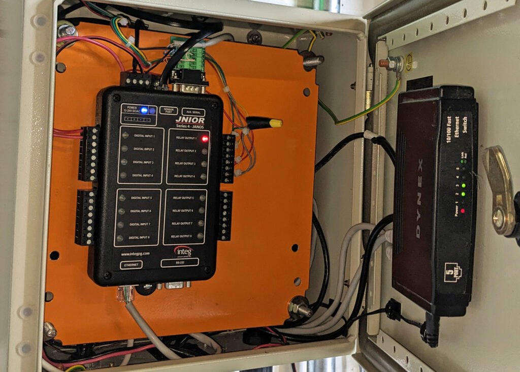
Figure 3: The INTEG JNIOR automation controller is a right-sized platform for combining essential visualization, automation, and connectivity functions, empowering users to enhance solar or other applications with digital capabilities and edge control, without unwanted effort and overhead.
The INTEG JNIOR is an SBC platform optimized for control and monitoring, with on-board I/O, and serial and Ethernet networking connectivity. It includes industry certifications and free support, all at a reasonable one-time cost. The controller features a purpose-built multi-tasking operating system (OS) for responsive control, and it supports edge networking features like TLS/SSL secure SSH, SFTP, Telnet, and FTP, along with a full-featured web server with WebSockets extensions.
An optimized Java Virtual Machine (JVM) empowers users to simply and quickly develop, run, and debug dependable programs, with optional browser-based visualization and control. The combination of a managed OS platform with an open and stable programming environment makes it easy to develop and support reliable functionality. The controller can execute multiple application programs written in Java™, and those programs can be created externally on a PC using free programming tools.
With the controller mounted in an industrial enclosure for environmental protection and wiring convenience, it was time to make the networked and hardwired I/O connections. Once the controller was connected to the site network, it was immediately reachable with a standard browser and served up a default configuration webUI. Hardwired I/O connections included a discrete input from the grid monitor relay, and discrete outputs to operate the stacklight.
Obtaining data from the inverters servicing the ground-mounted arrays was the first real challenge. The controller supports MODBUS server and client applications, and it is supplied with an open-source subroutine that is easily adapted to read values from devices such as the inverters, once the source data structure is known. A program was created to read data from all four inverters is a 15-second repeating loop, so that instantaneous information (including voltages, currents, and more), and also daily and overall totals, could be retrieved and stored into the controller registry, where it became available for viewing via the web interface.
The controller includes a real-time clock so that operations can be scheduled as needed, and a built-in network sniffer aids with communications commissioning. Once these communications were proven out, a similar approach was applied to connect with the two power meters over an RS-485 serial connection.
Another simple Java program tracks the status of the grid monitor relays and uses power flow information, summing the instantaneous power supplied by each inverter and the battery backup system, and subtracting the facility load to obtain amount of power being supplied by or fed to the grid. This routine provides information for the web interface, and it operates the stacklight and beeper as needed. Because I/O handling proved so easy, inputs were added for tracking temperature and humidity.
Because the battery backup system did not offer an appropriate communications option, it was not possible to obtain the actual state-of-charge information. However, a model was derived to estimate the charge based on solar power provided to the batteries and power output of the system, modified with an efficiency estimate. This model proved sufficient to indicate the battery status.
A second JNIOR controller was set up elsewhere at the facility, mirroring the main controller’s I/O, to provide the outputs needed for another stacklight station. Once the basic functionality and data collection was in place, a Linux based server was added to collect the data from the JNIOR and store it long term in an open-source MySQL database, which in turn can supply much more elaborate web pages with active power plots. Eventually, the plan is to use this second controller to implement energy saving steps, such as minimizing air conditioning usage, for prolonging battery runtime if there is a utility failure.
36KW Ground Mounted Array
The ground mounted system is preferred because it not only allows the array to be optimally positioned and more easily serviced, it allows the panels to run cooler and therefore more efficiently; This avoids the issue with maintaining or replacing the roof on the residence; And, it also does not put the home at risk due to fire resulting from any fault of the high powered electrical systems involved.
Panels are fixed at a 30-degree angle and aimed due South. While additional power may be gained by tracking the Sun, any mechanical movement would involve additional hardware and present an ongoing maintenance concern. If more power is desired the preferred solution is to add more panels. If anything could be done to improve performance it would be to add some form of passive cooling. The lower the temperature the more efficient the panels become and the more power will be generated.
This system uses 100 Heliene 360W panels connected to 4 SMA SunnyBoy 7.7-US-41 grid connected inverters. An application runs on the JNIOR that polls these four inverters every 10 seconds using MODBUS. This collects instantaneous power levels as well as daily and lifetime totals. Additional information such as the line voltage of each phase is included. The data is simply written to the Registry where it can be easily monitored via the WebUI and shared with the other programs in the system.
10KW Tesla PowerWall System
This system deploys 10KW of roof-mounted panels. While not considered ideal the barn roof presented as an obvious location for these panels. Concerns regarding roof maintenance are minimal given that the roofing had been replaced earlier in the installation year. Roofing issues themselves are less of a concern given that this is located on a BARN. And, because it is a barn the risk of fire from electrical malfunction (arc faults) is a bit less concerning.
A Tesla PW+ and two Tesla PW2 couple to provide 42 kWh of backup battery power and 100A of electrical service for the home. When fully charged this system can operate the home off-grid for two days in the absence of solar charging. Potentially, even when solar conditions are poor, this system could maintain off-grid operation for very long periods of time. Air-conditioning consumes a significant amount of power. If it should become necessary to run off-grid and in the absence of utility power for any lengthy duration, the air-conditioning could turned off.
The PowerWall is configured to run in self-powered mode from 6PM until 9AM. That is to say that from dusk to dawn the system is allowed to power the home from the batteries. This then minimizes the purchase of power from the utility. During the day when solar is active the system serves only as backup and is instructed to focus on battery charging. Once fully charged any excess solar energy is exported to the grid. During this time the ground mounted array is also exporting. The net effect is that generally the property only exports power.
Tesla severely limits that ability to acquire information from their systems. The user is referred to a cell-phone app for that. Since we are interested in automating the data collection additional power meters were installed around the PW system. These are read on the 10 second interval by another JNIOR application that communications over RS-485. Power readings are collected and added to the Registry section along with the ground mount solar status.
Reporting
Periodically a local Ubuntu server makes an Ajax-style request to the monitoring JNIOR. A simple PHP script returns the Registry section in JSON. That is parsed and the data is stored in a MySQL database. A WebServer on that machine provides a real-time status. This is publicly available at https://cloutieronline.net.
Here the performance of the system can be monitored. This then is utilized to affect how power is used in the home in support of conservation but also to insure that power is available even though a lengthy grid outage.
Sunny days ahead
Obtaining and installing the solar panels, inverters, and batteries represents a large cost. Once in production, only a small fraction of the solar power generated at this site is consumed by the facility. This reduces the monthly electric bill to $0.00 and actually creates a revenue stream, offsetting other expenses.
The ability to implement a streamlined SCADA platform using familiar and open configuration methods has provided a useful operational view at a low initial cost, and with no further recurring costs. A wealth of data is available to support optimization efforts, helping the end user get the most from their investments.
Contact INTEG support with any questions. We will be happy to share any and all details of the application.