The Edge Controller Turns 25
Summary: Twenty-five years ago, an industrial controller connected real-world I/O to Ethernet, TCP/IP, Java applications, Web browsers, and remote systems. We still have the original hardware and documentation. So we opened one up to see exactly what was inside.
At the beginning of this century, the industrial world was already well into a transition. [1] Ethernet and TCP/IP had become established technologies, the Web was rapidly changing how information could be accessed, and Java promised a portable application environment. Meanwhile, industrial control still depended on the very real world of digital and analog signals, relays, sensors, serial communications, and equipment expected to operate reliably for years. Bringing these two worlds together presented an interesting engineering problem.
The terminology we use today had not yet arrived. No one at INTEG was talking about edge controllers, edge computing, or OT–IT convergence in 2001. Those are terms we might apply looking back from 2026. For now, we are going to look at what was actually built—both hardware and software—and how it connected the physical world of industrial control with the emerging information technologies of the day. Then you can decide what to call it.
>> The Product of Interest
The device we are going to examine is the JNIOR-A (P/N JNR-100-000A), released August 21, 2001. It is a compact embedded controller built around a networked Java computing platform and surrounded by the circuitry needed to interface with real-world equipment. We have the original hardware, schematics, bill of materials, and contemporary software design documentation, so there is little need to speculate about how it worked.
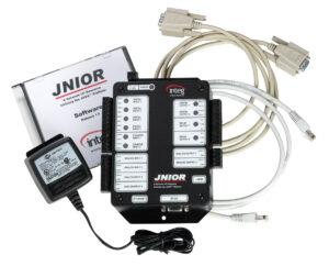
The original JNIOR-A with power supply, Ethernet, serial cabling, and software.
A molded UL-rated housing protects the electronics while leaving field wiring accessible around the perimeter through screw-terminal connections. Ethernet and RS-232 have dedicated connectors, while indicators visible through the front panel provide immediate status for the various inputs and outputs. The result is a self-contained controller intended for installation alongside industrial equipment, rather than a circuit board requiring the customer to provide packaging and interconnection.
The enclosure itself is not intended to provide protection from moisture, dust, or other harsh environmental conditions. Those applications would place the controller within an appropriate NEMA-rated enclosure. Within the protected environment of a typical control cabinet, however, the JNIOR-A provides the packaging, connections, and visual feedback needed for installation as a finished piece of equipment.
Power enters through the same style of field connector. The JNIOR-A accepts 7–30 VAC or DC, with the input circuitry eliminating concern over polarity when DC power is used.
Let’s take the cover off.
>> Under the Hood
Removing the cover reveals that the controller is built around two distinct pieces of hardware. At its center is a Dallas Semiconductor TINI computing module. Surrounding it is the INTEG-designed circuitry that connects that computer to the physical world.
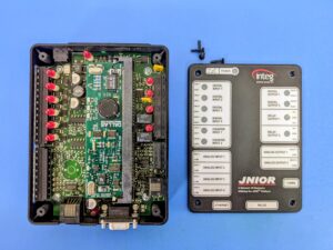
With the cover removed, the Dallas Semiconductor TINI computing module occupies the center of the JNIOR-A motherboard, surrounded by the circuitry connecting it to the physical world.
Much of the perimeter of the board is devoted to removable two-part terminal connectors. Field wiring can remain attached to the connector while the controller is removed or replaced. The available I/O includes four isolated digital inputs, two counter inputs, four analog inputs, two digital outputs, two Form-C relay outputs, and two analog outputs. LEDs associated with the digital I/O provide immediate indication of input and output states.
Along one edge is an RS-232 serial port. For an application, this provides a straightforward way to communicate with equipment that relied on serial communications. It also provides access to the command-line interface before Ethernet has even been configured. A new controller can therefore be powered, connected locally through a terminal, and brought onto the network without first requiring network access.
Moving inward from the field connections, the most prominent feature is the daughterboard mounted near the center of the controller. It plugs into the JNIOR-A motherboard through what looks remarkably like a familiar memory-module connector. This is the TINI computing platform supplied by Dallas Semiconductor, containing the processor, memory and much of the networking infrastructure on which the controller is built.
Before looking more closely at TINI, we can remove the module and get an unobstructed view of the JNIOR-A motherboard underneath.
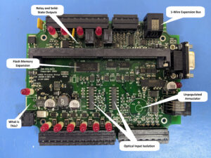
The JNIOR-A motherboard with the TINI computing module removed.
The digital inputs are optically isolated, keeping field signals electrically separated from the controller electronics. On the output side, electromechanical relays provide isolated dry-contact switching for equipment that cannot—or should not—share the controller’s electrical reference. Other circuitry handles the analog inputs and outputs, counters, digital outputs, serial communications, and power conditioning.
Taken together, this circuitry provides the interface between two very different environments. On one side are field voltages, sensors, contacts and equipment. On the other are the logic-level signals expected by a computer.
That computer sits on the removable module at the center of the board. Let’s take a closer look.
>> The Computer at the Core
At the core of the JNIOR-A is a Dallas Semiconductor DSTINI1-1MG TINI module. In modern terms, this is essentially a single-board computer packaged in the form of a 72-pin memory module. It contains everything needed to compute: a Dallas DS80C390 microprocessor, static RAM, Flash program memory, a real-time clock, an Ethernet interface, and the supporting circuitry needed to operate as a networked computer.
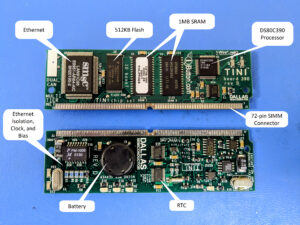
The Dallas TINI processing module combined the processor, memory, Ethernet interface, real-time clock, and battery-backed SRAM on a 72-pin SIMM-format daughter board.
The module plugs into the JNIOR-A motherboard through its 72-pin SIMM-style connector, which also brings the processor bus out to the surrounding circuitry. The JNIOR-A motherboard adds additional Flash program storage, but the computer itself is substantially contained on this removable module. The result is a complete embedded computing and networking platform in a remarkably compact form.
One particularly nice mechanical detail is the small black cover protecting the real-time clock battery. Pop the cover off, however, and there is a design choice that looks less attractive 25 years later. The CR1632 lithium coin cell is soldered directly to the board rather than installed in a replaceable holder.
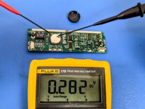
The original 3 V CR1632 battery measures just 0.282 V during our 2026 teardown.
The battery maintains the static RAM when power is removed, and that memory is important to the TINI software environment. The manufacturer-supplied firmware implements a Java Virtual Machine and the Slush command shell, with the latter relying on battery-backed SRAM for persistent storage.
Twenty-five years later, this particular 3 V CR1632 battery measures below 0.3 V. In our experience, batteries of this type typically provide about six to eight years of service. Replacing a consumable battery with a soldering iron is not a feature we would design into a product intended for a long service life.
The DS80C390 is an enhanced member of the long-lived 8051 microcontroller family. Operating at up to 40 MHz, it extends that architecture with a 24-bit address space capable of directly addressing as much as 4 MB of program and data memory. The result is considerably more address space than found in a conventional 8051-based embedded system.
The DSTINI1-1MG module provides 1 MB of static RAM, implemented as two 512 KB devices, together with 512 KB of Flash program memory. The JNIOR-A motherboard adds further Flash program storage through the processor bus exposed at the module connector. These are modest resources by today’s standards.
We have the hardware. Now let’s see how it becomes a controller.
>> Connecting to the Information World
The hardware provides the resources. The firmware determines what the JNIOR-A actually does with them. [2] Let’s power it up and see what we find.
The original JNIOR-A User’s Manual offers a remarkably straightforward definition of the product. [3] It described JNIOR as a “self-contained, general-purpose I/O box” communicating over TCP/IP using Ethernet and capable of being remotely controlled and monitored through a standard Web browser.
The manual goes on to describe applications including remotely monitoring equipment status and process signals, interfacing with legacy systems, Web-enabling existing devices, linking I/O with operator interfaces, and sending e-mail alerts.
First and foremost, the JNIOR-A operates as a remote I/O resource. Its digital and analog inputs make information from equipment available to other systems through the network, while its digital, relay, and analog outputs allow those systems to control equipment in return. The firmware provides the means for a remote application to discover the state of that I/O, detect changes, and command outputs.
The JNIOR-A therefore sits between the physical equipment and whatever system needs to interact with it. In a control application, a remote system can read equipment state and command outputs through the JNIOR-A. In a monitoring application, operating conditions, process values, and equipment status travel in the other direction to systems interested in the information.
>> Following a Control Command
Selecting the right mix of I/O has always been a problem for general-purpose control equipment. One application needs more digital inputs, another needs analog signals, and another needs additional outputs. Modular control systems address the problem by allowing the required I/O to be assembled for each installation. As a self-contained product, the JNIOR-A provides a little of everything: digital and counter inputs, analog inputs and outputs, and two different forms of digital output.
The two types of digital output are quite different. Two are solid-state outputs suitable for directly switching DC loads, while two Form-C relay outputs provide isolated dry contacts for equipment requiring a conventional contact closure. A remote system can command either type through the same network-connected I/O resource.
To control the JNIOR-A from another system, an application first establishes a persistent TCP connection to the controller and communicates using the JNIOR Protocol. Clearly defined messages allow the application to read I/O, command outputs, and receive status changes across that connection without exposing the electronics behind the terminals.
Suppose a remote system needs to change the state of one of the relay outputs. It constructs the appropriate JNIOR Protocol command message, identifying the requested action, and transmits that packet across the open TCP connection to the JNIOR-A.
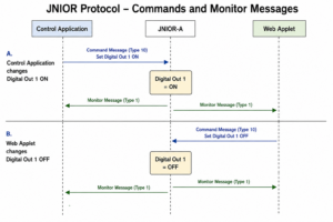
JNIOR Protocol clients remain synchronized as I/O changes, regardless of which connected client initiates the change.
Once received, the JNIOR-A firmware decodes the command and translates the requested action into control of the appropriate hardware output. In our example, that means driving the circuitry associated with the selected relay, causing the physical contact to open or close. What began as a decision made by software somewhere on the network has now crossed the boundary into the physical world and produced an electrical action at the controller’s terminals.
That change in output state also becomes an event. The JNIOR-A updates its internal view of the I/O and sends a Monitor Message over the existing protocol connection reporting the new state. The remote application does not have to poll the controller to determine whether something has changed; the JNIOR-A reports the change when it occurs. The same connection that carried the command toward the physical equipment therefore carries the resulting status information back toward the system that issued it.
The application holding the network connection is not necessarily the only thing capable of changing an output. Someone could also toggle the relay through the JNIOR-A Web interface. The resulting Monitor Message is sent to connected clients, allowing each to learn the new state regardless of which one initiated the change.
>> Monitoring the Physical World
The same mechanism works when no control action is required. Changes at the JNIOR-A inputs originate in the physical world rather than somewhere on the network. When a digital input changes state, for example, the firmware detects the event and reports the new condition through a Monitor Message to connected applications.
This makes monitoring essentially the reverse of the control path we just followed. A sensor, contact, or other field signal changes at the JNIOR-A terminals, the hardware conditions and isolates that signal, the firmware recognizes the new state, and the information is delivered across the network to whatever system needs it.
Looking a little deeper, we find that the JNIOR-A does more than report whether an input is on or off. A pair of digital inputs include counters, allowing the controller to accumulate transitions locally. Input counts can also be compared against configured alarm levels, providing another piece of information that can be reported to the remote system.
The firmware also maintains usage information for the I/O, accumulating the amount of time that inputs and outputs remain active. An internal temperature sensor provides another locally available operating measurement.
The counting and metering take place within the JNIOR-A itself. A remote computer or network connection may not be available when an event occurs, but the JNIOR-A continues accumulating counts and usage locally.
There is no power switch. Interestingly, the motherboard provides a connection for SW1, but the production unit has that connection jumpered. The JNIOR-A is installed, powered, and left operating continuously—24 hours a day, 7 days a week, 365 days a year.
>> Open the Web Browser
Enter the JNIOR-A’s IP address into a Web browser and another side of the product appears. The controller serves its own Web pages, providing access to configuration along with a Monitor and Control interface showing the current state of its I/O. Digital inputs and outputs can be viewed directly, counters and other operating information are displayed, and—with the appropriate access—a relay output can even be toggled from the browser.
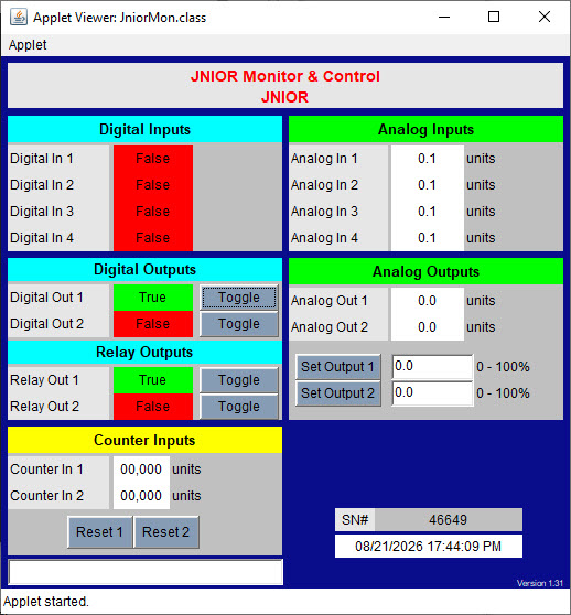
The original JNIOR-A Monitor & Control applet, running during our 2026 teardown.
The live status is possible because the browser interface is not working from a static snapshot of the controller. The Java applet establishes its own connection to the JNIOR-A and uses the same underlying JNIOR Protocol to receive changes as they occur. When an input changes or an output is commanded elsewhere, the information can therefore appear at the browser without requiring the user to continually refresh the page.
The Web interface also makes the JNIOR-A useful right out of the box. No supervisory system has to be programmed and no custom application has to be written before the controller can be installed, configured and put to work. Connect it to the network, open a browser, and the available I/O can immediately be viewed and controlled.
A larger control or monitoring system can integrate the JNIOR-A through the JNIOR Protocol, but the controller does not depend upon that system for its basic usefulness. Installation, configuration, testing, and troubleshooting can all take place locally at the equipment or remotely across the network using tools already available on an ordinary computer.
Information that once existed only as voltages, contact closures, and indicator lights inside a control cabinet can now be viewed from any computer with network access to the JNIOR-A. The technician standing beside the equipment can see it—but so can the engineer in another room, the operator elsewhere in the plant, or, for that matter, the boss upstairs.
The browser interface also provides access to configuration. Network settings, I/O parameters, alarm thresholds, and other operating values can be changed without opening the enclosure or connecting a programming device to the controller.
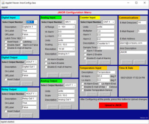
The original JNIOR-A Configuration applet running during our 2026 teardown.
The browser, however, is not the only way into the controller. The JNIOR-A also provides command-line access through Telnet, along with FTP for transferring files. The same command-line interface is available through the RS-232 port, providing a local administrative path even before network communications have been established. Once connected to the network, those administrative capabilities become available remotely.
After the wiring is complete, configuration can be examined, operating conditions can be checked, files can be transferred, and the controller can be administered from elsewhere on the network without another trip to the control cabinet.
Files transferred through FTP can include application software. Even the operating software itself can be updated remotely.
>> The Architecture That Emerges
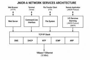
Stepping back from the individual features, a fairly clear architecture emerges. At one boundary, the JNIOR-A connects directly to physical equipment through isolated digital signals, relays, counters, analog signals, and serial communications. At the other, it connects to the information world through Ethernet and TCP/IP. Between those two boundaries is a continuously operating embedded computer responsible for interpreting, accumulating, and communicating information in both directions.
That computer does more than translate one interface into another. It maintains state, counts events, meters usage, and evaluates alarms close to the equipment. It can report changes to remote systems as they occur, while accepting commands that produce actions back in the physical world. Those remote systems need not remain continuously available for the JNIOR-A to continue observing what is happening locally.
At the same time, the network connection serves people as well as machines. A Web browser provides immediate visibility and control without requiring a larger system to be developed first. Configuration and administration are available remotely, files and application software can be transferred across the network, and even the operating software can be updated without visiting the installed controller.
What emerges is a collection of responsibilities gathered together in one small, purpose-built industrial device. The JNIOR-A sits immediately beside the equipment, yet makes that equipment accessible to applications and people elsewhere on the network.
>> Twenty-Five Years Later
Looking at the JNIOR-A through today’s terminology, much of what we have examined sounds familiar. We would talk about OT–IT integration, local processing, event-driven communications, remote management, and making operational information available to systems beyond the control equipment itself. Those terms came later. The architecture we have just examined shipped on August 21, 2001.
Twenty-five years also gives us something else to examine: longevity. Equipment installed alongside machinery is expected to remain useful for years, often decades. Networks change, security requirements evolve, software environments disappear, and new ways of integrating systems become necessary.
The JNIOR-A was the beginning of that evolution. The hardware and software have changed substantially over the succeeding 25 years, while the basic job of connecting real-world equipment to networked systems has remained. Today’s Series 4 JNIOR bears little resemblance internally to the controller we just opened, yet continues that same role.
Perhaps that suggests another under-the-hood examination. Twenty-five years later, what would we find if we opened a current Series 4 JNIOR and followed the same paths through its hardware and software? Much of the architecture would look remarkably familiar—a testament to the longevity of the original design. But we would also find capabilities that are unexpected.
What we found in the JNIOR-A is a purpose-built industrial controller positioned at the equipment, connecting physical I/O with networked systems, performing useful work locally, communicating in both directions, and making operational information available to people and applications elsewhere on the network. We began by leaving the terminology to the reader. Twenty-five years later, doesn’t that architecture fit rather neatly into a modern classification?
>>
References
- INTEG Process Group, Inc., Java Based Distributed Computing for Real-Time Embedded Systems, Navy SBIR Proposal N011-0978, January 8, 2001.
- INTEG Process Group, Inc., JNIOR Software Description, Rev. 0.1, May 24, 2001.
- INTEG process group, inc., JNIOR User’s Manual, Release 1.4, 2003.
JNIOR At Work in 2026