JNIOR USERS MANUAL
JANOS Help System
19 Dec 2025

Website :
integpg.com
JANOS Version : v2.5.3-b8
Help Revision : 19 Dec 2025 10:01
Includes : FtpClient, JBakup
JANOS - JNIOR Automation Network Operating System
Copyright (C) 2012-2026 INTEG Process Group, Gibsonia PA USA
TABLE OF CONTENTS
Product Overview ........................................................ 1
Formalities ............................................................. 6
Trademarks ......................................................
6
Licensing .......................................................
7
Limited Warranty ................................................
8
Getting Help ........................................................... 11
Help System (HELP) .............................................
11
Technical Support ..............................................
13
Getting Started ........................................................ 14
Power UP .......................................................
14
User Interface .................................................
14
Network Access .........................................
14
Command Line Interface (CLI) ...........................
16
Secure Shell (SSH) .....................................
16
Serial Access ..........................................
18
Networking Basics ..............................................
19
IP Settings ............................................
20
Time Synchronization (NTP) .............................
23
Factory Configuration ..........................................
23
Firmware ...............................................
23
Files ..................................................
24
Factory Reset ..........................................
27
Security ............................................................... 28
Default Accounts ...............................................
28
Limit Connectivity .............................................
30
Secure Communications ..........................................
31
Cyber Defenses .................................................
33
Greylisting ............................................
34
Visibility .............................................
35
Blacklisting ...........................................
36
Summary ........................................................
39
User Commands .......................................................... 41
Command Line ...................................................
41
Command History ........................................
41
TAB Auto-Complete Feature ..............................
42
Current Working Directory (CD) .........................
47
Command Line History (HIST) ............................
47
Configuration ..................................................
48
Setting Date and Time (DATE) ...........................
48
Network Addresses (IPCONFIG) ...........................
50
Setting the Hostname (HOSTNAME) ........................
52
Registry Settings (REG) ................................
53
File Management ................................................
55
Listing Files (DIR/LS/FIND) ............................
55
Removing Files (RM) ....................................
57
Copying Files (CP) .....................................
58
TABLE OF CONTENTS (cont'd)
Moving Files (MV) ......................................
59
Renaming Files (REN) ...................................
59
Creating a Directory/Folder (MD) .......................
60
Removing a Directory/Folder (RD) .......................
61
Library Manager (ARC/JAR/ZIP) ..........................
61
Modifying Permissions (CHMOD) ..........................
63
Changing Ownership (CHOWN) .............................
64
Command Line Tools .............................................
65
Displaying Text Files (CAT/TYPE/HEAD/TAIL) .............
65
Searching File Content (GREP/EGREP) ....................
67
Locally Editing Text Files (EDIT/ED) ...................
69
Issuing an Email (SENDMAIL) ............................
75
Making a Log Entry (LOGGER) ............................
76
Accessing Peers (TELNET) ...............................
77
Update File Timestamp (TOUCH) ..........................
77
Batch Scripting and Program Execution ..........................
78
Executing an Application (JAVA) ........................
78
Executing Scripts and Batch files (RUN/EXEC) ...........
79
Process Environment (SET) ..............................
81
Batch Mode Text Display (ECHO) .........................
82
Process Management .............................................
82
Displaying Activity (PS) ...............................
82
Detailed Application Status (THD) ......................
83
Stopping an Application (KILL/STOP) ....................
84
Restarting an Application (RESTART) ....................
86
JNIOR Digital and Analog I/O ...................................
89
Managing External Modules (EXTERN) .....................
89
Logging (IOLOG) ........................................
90
Locally Controlling I/O (JRMON) ........................
91
User Accounts ..................................................
94
Listing Users (USERS) ..................................
94
Setting Passwords (PASSWD) .............................
95
Modifying Permissions (USERMOD) ........................
95
Adding Accounts (USERADD) ..............................
96
Removing Accounts (USERDEL) ............................
97
Displaying User Groups (GROUPS) ........................
97
Adding a User Group (GROUPADD) .........................
97
Removing a User Group (GROUPDEL) .......................
98
Modifying a User Group (CHGRP) .........................
98
Network Utilities ..............................................
99
Network Status/Packet Capture (NETSTAT) ................
99
SSL/TLS Certificates (CERTMGR) ........................
104
Testing Connectivity ..........................................
106
System Maintenance ............................................
109
Rebooting (REBOOT) ....................................
109
System Statistics (STATS) .............................
109
File Monitoring (MANIFEST) ............................
110
Performing Updates (JRUPDATE) .........................
112
Registry .............................................................. 115
System Configuration .................................................. 116
TABLE OF CONTENTS (cont'd)
Built-in Dynamic Keys .........................................
116
Device Keys (Device/) .........................................
118
Network Configuration ................................................. 119
Secure Communications Using SSL/TLS ................................... 137
Basic Authentication ..........................................
137
RSA Keys ......................................................
140
SSL Certificates ..............................................
141
Event Management ...................................................... 146
Startup Events (Events/OnBoot) ................................
146
Alarm Events (Events/OnAlarm) .................................
148
Email Configuration ................................................... 151
Custom Email Notifications ....................................
151
General Settings ..............................................
154
Server Configuration .................................................. 157
World Wide Web (Web) Server ...................................
157
Websocket Interface ...........................................
161
JANOS Management Protocol (JMP) ...............................
163
JNIOR Protocol (Deprecated) ...................................
164
File Transfer Protocol (FTP) ..................................
167
Telnet Server - Console Access ................................
168
Secure Shell (SSH) Server - Console Access ....................
169
BEACON Protocol Service .......................................
169
Input/Output (I/O) Configuration ...................................... 171
Digital Inputs (DIN) ..........................................
171
Configuration by Input (IO/Inputs/[DIN]/) .....................
176
Relay Outputs (ROUT) ..........................................
187
Configuration by Output (IO/Outputs/[ROUT]/) ..................
188
Serial RS-232/RS-485 Ports ............................................ 192
AUX Serial Port ...............................................
192
COM RS-232 Port ...............................................
196
ZIP/JAR Compression ................................................... 199
JANOS Management Protocol (JMP) ....................................... 201
Secure Communications .........................................
203
Initial Connection ............................................
204
Messaging .....................................................
205
I/O Monitoring ................................................
207
Control Messages ..............................................
209
File System Commands ..........................................
213
Registry Commands .............................................
220
Console Access ................................................
224
External Devices ..............................................
228
Realtime Clock ................................................
232
Shutdown/Reboot Notification ..................................
233
TABLE OF CONTENTS (cont'd)
System Logging (Syslog) .......................................
233
Auth-Digest Calculation .......................................
235
Application Programming ............................................... 236
Java Virtual Machine (JVM) ....................................
236
Compiling Program Files (JAR) .................................
237
Web Development ....................................................... 238
Scripting (PHP-like) .................................................. 241
Script ........................................................
241
Variables .....................................................
243
Statements ....................................................
246
Expressions ...................................................
248
Functions .....................................................
254
User-Defined ..........................................
254
Built-In ..............................................
256
Rendering & Output ............................
256
String Operations .............................
257
Array Operations ..............................
259
Math Functions ................................
260
Conversions ...................................
262
Date & Time ...................................
263
File System Functions .........................
264
JSON Functions ................................
266
Language Support ..............................
266
Registry Access ...............................
267
System Functions ..............................
267
Regular Expressions (REGEX) ...................
268
Including Files ...............................................
269
Error Handling ................................................
269
Example: Batch Scripting (CKSUMS) .............................
271
Hardware .............................................................. 275
JNIOR Models ..................................................
275
Power Supply ..................................................
275
Relay Outputs .................................................
277
Digital Inputs ................................................
277
COM Serial Port ...............................................
278
AUX Serial Port ...............................................
279
Sensor Port Expansion Bus .....................................
280
Memory Areas ..................................................
281
References ............................................................ 283
Users Manual ..................................................
283
Timezones .....................................................
283
System Logs ...................................................
286
Process Environment ...........................................
287
Network Filtering .............................................
289
SafeMode ......................................................
292
Regular Expressions (REGEX) ...................................
293
Printf Format Specifiers ......................................
294
TABLE OF CONTENTS (cont'd)
ASCII Table ...................................................
297
UTF-8 Encoding ................................................
298
Morse Code ....................................................
298
Javascript Object Notation (JSON) .............................
299
JNIOR Protocol ................................................
300
VT-100 Terminal Compatibility .................................
300
FTP Client Application ................................................ 304
Command Line Syntax ...........................................
304
Interactive Mode Commands .....................................
305
JBakup Log Archiving Application ...................................... 307
INDEX ................................................................. 308
Overview JNIOR
PRODUCT OVERVIEW
JNIOR is general purpose single board computing device designed to flexibly
interact with other devices, collect data, initiate complex actions, and to
support remote users and systems. Unlike the personal computer the JNIOR does
not utilize a screen, keyboard or mouse. It has been developed to be
integrated/embedded into other systems. One uses, maintains and programs
the JNIOR through the network using a web browser or other application. The
product line offers a number of JNIOR models and accessories.
The JNIOR is a highly stable and reliable product. It offers a low cost of
ownership with no intended obsolescence, no need of periodic replacement, and
no ongoing charges. It is ideal for incorporation into any system where you
need confidence that it is fully supported by the company and will be available
for years to come. In fact JNIORs shipped in 2005 (Series 3) are still in
operation today.
Support is both free and frustration-free in that no AI or contract support
people are ever involved. When you need help you are assisted by the actual
product and application developers. There is no need to elevate any issue as
there is no one better suited to address the problem than those helping you.
Your needs can be quickly addressed even if it requires a software/firmware
change.
Uniquely, JNIOR has been completely developed by INTEG and those people remain
directly involved today. The product is produced in our own facility. The
operating system (JANOS) for the Series 4 was developed by a single author and
involves absolutely no third party code or open source ensuring that any
(replicable) issue can be immediately corrected. Even the more complex random
concerns can be eventually hunted down and extinguished. There is just no where
to point fingers. No one else to blame.
The product reflects decades of experience with equipment interfacing, low-level
network communication protocols, monitoring and automation. As a result there
are numerous diagnostic capabilities built into the system providing the tools
you need to maintain the performance of any application. These include a
network sniffer (see
NETSTAT), I/O log, serial transmission logs, performance
monitors and more.
The JNIOR is a technologically advanced tool, an inexpensive Programmable Logic
Controller (PLC), that can be easily configured and optionally programmed by
the user to handle automation, control and data collection tasks. The product
has the capacity to handle multiple simultaneous tasks efficiently and to serve
custom websites robustly through its full-featured webserver. The JNIOR has
found a wide range of uses in locations all across the globe.
FUNCTION
The Series 4 JNIOR utilizes a single 32-bit microprocessor supported by a
variety of memory components creating an ideal environment for a general purpose
operating system. The JANOS operating system was developed to be optimized
for such a device and to be as consistent as possible with the earlier
Series 3 product.
Page 1
There are various input and output (I/O) capabilities. Each JNIOR supports
4 to 12 low voltage signal
relays (1A/30V). These are available to make or
break external logic circuits as might be needed to cause action. Similarly
there are from 4 to 12 digital
inputs that generally accept a low voltage
to indicate either an ON or OFF state. These inputs can be used to status the
world around the JNIOR and each supports counting and metering capabilities.
Each JNIOR has 2 serial channels. These can be used to communicate with
other devices and systems. You might transmit a command to prompt another
device (such as a projector) into action. Or you might request/receive
information that can be passed on to other systems or used to trigger some
programmed action. One serial port (RS-232
COM) provides terminal access
to the JANOS command line. The command line is the heart of any operating
system.
Importantly the JNIOR has a 10/100 Mbit Ethernet LAN port. The product supports
a complete TCP/IP stack and is thereby accessible from the local network as
well as through the Internet if desired. JANOS supports a range of protocols
such as HTTP, HTTPS, FTP, SSH, and Telnet including the JNIOR Protocol and
the JANOS Management Protocol (JMP). INTEG supplies the Support Tool which
is an application for the PC that can greatly assist in the management of
any number of JNIORs at any one site.
And finally there is the Sensor Port or Expansion Bus that allows the JNIOR to
communicate with a number of external modules. Those accessories can provide
additional relays (10A/220VAC), 10V analog signals, and 4-20ma current loop.
There is also a 3-channel LED dimmer and a rack mounted switch panel with
indicators.
UNPACKING
The JNIOR is sold in quantity to integrators and system providers. It is not
sold in retail outlets. It is therefore not packaged in typical retail form.
The JNIOR is quite literally a
Black Box given that its enclosure is black
but also as according to the
Oxford Dictionary it is a "complex piece of
equipment, a unit in an electronic system, with contents that are mysterious
to the user". This book hopes to eliminate the mystery.
Each JNIOR should be accompanied by 5 screw-terminal connectors (1 4-pin and
4 8-pin) providing connection to the various I/O and power ports. These are
typically shipped in a separate bag. Care should taken to not lose those and
to keep them with each JNIOR.
The standard supply available from INTEG is 12VDC at 1A. As these units may
be incorporated in larger systems customers are allowed to provide their own
source of power. We recommend that the power source be capable of supplying
at least 1A to each JNIOR. The voltage may also vary in the range from 10V
to 24V. The 410, 412 and 414 models can be alternatively powered by an AC
voltage.
When powered a blue LED will be illuminated on the Series 4. A green power
LED was used on the Series 3.
Page 2
OS CAPABILITIES
When power is applied the JANOS operating system boots. The boot procedure
initializes and starts the various background services required by the
product.
Multi-Tasking
JANOS is a preemptive multi-tasking system. It can run up to 16 individual
programs simultaneously. The boot process completes and becomes the
Idle
process. This is where the product spends its time when it has nothing to do.
A
System process is created to perform background tasks as might be needed
from time to time. And JANOS also creates a
Network process which gives
priority attention to the network and any communications that may be necessary.
Processes are created and terminated as required. For instance when a browser
opens a webpage on the JNIOR the
WebServer process is started. The JANOS
Web Server can handle multiple simultaneous connections from any number of
users and client systems. This one process works to service all of the
transactions required. The process is terminated after a few minutes without
a connection.
Applications provided by INTEG, or written by the customer, are created using
Java. JANOS can execute Java programs directly out of the JAR files created by
the Java compiler. These must be built against the JanosClasses.jar runtime
library. Applications may be started automatically at boot or run as needed
from the command line. Application programs can be written to perform
automation tasks, collect data, perform maintenance tasks, augment the set of
user commands or even implement a network server and custom protocol.
A command line connection or
Console Session is handled in its own process.
Multiple console sessions may be opened simultaneously since JANOS can
support multiple simultaneous logins. Up to 32 users can be defined and
given various permissions. Typically you only need the one main administrator
account.
Applications
Application programs are available from INTEG and can be easily developed by
users with available free interactive development environments (IDEs) like
Netbeans. In order to maintain stable and reliable performance, in the face
of software obtained potentially from many sources, a
managed language is
used. A managed language basically is one that generally handles all access
to memory for the programmer limiting the chance of error that might cause a
system breakdown. For instance there is no method by which a random memory
location, one that is used by other system activities, can be accessed by
an application. No
pointers as there are in the C language. JANOS uses the
Java programming language.
Java is a compiled language. Programs written in Java are compiled by the IDE
into library files with the JAR extension. Note that a
JAR file is the same
format as a
ZIP file. Tools for the latter can be used to examine the former.
The compiled program files contain
bytecode in the form of
classes which
are loaded and executed by the operating system when called upon to do so.
Page 3
JANOS supports its own Java Virtual Machine (JVM). Each application runs in
its own process with its own instance of the JVM. From the command line you
can view the processes using the
PS command. Use the -V option for details.
Networking
The JNIOR supports a Local Area Network (LAN) connection and JANOS contains
a full-featured
network stack. The operating system can receive and send
packets (UDP) as the various services may require. This also supports incoming
and outgoing TCP/IP
connections. The OS and applications can configure the
network to listen for incoming traffic and process outgoing exchanges as
needed.
Security is critical these days. The JNIOR is challenged in that the industry
continues to strengthen the levels of required security and this becomes more
and more computationally expensive (i.e. slow to calculate). The Series 4 does
support TLSv1.2 and can establish encrypted channels. These are
secure even
though a browser might complain given that the
certificates supplied by the
JNIOR have not been
signed by a paid-for authority. JNIOR supports HTTPS
web access.
WEBSERVER CAPABILITIES
The Web Server supports both user authentication and public page services.
Both plain text and TLSv1.2 secure (encrypted) communications are possible.
The JNIOR is supplied with a default WebUI providing for configuration and
status of the product.
You can create your own custom websites to replace the default WebUI. The
WebUI would then be accessible through the /config subfolder. JANOS supports
a PHP-like server-side scripting language (compiled) for dynamically rendering
web pages. Websites rendered by server-side scripting that utilize JavaScript
can create a very powerful user experience. The WebUI is an example. Code
can be extracted from the ZIP file and reviewed for reference.
JANOS uniquely can serve an entire website out of a single ZIP library file.
The WebUI. for example, is distributed in the
/flash/www/config.zip file
which is not ever expanded. Each individual file required by the website is
read from the ZIP library as needed. This means that all of the files associated
with, and required by, a website implementation are kept together in a single
library file. This affords a level of source control ensuring that all of the
files for a particular website are of the correct version and never become
missing or fall out of sync.
The webserver supports
Websockets. This allows a standard web connection to
be
elevated beyond the HTTP protocol supporting a more general binary
exchange. JANOS by default offers the
JMP Protocol through this capability.
An application can be written to handle other protocols through Websockets.
The JNIOR can be completely managed through a web connection. External access
to the standard ports (80/443) is all that is needed. The supplied WebUI
relies upon and completely demonstrates this.
The capabilities of the JANOS WebServer are sufficiently robust that the JNIOR
has found use in network-facing applications in which the built-in digital I/O
are secondary.
Page 4
THE BOOK OF JANOS
JANOS includes a
HELP system which is both accessible from the WebUI and the
command line. This text therefore requires minimal formatting so it can be
displayed in textual form at the command line. The content is contained in
the
/flash/manpages.zip file written in a document styling language. The
MAN command is an alias for HELP.
HELP content is broken down into
Categories and
Topics. There are hundreds
of individual topics and the system includes a
search facility to assist in
locating the information that you are seeking.
From the WebUI you can generate a
printable manual which renders all of the
HELP content in book form including a Table of Contents and Index. All of
this with functional links which can be saved/printed to a PDF for general
reference. Applications loaded on your JNIOR can supply additional help
detail which will be included in this manual. Each manual is customized to
configuration of its source JNIOR.
The Book of JANOS available from INTEG contains this users manual content
and includes a faux leather cover with this title. While the physical book
may be a novelty it does come in handy. It also adds considerable value to
any bookshelf.
SUMMARY
The Series 4 JNIOR running JANOS is highly capable and can be applied in a
very wide variety of situations. This was designed to be generic and not
developed specifically for any one market. In contrast application programs
have been created and are supplied at no charge some of which create the product
environment for a specific market (such as digital cinema).
There is additional information, and an online store, on the INTEG website
located at
integpg.com or
jnior.com.
SEE ALSO
HELP Topics:
JMPConnect,
websocket,
JProtocol,
Java,
Compiling
Page 5
Trademarks Legal
JNIOR
JNIOR(R) is a Registered Trademark of INTEG Process Group, Inc. This acronym
stands for the Java Network I/O Resource and is pronounced "Junior". The
JNIOR is the heart of INTEG Automation and has been available in various models
since 2005.
JANOS
JANOS(R) is a Registered Trademark of INTEG Process Group, Inc. This acronym
stands for the JNIOR Automation Network Operating System and is pronounced
"Jan-Us". JANOS is the INTEG developed real-time operating system first
introduced with the Series 4 JNIOR.
JANOS was named after Janus who in myth is the god of comings and goings,
beginnings and endings, passages, gates, transitions and time. All of these
relating to the role of the JNIOR as a data interface/integrator between
systems, devices and hardware of all forms.
INTEG
INTEG(R) is a Registered Trademark of INTEG Process Group, Inc.
INTEG Process Group (also known as INTEG) is located in Gibsonia, Pennsylvania
USA. The company has been developing, manufacturing and supplying automation
products and software since 1999. These products are in use worldwide in
markets such as Cinema, Energy, Transportation, Manufacturing, Security,
Utilities, and Recreation.
Page 6
Licensing Legal
TERMS OF USE
INTEG grants the end-user or business entity ("Customers") using INTEG products
full license to employ these products as desired provided that the use is
completely legal as per any and all applicable laws and regulations. These
products are not certified for, and therefore not licensed for, use in any
life safety situation wherein the operation of the product could place any
person(s) or animal(s) at risk of injury or death.
FIRMWARE LICENSE
The JANOS operating system ("Firmware") remains the property of INTEG Process
Group. The operating system code and associated runtime libraries (such as
JanosClasses.jar) as well as any future updates are licensed for use only
with INTEG products. INTEG reserves all associated Rights. This Firmware
is proprietary to INTEG and is protected under Copyright law. Reverse
Engineering and any use of any portion of the Firmware in any situation
unrelated to INTEG products is strictly forbidden.
APPLICATIONS
Applications, developed for the JNIOR and generally made available by INTEG
to all Customers, are fully licensed for use with any INTEG product.
Custom applications developed specifically for individual Customers under
paid contract are thereby property of Customers. INTEG will not distribute
such applications directly.
INTEG encourages Customers to develop their own applications and will support
their efforts.
Page 7
JNIOR LIMITED WARRANTY
======================
NOTICE TO USERS
THE JNIOR, A PRODUCT OF INTEG PROCESS GROUP, INC. ("INTEG"), IS A MICROPROCESSOR
CONTROL DEVICE INTENDED TO BE UTILIZED WITH A CUSTOMER'S NETWORK TO MONITOR
AND/OR CONTROL DEVICES AND/OR PROCESSES VIA REMOTE LOCATIONS. IN ORDER TO
PREVENT INJURY TO PERSON OR PROPERTY, IT IS THE SOLE RESPONSIBILITY OF THE
CUSTOMER TO INCORPORATE IN THE CUSTOMER'S SYSTEM, REDUNDANT PROTECTIVE
MECHANISMS AND SAFEGUARDS APPROPRIATE FOR THE RISK INVOLVED. CUSTOMER IS
SOLELY RESPOSIBLE FOR THE PROPER INSTALLATION AND USE OF THE JNIOR.
HARDWARE WARRANTY
The JNIOR product ("product") is warranted by INTEG, to the original purchaser,
to be free of defects in materials and workmanship, under normal use, for a
period of two (2) years from the date of original purchase. If during the
warranty period, the product is proven to be defective, INTEG's sole obligation
under this express warranty shall be, at INTEG's option and expense, to replace
the product or part with a comparable product or part with no charge for parts
and labor, repair the product or part with no charge for parts and labor, or
if neither repair nor replacement is reasonably available, INTEG may, in its
sole discretion, refund to Customer the purchase price paid for the product
or part. Replacement products or parts may be new or reconditioned. INTEG
warrants any replaced or repaired product or part for a period of ninety (90)
days from shipment, or through the end of the original warranty, whichever is
longer. All products or parts that are replaced become the property of INTEG.
INTEG shall not be required to install, or be responsible for the costs
associated with the installation of, the replaced or repaired product or part.
SOFTWARE WARRANTY
INTEG warrants to Customer that the JNIOR software ("software") licensed from
it will perform in substantial conformance to their product specifications for
a period of two (2) years from the date of original purchase from INTEG. Any
software upgrades that may be made available by INTEG shall be available to
Customer via CD, E-Mail, and/or INTEG's website at
integpg.com
with no charge to Customer during the warranty period. The installation of
software upgrades shall not extend the warranty period of two (2) years from
the date of original purchase. INTEG does not provide any warranty for any
custom application software developed by the Customer or any other third-party
application software that is licensed to Customer by the third party. In the
event that the JNIOR software as originally provided to customer, and any
upgrades that may be made available by INTEG, shall fail to perform in
substantial conformance to the product's specifications, then INTEG's
sole obligation with respect to this express warranty shall be to refund the
purchase price paid by Customer for the product. INTEG makes no warranty or
representation that its software will meet Customer's requirements or will
work in combination with any hardware or application software added or
developed by the Customer or provided by third parties, that the operation
of the software will be uninterrupted or error free, or that all defects in
the software will be corrected.
Page 8
THIS INTEG PRODUCT MAY INCLUDE OR BE BUNDLED WITH THIRD PARTY SOFTWARE, THE
USE OF WHICH IS GOVERNED BY A SEPARATE END USER LICENSE AGREEMENT. THIS INTEG
WARRANTY DOES NOT APPLY TO SUCH THIRD PARTY SOFTWARE FOR THE APPLICABLE
WARRANTY. PLEASE REFER TO THE END USER LICENSE AGREEMENT GOVERNING THE USE
OF SUCH SOFTWARE OR THE ACCOMPANYING DOCUMENTATION RELATING TO SUCH SOFTWARE.
OBTAINING WARRANTY SERVICE
Customer must contact INTEG within the applicable warranty period to obtain
warranty service. Dated proof of original purchase from INTEG will be required.
In the United States, INTEG may ship a replacement product or part prior to
receiving the original product or part ("advance exchange"). If advance
exchange is not available, then the repaired product or part will be shipped
as soon as reasonably possible, which will be no later than thirty (30) days
after INTEG receives the original product or part. Repaired or replacement
products will be shipped to Customer at INTEG's expense. INTEG shall not be
required to install, or be responsible for the costs associated with the
installation of, the replaced or repaired product or part.
Products or parts shipped by Customer to INTEG must be sent prepaid and
packaged appropriately for safe shipment, and it is recommended that they be
insured and sent by a method that provides for tracking of the package. When
an advance exchange is provided and Customer fails to return the original
product or part to INTEG within thirty (30) days from the date the replacement
product or part is shipped to Customer, INTEG will charge Customer the
then-current published price of such product or part.
WARRANTIES EXCLUSIVE
IF THIS PRODUCT DOES NOT OPERATE AS WARRANTED ABOVE, CUSTOMER'S SOLE REMEDY
FOR BREACH OF THAT WARRANTY SHALL BE REPLACEMENT OR REPAIR OF THE PRODUCT OR
PART OR REFUND OF THE PURCHASE PRICE PAID, AT INTEG'S OPTION. TO THE FULL
EXTENT ALLOWED BY LAW, THE FOREGOING WARRANTIES AND REMEDIES ARE EXCLUSIVE
AND ARE IN LIEU OF ALL OTHER WARRANTIES, TERMS, OR CONDITIONS, EXPRESS OR
IMPLIED, EITHER IN FACT OR BY OPERATION OF LAW, STATUTORY OR OTHERWISE,
INCLUDING WARRANTIES, TERMS, OR CONDITIONS OF MERCHANTABILITY, FITNESS FOR A
PARTICULAR PURPOSE, SATISFACTORY QUALITY, CORRESPONDENCE WITH DESCRIPTION AND
NON-INFRINGEMENT, ALL OF WHICH ARE EXPRESSLY DISCLAIMED. INTEG NEITHER ASSUMES
NOR AUTHORIZES ANY OTHER PERSON TO ASSUME FOR IT ANY OTHER LIABILITY IN
CONNECTION WITH THE SALE, INSTALLATION, MAINTENANCE OR USE OF ITS PRODUCTS.
INTEG SHALL NOT BE LIABLE UNDER THIS WARRANTY IF ITS TESTING AND EXAMINATION
DISCLOSE THAT THE ALLEGED DEFECT OR MALFUNCTION IN THE PRODUCT DOES NOT EXIST
OR WAS CAUSED BY CUSTOMER'S OR ANY THIRD PERSON'S MISUSE, NEGLECT, IMPROPER
INSTALLATION OR TESTING, UNAUTHORIZED ATTEMPTS TO OPEN, REPAIR, OR MODIFY THE
PRODUCT, OR ANY OTHER CAUSE BEYOND THE RANGE OF THE INTENDED USE, OR BY
ACCIDENT, FIRE, LIGHTNING, POWER CUTS OR OUTAGES, OTHER HAZARDS OR ACTS OF
GOD. THIS WARRANTY DOES NOT COVER PHYSICAL DAMAGE TO THE SURFACE OF THE
PRODUCT. THIS WARRANTY DOES NOT APPLY WHEN THE MALFUNCTION RESULTS FROM THE
USE OF THIS PRODUCT IN CONJUNCTION WITH ACCESSORIES, OTHER PRODUCTS, OR
ANCILLARY OR PERIPHERAL EQUIPMENT AND INTEG DETERMINES THAT THERE IS NO FAULT
WITH THE PRODUCT ITSELF.
Page 9
LIMITATION OF LIABILITY
TO THE FULL EXTENT ALLOWED BY LAW, INTEG ALSO EXCLUDES FOR ITSELF AND ITS
SUPPLIERS ANY LIABILITY, WHETHER BASED IN CONTRACT OR TORT (INCLUDING
NEGLIGENCE), FOR INCIDENTAL, CONSEQUENTIAL, INDIRECT, SPECIAL, OR PUNITIVE
DAMAGES OF ANY KIND, OR FOR LOSS OF REVENUE OR PROFITS, LOSS OF BUSINESS,
LOSS OF INFORMATION OR DATA, OR OTHER FINANCIAL LOSS ARISING OUT OF OR IN
CONNECTION WITH THE SALE, INSTALLATION, MAINTENANCE, USE, PERFORMANCE,
FAILURE OR INTERRUPTION OF THIS PRODUCT, EVEN IF INTEG HAS BEEN ADVISED OF
THE POSSIBILITY OF SUCH DAMAGES, AND LIMITS ITS LIABILITY TO REPLACEMENT,
REPAIR, OR REFUND OF THE PURCHASE PRICE PAID, AT INTEG'S OPTION. THIS
DISCLAIMER OF LIABILITY FOR DAMAGES WILL NOT BE AFFECTED IF ANY REMEDY
PROVIDED HEREIN SHALL FAIL OF ITS ESSENTIAL PURPOSE.
DISCLAIMER
Some countries, states, or provinces do not allow the exclusion or limitation
of implied warranties or the limitation of incidental or consequential damages
for certain products supplied to consumers, or the limitation of liability for
personal injury, so the above limitations and exclusions may be limited in
their application to you. When the implied warranties are not allowed to be
excluded in their entirety, they will be limited to the duration of the
applicable written warranty. This warranty gives you specific legal rights,
which may vary depending on local law.
GOVERNING LAW
This Limited Warranty shall be governed by the laws of the Commonwealth of
Pennsylvania, U.S.A., and by the laws of the United States, excluding their
conflicts of laws principles.
Page 10
HELP/MAN User Commands
NAME
help - Help System
ALIASES
HELP, MAN
SYNOPSIS
help [OPTIONS] [TOPIC]
DESCRIPTION
The Help System is designed to make information more readily available
to users during Command Line Console sessions. The HELP command issued
without parameters lists the available commands. Help information for any
of the available commands can then be displayed using the name as the
TOPIC.
Additional HELP Topics are available for Registry keys and reference
information.
-S
When a topic is not found HELP displays search results displaying
topics which contain the TOPIC keyword. By default only a limited
number of matches are displayed. This option skips the search for
a specific TOPIC, performs the content search, and shows ALL results.
Results are listing in order of decreasing relevance.
-I [CATEGORY]
Generates an index including all of the available HELP topics. If a
valid CATEGORY is specified the list is limited to a related subset.
-C
List all available categories. Most HELP topics belong to at least one
category.
-P
This option pages the Help response 24 lines at a time. The user
can page through the information using any keyboard keystroke. This
eliminates the need to scroll back for reading. A Ctrl-C disables
the paging for the balance of the text. (See note below)
-L
Displays the brief legacy Help text as is available for commands. The
option '-?' may be used with most commands to access their short help
text.
NOTES
The Topic may contain '*' and '?' wildcards but only matches legacy Help
text in that case.
Help output can be lengthy as there can be a lot of information available for
display. In addition to the -P option that pages the output for you, you may
also 'pipe' the output using the pipe character '|' from the command to
MORE .
This opens the screen editor with the output in read-only mode. Here you can
Page 11
scroll, page and even search the results. Keep in mind that Ctrl-Q exits this
tool.
SEE ALSO
HELP Topics:
SUPPORT,
MANUAL,
MORE
HELP WebUI
The Help System is available through the WebUI.
CONTEXT SENSITIVE HELP
Context sensitive Help is provided when placing the mouse over any
configuration setting. The Registry Key related to the setting is displayed
in the status bar at the bottom of the WebUI display. Pressing F1 or
clicking on the displayed Registry Key enters the Help System displaying
information about the key (if available) in a new browser tab.
HELP SYSTEM
The Help System itself can be reached using the '[Help Search]' link located
at the bottom right of the WebUI display. You may enter text for the search
or leave the search box empty. This opens the Help System under a new browser
tab showing search results. If the search is blank this displays an exhaustive
list of available Help Topics. Click on any topic for additional information.
The Help System header also provides access to a list of all of the Console
commands. This is a subset of topics. There is also a link specifically for
Technical Support and the topic provides details on contacting INTEG.
PRINTABLE MANUAL
The Help System can generate a
Users Manual with content specific
to the current JNIOR. This not only includes Help information for the
version of JANOS operating system but also any that is available for
installed applications. The Users Manual appears in the browser fully
paginated with a Table of Contents and Index ready for printing. It is
suggested that this manual be saved as a PDF as opposed to hard copy
printing. It is a useful reference and helpful in exploring the JNIOR.
SEARCHING
A Search link opens a small dialog requesting a search term to be used in
performing a simple scan of Help Topics. The topics correlating to the term
are displayed in decreasing relevance along with the collection of words
surrounding the located search terms. The entire set of matched topics can
be displayed from the command line using the HELP -S search command.
Matching topics are scored and displayed in decreasing score. While the
score itself is abstract you can display it. Define a
Help/ShowScore
Registry key setting it to "true". This will include the scores with the
results.
Page 12
Searches, especially when searching for a very common term, can take several
seconds to complete.
SEE ALSO
HELP Topics:
USERS_MANUAL,
HELP
SUPPORT Technical Assistance
For technical assistance:
1. Check the Knowledge Base at
jnior.com
2. Email:
support@integpg.com
Monday-Friday 8AM-4PM EST
3. Enter Chat at
integpg.com
4. Call +1 724-933-9350
PRINTABLE MANUAL
A printable manual containing all of the information available here may be
generated using the JANOS WebUI. The content is dependent on the current
version of JANOS and will uniquely include any Help information supplied
by installed application programs.
It is recommended that this be saved as a PDF in preference to printing.
Links within the document should then be usable for navigation. It can
take a minute to generate this Users Manual.
NOTES
We recommend that you update to the latest version of JANOS to insure that
you are not experiencing a known and corrected issue.
To save time you can include a snapshot taken with the Support Tool with
your communications.
jnior.com and
integpg.com are presently the same destination.
SEE ALSO
HELP Topics:
HELP,
MANUAL
Page 13
Power Up Getting Started
GETTING UP AND RUNNING
To get started with a JNIOR you will need a power supply or some source of
power. In many cases the JNIOR ships in bulk to integrators and power
supplies are obtained separately since they depend on the destination country.
That often means that you might be handed a JNIOR without a power supply. Any
roughly 12 VDC source capable of supplying at least 1 AMP will work.
Power supplies for the JNIOR may be supplied with the 4-position screw terminal
connector. More recently the power supplies are equipped with a 2.1MM I.D.
5.5MM O.D center positive barrel connector. A short adapter accepting the barrel
connector provides the 4-position connection for the JNIOR. In addition there
are four 8-position connectors provided.
If the barrel adapter is not available you can cut the barrel connector off
a suitable supply, strip and tin the wires as needed. See
PWR for wiring
details.
With power applied to the JNIOR the Blue LED will illuminate. The Orange LED
illuminates briefly during boot. This orange status LED has many uses and
may flash at times to indicate activity.
NOTES
The Series 3 JNIOR used a Green LED to indicate power. The legacy Series 3
units are not recommended for new applications.
SEE ALSO
HELP Topics:
KEYBOARD,
PWR,
POWER_SUPPLY
User Interface Getting Started
COMMUNICATING
In order to configure and program the JNIOR you will need to communicate
with it. The JNIOR has no keyboard or display interface. There are ways to
interact with the unit both serially and through the network.
NETWORK ACCESS
In order to fully interact with the JNIOR and use its WebUI you must properly
configure the unit to operate on the network. JNIORs are now being shipped
from the factory with Dynamic Host Configuration Protocol (DHCP) enabled. With
a network supporting DHCP the JNIOR will obtain a valid IP address and
automatically configure itself properly for the network. You will still
need to determine the IP address that it has been assigned.
One unique method uses the orange status LED. If you know the first 3 octets
of the IP addressing used by the network you can determine the forth octet and
therefore the full IP address assigned to the JNIOR. Connect the JNIOR to the
network and power it up. After a couple of minutes disconnect the network
connection leaving the unit powered. The status LED will flash the digits of
the last octet in Morse Code! See the
MORSE_CODE reference for the digit
Page 14
patterns.
You can download the
JNIOR Support Tool from the Downloads area under
Support on the website
jnior.com . The Support Tool uses the
Beacon
Protocol to communicate with JNIORs on the local network segment. The active
JNIORs on the network are listed under the Beacon tab. This protocol does not
require that the JNIOR have a valid network configuration. A JNIOR even if
configured for a foreign network will appear in the list. You can right-click
on a JNIOR and select Configure and IP Configuration to establish settings.
Once the IP Address of a JNIOR (properly configured for the network) is known
you may enter the following URL in a browser to activate the Dynamic
Configuration Pages WebUI.
http://[IP Address]
The WebUI is distributed as the file
/flash/www/config.zip and the default
setting of the Registry Key
/WebServer/Path is
/flash/www/config . This
allows the simple use of the IP address (or hostname) in the URL to locate
the supplied WebUI.
If the JNIOR has been previously configured to support a custom Website you
may bypass that site and reach the WebUI with the following URL.
http://[IP Address]/config
The JNIOR supports the HTTPS:// secure protocol as well.
FINDING YOUR JNIOR ON THE NETWORK
From a Windows system located on the same network leg you may access the
JNIOR using its Hostname. Even after you edit the hostname as might be
appropriate for your situation you may use the new name or the unit's
Birth Name. By default the JNIOR is shipped with its hostname being a
combination of the characters 'jr' followed by the unit's serial number.
We refer to this as its birth name.
This will also work from Linux systems when the Wins name resolution has
been enabled.
For instance, referring to the label on the rear of a JNIOR we see that its
serial number is 615010258. We can enter the following URL:
http://jr615010258/
In most cases this will open the WebUI for that JNIOR. The name resolution
systems vary from network to network and computer to computer. So your
experience may vary. If you redefine the
hostname the above will still
work and if you replace the birth name with your new host name that should
work too. Note that there are constraints on the format for a valid host
name. The JNIOR may let you define a name not meeting those requirements
and therefore won't work in this context.
Typically a device like the JNIOR where you need to go to it with your
browser or other network function is termed a 'server'. Servers would
normally be assigned a fixed IP Address by those managing the network.
Page 15
If you need to configure a fixed IP address you may use these techniques
to first access the unit and then make the changes using the
ipconfig
command.
The
Support Tool also provides access to any JNIOR with an unknown IP
address or even a JNIOR with an incorrect network configuration. This tool
can assist you in configuring JNIORs for other networks or in working with
those that have been brought in from a remote site.
COMMAND LINE INTERFACE (CLI)
The Command Line Interface (CLI) is the basic access point to any operating
system. Windows provides a Command Prompt that originated from MS-DOS. Linux
based systems rely upon a terminal interface (Ctrl-Alt-T). The JNIOR is no
different and JANOS uses a CLI that is modelled closely after both of those.
Users familiar with either interface will feel at home.
There are many points of access to the command line. In the absence of the
network a serial cable may be used as describe in the next section. Over the
network the CLI is available as the Console tab in the WebUI, through a
Telnet connection, and now also with the Secure Shell (SSH) protocol.
SECURE SHELL (SSH)
JANOS now supports SSH. This protocol offers a cryptographically secure
connection the the JNIOR. It can offer functionality beyond simple terminal
access to the CLI and is therefore worth a little more discussion.
Currently the JANOS SSH implementation is limited and may not be functional
with older SSH client packages. It should work with most fully updated
client packages. The SSH command is available from the Windows 10 command
prompt; It is functionald from Linux terminals; And, you can use the popular
PuTTY program, among others, for an SSH connection.
The typical command syntax from a Linux terminal looks like:
ssh jnior@10.0.0.239
This makes an SSH connection using the username 'jnior' (by default an
Administrator on any JNIOR). On first access to a JNIOR you will see a
message like this:
The authenticity of host '10.0.0.239 (10.0.0.239)' can't be established.
ED25519 key fingerprint is SHA256:idqhzbRVeCP+fVldu20xNWE3kfr/AhSEoenYLTrywwo.
Are you sure you want to continue connecting (yes/no/[fingerprint])?
If you approve by answering 'yes' the system will store this fingerprint
and not confront you again unless this does not remain consistent. After
answering in the affirmative it proceeds:
Warning: Permanently added '10.0.0.239' (ED25519) to the list of known hosts.
jnior@10.0.0.239's password:
Here you enter the unit's password (also 'jnior' if default) and the connection
is made.
Page 16
XTERM SUPPORT
One advantage of the SSH connection is support for dynamic screen dimensions.
The screen width and height is conveyed on connection and updated whenever
you resize the associated window. In addition the XTERM terminal supports
color characters. These are new terminal capabilities for JANOS.
As a result during an SSH connection JANOS will highlight the command
prompt in green and render errors in some places in red. Some commands
can utilize a greater screen width and will adjust their output accordingly.
The
EDIT editor when used in an SSH session will expand to utilize the entire
screen area both in width and height.
PUBLIC KEY AUTHENTICATION
While you typically authenticate by supplying the valid password for the
login account, SSH offers the ability to bind a client computer to the
JNIOR using a key pair. In order to do so your computer needs to have such
a key pair. This is typically created using the following command:
ssh-keygen [options]
This is executed on the client computer and options may not be needed. If
the command asks you to overwrite an existing key, it is probably a good idea
to leave the original in place and simply abort the command. That is proof
that a key has already been generated. It may already be in use with other
connections. If you overwrite the key you will need to resubmit the new
key for all other uses.
Once you know there is an SSH key pair, you can submit the public part of
the key to the JNIOR. If the this is accepted it will serve as authentication
and bypass the need for password entry. The procedure for doing this varies
from server to server. The JNIOR provides a built-in command for this purpose.
When connection to other Windows or Linux systems the 'ssh-copy-id' command
may be executed on the client comupter. This may perform the necessary steps
to submit the key. With JANOS you would execute the 'copy-id' command on the
remote JNIOR as follows:
ssh jnior@10.0.0.239 copy-id
jnior@10.0.0.239's password:
public key successfully added
You will need to authenticate with a valid password. In the background the
SSH protocol would have attempted to authenticate using the public key. This
built-in command then may add the key to the user's authorized_keys file.
Once the client computers public key has been accepted and recorded you may
reconnect using SSH without the password requirement from the system. Behind
the scenes your connection is authenticated as you prove that you do have the
private part of the key matching the recorded public key.
While this is a convenience and veryu helpful in executing remote commands,
there is complicated cryptography in use which cost in computing time. This
type of authentication can be slower than having to entry the password.
Page 17
REMOTE COMMAND EXECUTION
While SSH allows you to establish a secure connection to a JNIOR and then to
manage that unit through the Command Line Interface, it can also be used
to remotely execute commands. Generally the SSH client will process any
additional text on its command line as an individual command to be executed
on the remote server. For instance if you are able to connect without need
for the password entry the following command will simple close ROUT 1 (relay
output 1) on the remote JNIOR and return back to the local prompt.
ssh jnior@10.0.0.135 jrmon -x c1
This would execute the
JRMON command on the remote JNIOR thereby closing the
relay.
It is important to note that this is not an acceptable replacement for an
application to toggle the remote relay using, for instance, the JMP Protocol.
Due to the overhead in making the secure SSH connection the execution of the
above command can take several seconds. An application using the appropriate
protocol however can close that relay within milliseconds. Also, the above
command provides no feedback that any relay had actually been activated.
An application would have immediate confirmation and would have the opportunity
to address any error situation.
SERIAL ACCESS
In the absence of a network connection you can reach the Command Line
Interface (CLI) or Console through the COM serial port. A USB-to-Serial
adapter may be used as PCs these days do not provide serial ports. The
communications parameters are 115,200 Baud, 8 Data Bits, 1 Stop Bit and No
Parity.
The
IPCONFIG command at the command line can be used to determine and
alter the IP configuration of the JNIOR. This command may be necessary in
establishing proper network addressing if DHCP or the Support Tool cannot
be used. For example: The JNIOR may be connected to the network using a
cellular modem or other wireless approach not supporting the broadcast
required by the Beacon protocol.
The CLI is quite powerful in many ways and not just for configuration although,
the network is still required for transferring files either on to, or off of,
the device.
NOTES
A network cable can often be used to connect the JNIOR directly to a PC.
The Support Tool running on the PC will locate the JNIOR and allow
you to configure the unit.
The Telnet application built in to the Support Tool can be used for serial
communications. After opening the Telnet tool the
Connect button at the
bottom offers the serial option.
SEE ALSO
HELP Topics:
MORSE_CODE,
BEACON,
NETWORK,
COM_SERIAL,
IPCONFIG
Page 18
Basics Networking
NETWORKING
A JNIOR must be properly configured to participate reliably on the local
network. Network configuration can be quite complex and a great deal
of planning often goes into the structuring of commercial networks. While
the IT Department or appropriate networking professionals should be
consulted when adding devices like the JNIOR to a network, some relatively
simple concepts are all that are needed to get the JNIOR up and running.
The JNIOR is a wired network device. While WiFi and Cellular adapters are
available to provide the JNIOR with such connectivity, the device is typically
connected to a Network Switch via a CAT5 cable. Any number of computers,
printers and devices connected to a network switch or multiple switches
constitutes a Local Area Network or LAN. The connected devices can all
message one another.
A Wireless Access Point provides wireless connectivity and is at some
overly simplified level just a big multi-port network switch in the sky.
WiFi extends the wired network and all devices both wired and wireless are
able to communicate with one another.
A Wireless Router often serves on the local network side as a network switch
with wireless access. The router has another connection allowing it to be
connected to another network which is often referred to as the Wide Area
Network or WAN.
ETHERNET MAC ADDRESS
Just as when someone wishes to send you a letter they need your postal
address or when they send you an email they need your email address, a
machine on the LAN can send another a message if it knows its Media Access
Control or MAC address. This is an address like9c:8d:1a:00:07:f9 and is
something that thankfully you never really need to know.
On the wire that MAC address is absolutely necessary to get packets of
information from one place to another. Of importance is that every device
manufactured should have a unique MAC address permanently programmed. Each
JNIOR has a unique address and the prefix 9c:8d:1a is assigned to INTEG.
This can be used to identify all of the Series 4 JNIOR products on a network.
IP ADDRESSING
As opposed to the MAC address the address that you do need know to communicate
with devices locally and outside is the Internet Protocol address or
IP Address. This is an address that looks something like 192.168.2.37 which
is not all that easy to remember either. Typically the first three numbers
(or octets) displayed here are consistent for every device on the LAN. Only
the last octet varies.
On the network, and very much in the background, there is a procedure for
finding the MAC address for any destination with an IP address. You need
not know much more about it.
While a JNIOR may be assigned any IP address it has but one MAC address. Units
are labeled with the programmed MAC address and this can also be obtained
by using the IPCONFIG command in the Command Line Console.
Page 19
CLIENT vs. SERVER
When you open your Browser and enter a URL it is typically some text like
https://jnior.com
In this case you are a
Client and are attempting to connect to a
Server
located at INTEG. Fortunately you do not need to know the IP Address
209.195.188.92 in order to make the connection.
You will want to use the browser to access the JNIOR. In this case you
need to know its IP address because it is a
Server . The URL would
look like:
http://192.168.2.37
On some networks you may be able to reach the JNIOR using its hostname. The
JNIOR also registers its 'Birth Name' which is comprised of its numeric
serial number with a 'jr' 2-character prefix. For example these two URLs
can both reach the same JNIOR.
http://bruce_dev
http://jr615010258
By default the hostname is initially the birth name. This can be altered using
the
HOSTNAME command. The ability to reach a JNIOR using these names is
dependent upon the network configuration for name resolution. This may or
may not work depending on your network's capabilities.
The serial number for the JNIOR can be located on the rear label.
IP SETTINGS
To properly configure the JNIOR for the network there are 2 critical IP
settings and 3 fairly important settings. These are as follows:
1. IP Address 192.168.2.37
2. Subnet Mask 255.255.255.0
3. Gateway Address 192.168.2.1
4. Primary DNS 8.8.8.8
5. Secondary DNS 8.8.4.4
If you are uncertain as to the proper settings for your network you may
try the Dynamic Host Conbfiguration Protocol (DHCP). Most routers enable
this protocol. This helps computers join the network and properly configure.
The JNIOR now ships with DHCP enabled.
DHCP can be enabled from the command line with the following command:
ipconfig -d
In the Support Tool it is a selection. Right-click on the JNIOR in the
Beacon tab and select
Configure and then
IP Configuration . There is a
selection to enable DHCP. After a minute if DHCP is available the JNIOR
will acquired a valid network setup.
Page 20
You can then check the IP configuration through the Support Tool or by
using
IPCONFIG. This will give you items 2 thru 5 in the above list. DHCP
IP addresses themselves are
leased . While it is likely that the JNIOR will
retain the assigned IP address for some time, that address is assigned from
a pool (range of addresses) and can change. Since you need the IP address to
communicate with the JNIOR you don't need it to be a moving target.
The solution is then to disable DHCP and assign a
fixed IP address which
should be outside of the DHCP range. You will need to get that address from
your network administrator. In a pinch you can use the
ARP -U command to
locate a low-numbered unused address. This ARP command scans the network and
reports any addresses that do not actively respond.
You can then disable DHCP again using the Support Tool or with the following
command:
ipconfig -r
The JNIOR may retain the DHCP configuration. It is important to reassign the
IPv4 address outside of the DHCP range either using the Support Tool or
command. For example:
ipconfig -a 192.168.2.37
SUBNET MASK
It was mentioned that the first 3 numbers or octets of IP addresses on the
local network typically all match. The local network must use only a small
range of all possible IP addresses as those outside of the range are then
used to access hosts and devices all over the world. The local address scheme
uses an address range typically reserved for individual local networks.
The
Subnet Mask defines the portion of the IP address that must match that
assigned to the JNIOR for any local network participant. This is a bit mask
specifying bit by bit from the left (most-significant bit) the bits that
must match between source IP address (the JNIOR) and destination. So with a
typical local network a subnet mask of 255.255.255.0 indicates that all of
the bits in the first 3 octets must match for local communications. With 8
bits per octet (byte) there are 24 bits from the left that must match.
You may also see the IP address specified as for example 192.168.2.37/24 .
When the destination address DOES NOT match in every indicated bit position
the destination is assumed to be outside of the local network. The source
then attempts to contact the destination using the
Gateway device. The
gateway then potentially providing access to the Wide Area Network and
hopefully the host destination.
The Subnet Mask can be set using the Support Tool or using
IPCONFG. In
these command examples the latter sets both the IP Address and Subnet Mask
in one step.
ipconfig -s 255.255.255.0
ipconfig -a 192.168.2.37/24
If you erroneously set the Subnet Mask, communications may fail to reach some
members of the local network or some external hosts. This may depend on the
Page 21
operation of the gateway which might optionally assist in properly locating
the destination as still being on the local network. Basically, the subnet
mask typically is set identically for all members of the local network. More
complex network topologies are possible. It is best to consult your network
administrator.
GATEWAY
The
Gateway is a device on the local network that also is a member of
another network. The latter being presumably connected to the Wide Area
Network and ultimately possibly the Internet. The Gateway then is likely the
router for the local network. It serves as a bridge to the outside world.
If a Gateway address is not properly defined the JNIOR will not be able to
contact hosts outside of the local network. In a typical automation scenario
it may not seem that the JNIOR would have any reason to communication outside
of the local network. The JNIOR periodically reaches out to a NTP server in
order to synchronize its clock. This occurs about every 4 hours and relies on
proper Gateway settings and DNS.
The JNIOR can also be configured to send email notifications. For this to be
possible the unit also needs to access the outside world. It is important to
properly define the Gateway IP address.
DNS SETTINGS
The Domain Name System is a huge distributed database spread across the
Internet. Its basic function is to translate a domain name like those you use
in URLs to IP addresses. You use a DNS server to convert the website
jnior.com to the INTEG IP address 209.195.188.92 so that behind the scenes
your computer can communicate with the company's server and the browser can
render the website.
While the JNIOR does not have its own browser it is configured with domain
names that it will need to convert to IP addresses from time to time. In
particular the JNIOR synchronizes its clock with an external NTP Server. The
NTP server is located by first requesting an IP address from a DNS server for
the domain:
pool.ntp.org
There are other NTP services that you can use. This one selects from a large
pool of available NTP servers and offers an IP address for one that can best
service your location. With a DNS server properly specified the
DATE command
can reach out and synchronize. For example:
bruce_dev /> date -n
Requesting time sync from pool.ntp.org (195.33.242.132)
Clock synchronized by NTP
Wed Jul 28 11:28:51 EDT 2021
bruce_dev />
Note here that pool.ntp.org has been resolved to the address 195.33.242.132
and that the JNIOR successfully synchronized its clock.
Page 22
There are two DNS addresses, a
Primary and a
Secondary . A DNS server may
get too busy to respond or may be down for service. It is critical to have a
backup. We specify a primary and a secondary DNS server address in hopes that
at least one of the two is available to help us. The JNIOR may try the primary
first and if there is no timely response attempt to use the secondary. It may
also just ask both and take the first response and run with it.
The
NSLOOKUP command can be used to resolve domains. For example:
bruce_dev /> nslookup jnior.com
Issuing DNS request (<0.1s)
Inet Addr Domain
209.195.188.92 jnior.com
bruce_dev />
If DNS addresses are not defined or if the DNS Servers cannot be reached
the JNIOR clock will likely drift away from the correct time. This may only
affect the timestamps that appear in logs. If the application is performing
tasks on a schedule those events may not occur on time. Email notifications
if configured will not be deliverable. You might use the Google public DNS
addresses 8.8.8.8 and 8.8.4.4 although there are many other servers
available.
NTP TIME SYNC
The JNIOR clock is set at the factory and is likely to drift many seconds or
even minutes by the time the unit is in your hands. While you can set the time
and date using the
DATE command it is preferred that a NTP server be used
for automatic time synchronization.
With proper IP configuration and access to the Internet the JNIOR will obtain
the current time immediately after boot and then by default every 4 hours. If
the JNIOR is operating in a sandboxed network or otherwise restricted by
firewall it is recommended that the
#IpConfig/NTPServer registry key be
defined with a local NTP time source.
Additionally the JNIOR uses the NTP synchronization to calibrate both the
hardware and software clocks (JANOS v2.4 and later). This calibration occurs
during the first few days of operation assuming access to the NTP server.
SUMMARY
For proper network use the JNIOR needs 1) a unique IP Address valid for the
local network; 2) A proper Subnet Mask for the local network; 3) A Gateway
IP Address for access to the outside world; And, 4) at least one valid DNS
server address. DHCP can be a valuable tool for discovering settings for all
but the IP address itself. Finally, the IP Address must be uniquely defined
for each device on the network. The JNIOR will query for conflicts during
boot. If the IP address assigned to the JNIOR is claimed by another device on
the network the JNIOR will not be available. In this case it will report an
IP Address of 0.0.0.0 and will remain accessible through the Support Tool
for reconfiguration.
SEE ALSO
HELP Topics:
IPCONFIG,
ARP,
NSLOOKUP,
DATE
Factory Configuration
Page 23
FIRMWARE
The
Firmware consists of the JANOS operating system and Java Runtime
Library. These are programmed at the factory into a Read-Only Memory (ROM)
area within the processor itself. This is sufficient to bring the JNIOR to
life. Any further configuration for any specific purpose is achieved by
loading files, some containing application programs (JAR files), into the
File System.
The ROM can contain two separate copies of the operating system. The update
process is managed by the
JRUPDATE command. INTEG supplies an updated
version of JANOS in an update file (UPD extension). The JRUPDATE command
takes the UPD file and transfers the new version of the operating system
into the second area and signals the availability of the update. On reboot
the system, in an absolutely fault tolerant way, swaps the two JANOS images
installing the updated version.
The UPD file also contains an updated version of the Java Runtime Library
JanosClasses.jar that is accessible in the /etc folder. The JRUPDATE
command immediately updates the runtime library image. There is a very
slight risk that an updated runtime library might not be compatible with
the running version of JANOS. An immediate reboot is recommended to insure
that the new version of the operating system, which would be compatible with
the runtime, comes on-line. Any incompatibility would simply generate an
Exception during application execution. This would only be a temporary
condition.
NOTES
The update file (UPD) is generally about 1MB in size. This should be
transferred into the /temp temporary folder before executing the JRUPDATE
command. The only other area in the file system that can accommodate a file
of this size is the /flash folder and its sub-folders. Attempting to place
this large file anywhere else in the file system could cause the unit to
run out of memory and potentially lose data. This should, however, be a
recoverable situation.
If you are running an
Update Project such as an All-In-One using the
Support Tool, this update process is handled for you.
SEE ALSO
HELP Topics:
JRUPDATE,
FLASH,
TEMP
Factory Configuration
FILES
In production a number of files are initially loaded onto the JNIOR and
specifically into the /flash file area. The file system in general is
stored within a battery-backed Static Random Access Memory (SRAM). There
are two exceptions to this. One is the /flash folder and all of its contents.
This information is stored within a Flash Memory component. This is not
dependent on the battery and therefore considered a bit more permanent. The
other exception is the /temp area which is temporary and therefore stored
Page 24
in the larger general-purpose Heap memory. There is also the /etc folder
which is read-only and contains the runtime. It is actually in processor ROM.
On a JNIOR you may observe files with the
DIR or
LS command. The files that
you find outside of the /flash folder are actually generated by the JNIOR.
These are typically log files. The /flash folder is pre-loaded in production
and may contain the following files:
/flash/cksums.bat
-----------------
This is a batch program that creates a
CKSUMS command for use at the
command line. This reports checksum and digest calculations for
the content of files. This is useful in validating content against the
published checksum or digest information calculated from the original
files.
This is a good example of how to create a custom command using the
PHP-like scripting language that is unique to JANOS.
/flash/ftp.jar
--------------
The JNIOR supports a built-in File Transfer Protocol (FTP) server
allowing you to upload and download files from the unit using FTP from
a PC for instance. The
ftp.jar application program allows you to use
FTP from the command line as a client. Using this command on the JNIOR
you can go to remote FTP servers and get or put files. This might be
useful in pulling (or pushing) a file from one JNIOR to another.
/flash/JBakup.jar
-----------------
The JBakup utility extends logging for periods much longer than can be
accommodated by the standard .LOG file and its .LOG.BAK backup. This
program can be run in the background and on the quarter hour it will
detect newly updated .LOG.BAK files and combine their content into a
compressed library stored in the /flash/baks folder. Depending on activity
levels this could preserve log data for many months.
/flash/jnior.ini
----------------
This is generated by the JNIOR once it is up and running. The
jnior.ini
file is a backup for the
Registry . In general one should not edit or
overwrite this file.
/flash/manifest.json
--------------------
The
MANIFEST -U command creates a reference point for the file system.
This essentially is a database of checksum/digest information for all
of the files. In production a target version of this file is uploaded
and MANIFEST is used to verify the file set. This detects any missing
files or any upload errors even if only a single bit is in error. It is
employed initially as a quality control function.
/flash/manpages.zip
-------------------
This contains the extended Help information available with the
HELP
Page 25
command. Its content is what generates this book.
/flash/ModbusServer.jar
-----------------------
MODBUS is a protocol that may be used to communicate with the JNIOR.
If needed this protocol can be enabled through the WebUI on the
Configuration tab Applications page. It can also be started by setting
a Registry /Run key.
/flash/SerialControl.jar
------------------------
Serial Control Plus runs on the JNIOR and allows the user to interact with
the JNIOR I/O via the serial port or the Ethernet port using simple
ASCII commands. The user can control the relay outputs (on, off, pulse)
and receive the status of the digital inputs and relay outputs (on, off)
along with counters via the serial port or Ethernet port. The application
is enabled using the WebUI on the Configuration tab Applications page.
/flash/SerialEthernet.jar
-------------------------
Serial-to-Ethernet acts as a converter between a Serial device connected
to the JNIOR and a remote application communicating with the JNIOR. The
connection made using Serial-to-Ethernet is bi-directional allowing
information to travel both ways. The application is enabled using the
WebUI on the Configuration tab Applications page.
/flash/SlaveService.jar
-----------------------
The Slaving service when running can be configured to cause an input or
output on one JNIOR to reflect the input or output on another. This can
be used to extend a remote signal through the network. The application
is enabled using the WebUI on the Configuration tab Applications page.
/flash/SNMP.jar
---------------
The Simple Network Management Protocol (SNMP) can be enabled through the
WebUI on the Configuration tab Applications page. SNMP can be used to
manage the JNIOR remotely. Variables can be defined which will be monitored
or controlled in a manner consistent with other SNMP enabled devices.
/flash/www/config.zip
---------------------
This contains the entire WebUI (default JNIOR website) which is served
directly from this one file. This forms a virtual /config folder for
the WebServer.
/flash/www/Bundled.zip
----------------------
This contains the configuration pages for the Slaving application and as
well as that needed by the other applications that may be activated
on the JNIOR.
To find out more about these applications and others available for the JNIOR
visit the INTEG website or contact Technical Support for an overview.
Page 26
SEE ALSO
HELP Topics:
DIR,
CKSUMS,
REGISTRY,
MANIFEST
Factory Configuration
FACTORY RESET
A JNIOR may be reset to factory configuration. This involves clearing the
unit which is an operation referred to as
Sanitizing . Once this is done
an All-In-One update project must be run using the Support Tool in order to
restore the factory set of files.
SANITIZING
This procedure clears the JNIOR completely of any prior configuration placing
the unit in a fresh and blank condition. This performs the following actions:
1. Shuts down running applications.
2. Reformats the Flash memory erasing all content.
3. Resets the Registry removing all content.
This retains key IpConfig settings so connection with the
unit is not interrupted. This also retains the Timezone.
4. Erases User Database resetting to default credentials.
This retains clock configuration, the POR count, and
the runtime tally.
5. Performs a reboot.
This reset does not revert the operating system to that originally supplied.
If a particular version is required the proper All-In-One must be used
containing the desired UPD for the version. We recommend that you use the
latest All-In-One in this process.
The command to perform this operation must be run from the Command Line
and is as follows:
REBOOT -ERASEALL
This
Sanitization sufficiently removes all user related information as may
be of security concern. If the JNIOR is employed in a secure Secret or Top
Secret environment it must be sanitized with this procedure before being
removed.
RESTORING FILES
The latest
All-In-One Update Project may be run using the Support Tool to
finally update the JANOS operating system and restore the factory installed
files. Both the Support Tool and the update projects may be obtained from
the website at
jnior.com .
Page 27
Note that in the absence of the Support Tool you can transfer the files
listed in the
Initial_Files section to the unit from another JNIOR or
backup file.
NOTES
Do not copy the
/flash/jnior.ini file. If you intend to copy Registry
settings to the unit the Registry import/ingest command REG -I should be
used. The
jnior.ini file is automatically generated and should not be
edited or overwritten.
SEE ALSO
HELP Topics:
REBOOT,
REG
Overview Security
OVERVIEW
The JNIOR can be used with confidence on the open Internet provided that
certain security precautions are taken and consistently observed. The
product configuration as shipped is not appropriate for use in the
uncontrolled environment. There are default accounts with default login
credentials which would set you up for disaster. There are protocols, for
example MODBUS, that do not support login (without customization) and
therefore cannot be used freely. With care however, the product can exist
securely in a chaotic world like the Internet.
Even in a controlled environment such as an air-gapped or sandboxed network
you would still want to control access to the JNIOR. Another trusted person
with access to the network might in a moment of curiosity accidentally
activate the JNIOR or alter configuration. Depending on what might be wired
to the product, randomly closing a relay could damage the connected equipment
or at a minimum disrupt the normal operation of things. A small accidental
configuration change might later be difficult to detect and remedy. Both
cases would be things to avoid. Proper security would limit that risk.
DEFAULT ACCOUNTS
The JNIOR ships with four (4) default user accounts two of which have full
Administrator permissions. Leaving just one of these active in an uncontrolled
situation would create a security risk.
Eliminate Unneeded User Accounts
--------------------------------
A previously used JNIOR might have several user accounts. A new JNIOR has
just 4. Those being:
1. jnior Administrator
2. admin Administrator
3. user Control
4. guest View Only
Page 28
The users are configurable by administers through the Command Line Interface (CLI)
or Console. The
USERS command will display the available accounts. Typically
in a single user situation the 'jnior' account would be the primary. Log
into the 'jnior' account and then
disable the other accounts with using
the following
USERMOD commands:
usermod +d admin
usermod +d user
usermod +d guest
Similarly you may disable any other accounts that may also exist on the unit
from any prior use. These commands add the Disabled flag to the accounts but
do not remove the users. This would allow you to later restore the users if
necessary.
You may also remove unnecessary user accounts using the
USERDEL command.
This command allows you to remove more than one user. It does not confirm
removal so do use this cautiously. You cannot remove the currently active
user (see
WHOAMI). Only an Administrator can make these user changes. So
you can never remove all of the administrator accounts. There is always
going to be one. The following command removes the extra accounts:
userdel admin user guest
Note that
SAFEMODE temporarily reinstates the 'jnior' account with the
default password. This is important should usernames and/or passwords be
lost or forgotten.
Change Default Passwords
------------------------
Passwords are your main protection against unwanted access. Without knowledge
of the password an attacker can do little more than try to disrupt the
operation of your device through some kind of Denial of Service (DoS)
attack. Using the default passwords is convenient and while you might not
feel that anyone would take advantage of that it is always going to be a
risk.
The default user accounts each have a default password consisting of the
username itself. It is highly recommended that you alter these default
passwords before putting the JNIOR into service. For each of the remaining
user accounts you would use the
PASSWD command to change the password. This
command can be used by an Administrator to both change the password for the
current user and that for any of the other accounts.
To alter the current account simply enter the command:
passwd
You will be prompted for the current password which you must properly
provide. You will then be asked for a new password and then to reenter the
password. Both must match for the command to succeed.
To change the password for any of the other accounts you must supply the
username as follows:
Page 29
passwd admin
In this case you will not need to enter the current password. You will be
asked for a new password and then to reenter it. Both must match for the
command to be successful.
Passwords on the JNIOR can be as few as 4 characters and as many as 19.
These may contain any of the printable characters. Account passwords are
never displayed by the JNIOR. These are stored in a secure internal memory
area.
NOTES
The command HELP U will display the syntax for each in the collection of
user commands.
SEE ALSO
HELP Topics:
HELP,
USERS,
USERMOD,
USERDEL,
USERADD,
WHOAMI,
SAFEMODE,
PASSWD
FACTORY_RESET
Connectivity Security
CONNECTIVITY
Networking provides significant advantages and at the same time adds risk.
Multiple connections to the JNIOR may be easily created all over a single
network wire. Those may be ongoing connections such as you might need
between the JNIOR and the equipment it controls. They may also be brief
and random connections as you might expect when someone issues a command
or checks status now and again. You cannot be certain that every communication
over the network is what you intend. This is a huge issue with the personal
computer where the network is generally constantly active communicating with
remote systems and frankly actively doing things that no one can explain.
The JNIOR provides services such as the File Transfer Protocol (FTP), Telnet,
SSH, Hypertext Transfer protocols serving web pages (WebUI), and others.
These are generally only those services that you would need to properly
program and maintain your automation device. You can use the
NETSTAT command
to see which
ports have been opened and are available to receive connections.
Limit Connectivity
------------------
By default the JNIOR will open a standard set of protocols. Each of those
will by default require a username and password. Those login credentials are
your protection against unwanted access. Therefore we highly recommend that you
do not keep the default passwords as discussed in the previous section.
Also it is important to note that not all protocols have login capabilities.
MODBUS remains a popular protocol but it does not support login without some
custom extension. It is therefore a huge security vulnerability. We recommend
that it be avoided. The Series 3 JNIOR activated the non-secure MODBUS by
default. The Series 4 offers MODBUS as an application that you must specifically
Page 30
activate. Hopefully doing so while fully aware of the risk.
In most cases the login requirement may be disabled for a protocol. This is
done through a Registry setting. Again, this is not recommended as you are
creating a serious security vulnerability. Clearly disabling login is an aid
in development. But once you have your automation set up and performing most
neglect to go back and eliminate this risk. It is therefore very important
to first conquer the login hurdle before proceeding to implement any automation.
Not all protocols provided are required to manage your JNIOR. In fact you
can successfully perform all required actions through the WebUI web interface
using your browser. You might even force that to be done securely. You
logically then can disable all of the other protocols leaving only HTTP
on Port 80 and HTTPS on Port 443. Perhaps only the latter if you require
a secure trusted connection.
Note that the Support Tool utilizes, and therefore requires, the Telnet and FTP
protocols. You will need to leave those active if you plan to use that tool.
Given that the WebUI offers services such as drag and drop file transfer,
file downloading, command line console access and status, you can significantly
harden your installation by limiting accessibility. A single rule allowing the
HTTP port 80 (also the HTTPS port 443) can be added to a firewall or proxy
providing limited remote access to the device. Similarly a single port
forwarding rule might be added to the advanced configuration of a router.
Summary
-------
Remain cognizant of the services open on your JNIOR. Insure that each requires
a secure login. Do not use the default passwords. There is no need to create
highly cryptic passwords but do avoid those obvious ones that can be easily
guessed.
SEE ALSO
HELP Topics:
NETSTAT
Encryption Security
SECURE COMMUNICATIONS
Access to the JNIOR is controlled by login credentials involving a username
and secret password. This assumes that you have not disabled login for any
of the services and do not use those protocols that do not support login.
It is not likely that you would allow someone to watch over your shoulder as
you enter these credentials and log into your JNIOR even if they were
trusted. But without some care others may be able to easily and remotely
observe your login compromising the security of the product. Your username
and password may be communicated from you to the JNIOR in a plain text form.
Even if no one can monitor network traffic on your closed network the JNIOR
itself performs network capturing. The
NETSTAT command can be used to
Page 31
generate a network capture file that can be downloaded and analyzed offline.
Your plain text user credentials may be evident in this capture file. You can
eliminate the risk by insuring that all communications are secure and
encrypted using both SSL/TLS and Secure Shell (SSH).
Use Secure Access
-----------------
By default the JNIOR has SSL enabled. You do need to elect to use the
encrypted protocols. That means accessing the JNIOR WebUI using the HTTPS://
URL as opposed to the previously common HTTP:// protocol. In using the secure
protocol you eliminate the ability for a remote observer to see your login
credentials and to know anything about what you are doing.
Browsers can utilize the AUTH DIGEST procedure for transferring login
credentials even over the plain text HTTP protocol. This does encrypt your
login credentials specifically and provides some peace of mind. This can
still be thwarted by a particularly malicious actor and it is not a sound
alternative to the more secure HTTPS connection.
FTP
Beyond the browser interface other protocols are routinely used in managing
the JNIOR. One would be the File Transfer Protocol (FTP) used to transfer
files onto and off of the JNIOR. The WebUI provides you with the ability
to move files to and from the JNIOR under the Folders tab. This securely
uses the JANOS Management Protocol (JMP) and not FTP. If you generally
would rely on the WebUI for file management it is recommended that you disable
FTP with the following command.
reg FTP/Server = disabled
The FTP server can also be disabled under the Configuration tab on the FTP
page by unchecking Server Enabled . In either case you must then reboot
the unit to change the server status. Note that you can use the NETSTAT
command to see what services are running. After disabling FTP you can confirm
that it is no longer listening.
NOTE
The Support Tool currently relies on FTP for file transfer.
If you rely on the Support Tool you should not disable the
FTP Server.
The FTP Server does have a secure mode using the STARTTLS command. The remote
FTP client must be configured to use STARTLS for transfers. In this case
once an FTP connection is made the STARTTLS FTP command is issued to convert
the connection to an encrypted channel before the credentials and anything
else is transferred. This is a configuration setting for whatever FTP client
you plan use.
TELNET
The Telnet protocol is used for making Command Line Interface (CLI)
connections. Unfortunately Telnet clients (terminal programs) typically do not
support SSL/TLS encryption. Users prefer to utilize Secure Shell (SSH) when a
Page 32
secure connection is needed. The JNIOR does support a STARTLS capability similar
to that used by FTP. To utilize this feature you would need to obtain the client
terminal program from INTEG as the feature is not generally supported.
You can disable Telnet just as you can FTP using the WebUI or by setting
the appropriate Registry key. Again the Support Tool does currently rely on
Telnet and the command connection for many of its procedures.
Secure Shell (SSH)
Starting with JANOS v2.5 the JNIOR supports the Secure Shell (SSH) protocol.
SSH uses cyrptography to authenticate and secure a connection to the JNIOR
over which you may access the Command Line Interface (CLI) similar to
using Telnet or the WebUI Console tab. In addition to a terminal connection
the SSH protocol may be used to execute individual commands on a remote
JNIOR.
As with other protocols, SSH may be disabled through the Registry.
JMP PROTOCOL
The WebUI uses the JNIOR Management Protocol (JMP) through the Websocket facility
supported by the same ports used by HTTP or HTTPS. If you have achieved a secure
connection in accessing the WebUI the background JMP connection will also be
secure. The JMP protocol requires a login. It has been integrated with the WebUI
sharing the single entry of credentials.
The JMP Protocol is available on Port 9220. It also supports the STARTLS
capability and client programs designed to communicate using the JMP protocol
can take advantage of an encrypted connection.
JNIOR PROTOCOL
The JNIOR Protocol is a legacy binary protocol still in use today. It has
limited capability and can also be elevated to an encrypted connection. It is
available on Port 9200. This can be disabled as well if it is not required in
your application.
SEE ALSO
HELP Topics:
NETSTAT
Defenses Security
CYBER DEFENSES
The open Internet connection is a hostile place. Some activity is legitimate
and a lot is not. An automation device such as the JNIOR should be in a well-
protected network environment such as behind a firewall, router or other proxy.
Even in that case care must be taken when opening ports for external communications
as you might with a port forwarding rule or firewall exception. And still you
run the risk that some other computer on the internal network becomes infected
and serves as a bridge to the local network for an external malicious actor.
Page 33
Granted that there are applications of the JNIOR that are intended for operation
over Internet. If, for instance, you need to access the JNIOR through your cell
phone or other remote computer, connections from the outside world need to be
possible. And if you can reach your JNIOR, others can and from anyplace in the
world and with any intention. In fact if a JNIOR is newly connected to the
Internet with an unpublished and never before used IP address it will come under
attack within minutes. Luckily you have defenses that can be deployed to thwart
these attempts.
Depending on your point of view there are some legitimate unsolicited activities
that may reach your JNIOR. For instance, search engines such as Google eventually
find out about the active IP address and begin crawling web pages. They may just
encounter the webUI login and proceed no further. Your application might offer
a more public web site and that will get scanned. Today various Artificial
Intelligence (AI) platforms search the Internet as part of their ongoing training.
These things may or may not be of concern to you.
And on the dark side, infected systems throughout the Internet (and there are
100s of thousands) work diligently to spread. These computer worms search for
machines hoping to load a copy of themselves and to start that independently on
that same task. These are some of the first attacks that you would see with a
newly connected JNIOR. This would come in the form of a Telnet connection and
attempts to login using a library of standard (default) usernames and passwords.
Sadly they are successful all too often as we are not as diligent and we need
to be in removing default passwords. The default 'admin' account active in a
factory default JNIOR is at risk here. Those login credentials are very common.
Fortunately, even if a bot successfully logs into your JNIOR it will likely be
unsuccessful. These malicious programs are looking for common computers and
expect either a Microsoft Windows environment or some form of Linux installation.
They will attempt to execute commands at the command line for those systems.
The intent as previously stated would be to save a copy of themselves and to set
that running. While JANOS mimics a number of MSDOS and Linux commands, the JNIOR
is different enough to not fall prey.
Perhaps there will be a day when a bot specifically searches for a JNIOR and
knows what to do with it. Your first and foremost defense is to eliminate the
default passwords and to remove unused accounts. You might also limit the
availability of unused protocols. Both are actions previously discussed here.
And there is even more that you can do to harden your JNIOR and to repel
the attacks and to perhaps even frustrate them.
SEE ALSO
HELP Topics:
SECURITY,
CONNECTIVITY,
PLAIN_TEXT
Greylisting Security
GREYLISTING
A technique widely employed by email servers is called
Greylisting. This
has been used with great success to eliminate a large percentage of spam email.
The fact is that criminal email systems tasked with the delivery of millions upon
Page 34
millions of unwanted emails work to deliver them as efficiently and as quickly
as possible. In that effort there is no time to retry any delivery. Those
systems just simply move on to the next target when any difficulty is encountered.
So our legitimate email servers initially refuse email from an unknown source.
The source is temporarily relegated to a "greylist". If the email delivery is
retried, and done with standard timing, the email is accepted and the source
approved for further exchanges. This technique is very effective.
Uniquely JANOS takes the Greylisting technique to a new level. While JNIOR does
not receive emails it does receive connection requests. In order for any remote
system to make a connection to the JNIOR it first sends a request. This comes
in the form of a Transmission Control Protocol (TCP) packet with the SYN flag set.
Normally JANOS is programmed to acknowledge the SYN packet with a SYN ACK and to
proceed to form the connection with the remote client.
Now, just as with email delivery, the malicious bot program also does not
bother retrying should it have difficulty connecting. If you enable the
Greylisting on the JNIOR, that first SYN packet is ignored. The client is
added to a greylist. A well-behaved client system will retry the connection.
The Internet is a lossy network after all. But the bot gets no response and
thinks maybe that there is no computer at that IP address and so it moves on
and does not retry, or retries but way too aggressively. If we do receive a
valid retry and the client is in the greylist the connection is allowed. This
feature can be enabled by setting the
IpConfig/Greylisting Registry key to
"enabled".
Greylisting has proven to reduce malicious connections by over 98% in our
testing with JNIORs directly connected to the Internet. In reality this does not
completely eliminate the risk and other steps are recommended in an overall
defense strategy but it is very effective. It is also unique as we are not aware
at the time of this writing of any other system employing the technique in this
fashion. We highly recommend enabling Greylisting on any JNIOR accepting
connections from the Internet. This does not impact your normal legitimate use
of the product in any way. It is not enabled by default.
Note that packets initially rejected by Greylisting are considered to be
network noise. These may be filtered from the NETSTAT sniffer display.
SEE ALSO
HELP Topics:
NETSTAT
Visibility Security
VISIBILITY
Logically one would think that a JNIOR connected to the Internet would be safe
as no one would know that it is there. However there are 100s of thousands of
systems out there searching random IP addresses for responses. In fact we see
several packets arriving from various sources every minute. Each of those
attempting to make connections on every possible TCP/IP port. You are not safe
even if you set custom ports for accessing your JNIOR.
Page 35
In fact, knowledge of the presence of computers on the Internet is a valuable
asset. As a result systems search for computers or devices using various
techniques but only to identify that the IP address is possibly available to
be explored more thoroughly. We see connections made and then immediately
dropped without exploitation. We suspect that the IP address is then added to
a list and that list later sold to the highest bidder. The list is then fed
to some malicious program that spends time not searching for prey but in
working to own it.
For a long time
PING was the preferred method to confirm that a computer resided
at an IP address. The security industry has been recommending that you disable
PING for this reason. You can disable it on JNIOR by setting
IpConfig/PingReply
to "disabled".
As a result the searches use a different approach and attempt connections to
random ports at a target IP address hoping to get some response. One response
might be the acceptance of the connection request but more typically they might
receive a "Port Unreachable" ICMP message. JANOS does not provide the ICMP
response for this security reason but it does by default handle PING requests.
We recommend that PING be disabled on any JNIOR connected to the Internet. This
works in combination with
Greylisting to mask the presence of your automation
from the bad actors. Both are valid means of defense against unwanted cyber
activity.
Blacklisting Security
BLACKLISTING
Even with the use of all of the techniques listed so far (strong passwords,
limited connectivity, greylisting, etc.) malicious activity can disrupt your
JNIOR. This then falls under the category of Denial of Service (DoS). A remote
bad actor repeatedly making connection with the JNIOR and trying to guess at
usernames and password consumes processing resources. While the JNIOR is a very
capable device those resources are still limited. If connectivity is tied up
in these situations your legitimate connection request may not be successful
preventing you from using your automation. Cryptography is computationally
expensive and that means that while JANOS is busy calculating encryption other
tasks have to wait. The system slows. While this is acceptable when you need
a secure connection, it is another matter when bad actors repeatedly waste
processing cycles and impact performance.
One solution is to limit access to the JNIOR using the
IpConfig/Allow Registry
entry. This can be used to restrict access to the JNIOR to only your IP
address or range of IP addresses preventing others from seeing the product.
If the JNIOR application is to more generally provide a service and others
should have access to it, then this approach is too limiting.
The alternative is
Blacklisting. A text file may be created containing a
list of IP addresses and IP address ranges to be blocked. The Blacklist is
enabled by defining the file in the setting of the
IpConfig/Blacklist
Registry key. When a valid file specification appears in this key JANOS
Page 36
ingests the file and filters all incoming packets. Any packet from the
blacklisted IP address is outright ignored. These packets are considered then
to be Network Noise and can be filtered from the
NETSTAT sniffer output.
The blacklist file may be edited at any time. The change will be detected
and take effect within seconds. The list may contain many thousands of
IP addresses before network performance is impacted. Blacklists can be obtained
from various sources that contain 10s of thousands of IP addresses known to
be generating malicious communications. These lists contain far too many
addresses and will impact network performance. A very large list can render
the JNIOR network connection unusable requiring some undoing from the command
line through the serial
COM port.
Note that the NETSTAT -Bn command is available to export your blacklist
sorted by IP address, block count or last time blocked (depending on 'n').
Those statistics are exported with the list. The exported output can be edited
and established directly as a new list. Any text other than the IP address
detail at is ignored as comment.
BLACKLIST FORMAT
The Blacklist file is a text file containing one or more lines. An IP address
is specified using the standard IPv4 form of NNN.NNN.NNN.NNN and must start in
the first position of the line at the left margin. If a valid IP address is not
found on a line the line is ignored and considered to be commentary. The '#'
character may also be used to indicate comments for clarity.
To specify a single address it must be formatted as above (e.g. 68.21.75.25)
and followed by an end-of-line or space. Anything after the space is considered
to be commentary.
A range of IP addresses may be specified using the '-' dash (no surrounding
spaces). This defines a starting address and ending address (inclusive). For
example:
68.221.75.20-68.221.75.30
The above specification defines a range of 11 addresses which includes the
dot 30 address. All eleven will be blocked.
You may also define a range using the subnet format. For example the following
would block addresses from 68.221.75.0 to 68.221.75.31:
68.221.75.0/27
In this case the number 27 indicates the number of 1's present in the associated
netmask. Here that would be 0xFFFFFFE0 which is usually given in the form
255.255.255.224. The above could be equivalently specified as:
68.221.75.0-68.221.75.31
This is the format that is used when the range is exported by NETSTAT.
PROCEDURE
The procedure would be to watch the network activity of the JNIOR using the
NETSTAT -SDN command. This is best done after enabling
Greylisting where the
Page 37
-N option will hide the noise. If you notice a specific IP address making
repeated unnecessary connections you can add its IP address to the blacklist.
The built-in
EDIT editor is a useful tool for this.
You can also periodically review the
access.log file for IP addresses
responsible for failed login attempts using obvious lists of user credentials.
Those IP addresses can be added to the blacklist. This log also lists
SSH DoS attempts. Those IP addresses are good candidates for the blacklist
as well.
Similarly you can review the
web.log for HTTP requests snooping the JNIOR
for files that are obviously targets on computers. Often corrupt forms of URL
are tried in an attempt to access restricted parts of the ayatem. Those
IP addresses are worth blocking.
If the JNIOR has been running for some time you can export the blacklist sorted
by timestamp. Typically a number of addresses at the bottom of this list have
not returned in some time and may be safely removed to prune the list. The
following command pipes the list to the editor where it can be shortened and
saved to the current blacklist file.
netstat -b3 | edit
Finally, this blocking of malicious activity can be automated. We have
experimented with a
Blacklister.jar application that watches for new entries
in log files, analyzes them for malicious triggers and appends the IP addresses
to a blacklist. If you are interested you can contact INTEG
Support for
more information.
NOTES
When Blacklisting is enabled, the DNSBL (DNS Blocklist) service is enabled
on Port 53 compliant with RFC 5782. When an IP address is blacklisted a
DNSBL request will resolve the domain with IP address 127.0.0.2. If the
request is not resolved then the IP address is not blacklisted by the JNIOR.
This service allows other systems to query the validity of an IP address
for use with the JNIOR.
If you are using an automated Blacklister, DSNBL may be used to determine if
valid IP addresses have been improperly blacklisted. It may also be used by
other systems as an additional way to determine if an IP address should be
blocked.
Page 38
Security Summary Security
SUMMARY
JNIOR can be made relatively unaffected by ongoing malicious network activity.
We have proven the ability to resist all unsolicited contact to the point that
if it is left alone the JNIOR remains silent without issuing a packet in response
to background public traffic for hours on end. All of that while remaining
reachable by legitimate means from anywhere on the globe.
In fact in remaining silent for hours we had uncovered an issue with Internet
Service Providers upstream equipment in default configurations for residential
service used still to support business customers. The typical Digital Subscriber
Line Access Multiplexer (DSLAM) is configured with a 60 minute timeout after
which it assumes that the customer connection is not longer active. It ceases
to route packets to our configured fixed external IP address. To prevent this
the JNIOR resolves the gateway MAC address ever half hour even though it has been
cached. This query is sufficient to keep the DSLAM aware of our presence and
on task.
With the procedures detailed in this section the JNIOR can be used with
confidence while directly connected to the hostile world of the Internet.
And while an external IP address is infrequently acquired for a device such as
the JNIOR on its own, external traffic is often allowed to reach the product
through routers, proxies and firewalls. INTEG will continue to work to
secure the JNIOR but to achieve reliable safe undisturbed operation you need
to do your part as well.
Page 39
Page 40
COMMAND ENTRY User Commands
DESCRIPTION
Once you have successfully logged into the Command Console you will be
prompted at the
command line for a command. A
command consists of a
command name followed by any number of parameters and options each separated
by a space. Commands may be entered in either upper or lower case. The
specific syntax varies from command to command and the
HELP command can be,
well, helpful.
Under JANOS, options are prefixed by the dash '-' character and are each
specified by a single character. For example the command LS -L uses the 'L'
option to provide a long (verbose) format when listing files (the purpose of the
LS command). There are only a couple of exceptions to the single character
option rule. The -? option solicits a brief explanation of the syntax, options
and aliases for most commands. The HELP System offers much more detail.
Options may be grouped after the dash prefix or each provided separately with
their own dash prefix. Generally options may appear in any order and even
before or after parameters such as file names. If an option is defining an
optional parameter that parameter MUST follow the option group specifying
the option. You can experiment to get a feel for the flexibility here.
While you are at the mercy of the terminal client used to access the command
console you can fully edit the line as you enter it. The backspace and delete
keys are available. As these two keys function slightly differently between
Windows and Linux based systems JANOS will attempt to figure out the proper
usage for you.
You can use RIGHT and LEFT cursor movement to move throughout the line and
either insert or overwrite characters. The Insert key (Ins) will toggle
between insert and over-strike modes. The End key will reposition you after
the last character in the line. Similarly the HOME key will move you to the
beginning of the line. The escape key (Esc) can be used to erase any previous
content on the line should you wish to start over.
Commands are executed using the ENTER key. Note that you do not need to be
at the end of a line to execute it.
COMMAND HISTORY
As commands are entered they are recorded in the command history. This history
is specific to the user account and remains persistent from one command
session to another. Up to 200 commands are recorded. You view and search this
list using the
HIST command.
You may scroll through the recent command history using the UP and DOWN
cursor movement. In this fashion you may locate a previous command and, if
necessary, edit it before re-executing it.
The
TAB feature can assist with locating a previously entered command. You
can start typing a command then use TAB to scroll through previous line
entries sharing the initial characters that you have entered. You may edit
and execute any appropriate line. Note that the TAB auto-fill feature changes
mode once you have typed beyond the command name.
Page 41
FOREIGN CHARACTER SUPPORT (UTF-8)
The JNIOR supports foreign character sets through Unicode and UTF-8
encoding. UTF-8 is a variable-length character encoding standard that
permits characters to be represented by integers in a range large enough
to support Unicode. As such a single character may be encoded in as many
as 4 bytes.
We continue to enhance your ability to specify Unicode not only from the
command line but also within application programs and scripting.
JANOS uniquely offers the CTRL-U Unicode accent toggle during command and
text entry. This simply allows you to enter a
base character such as the
letter 'e' and then to use Ctrl-U repeatedly afterwards to cycle through
the known forms of accenting the may be applied to that base character. With
this shortcut you may quickly utilize accenting as would be appropriate
for your locale.
Beginning with JANOS v2.5 the system should be fully compatible with the
presence of UTF-8 characters in all file and folder names.
SEE ALSO
HELP Topics:
HIST,
HELP,
HISTORY
AUTO-COMPLETION User Commands
DESCRIPTION
The TAB keystroke on the Command Line has a particular utility. The
function is context-sensitive depending on the position in the command
and on the command itself.
File Completion
When entering a command that may require a FILESPEC you may start typing
the file specification and hit the TAB key. The file specification will
be auto-completed with an existing matching file or folder. You may repeat
the TAB keystroke and the system will toggle through all matching names.
This allows you to locate a file or folder with minimal typing.
Note that repeated TAB usage cycles through the found matches returning to
your starting point. The same list is repeated if you continue. So if you
accidentally pass your desired match you and work your way back around to it.
Registry Completion
When entering a REGISTRY or HELP command (including aliases) the auto-
complete set is enhanced to include existing and system Registry keys.
This can reduce the amount of typing but also help remind you of the
proper key to use.
With the REGISTRY command if you use TAB immediately after the equals '='
sign the line will be pre-filled with the current value of the Registry
Page 42
entry if any. An existing Registry Key can be quickly accessed and brought
up for editing using the TAB feature.
Command Completion
When using the TAB key at the beginning of the command line in starting
to type a command it will toggle through all of the valid matching
commands. This is further augmented by any matching commands from the
existing command history. This can be very helpful in quickly recalling
a recent command entry.
NOTES
When in doubt hit TAB. This is THE Series 4 JNIOR feature that makes the
Series 3 JNIOR even more painful to use.
SEE ALSO
HELP Topics:
REG,
PROMPT
ADVANCED User Commands
DESCRIPTION
Beginning with JANOS v2.4 multiple commands may be executed from a single
command line. While this may seem like a trivial convenience the ability to
'pipe' the output of one command into another can be very useful. These
enhancements are intended to make the JANOS command line consistent with
terminal and command line features in other operating systems.
Previously there had only been the ability to save the output of any
command into a file. For example the following would format a JSON file
and save the result in a text file for later viewing/printing.
cat -j manifest.json > manifest.txt
With the recent command extensions the
CAT command has been expanded to
process any number of files in order. In this example you can create a
single log file stretching back to include even the backup log content.
cat jniorsys.log.bak jniorsys.log > syslog.log
And with earlier versions of JANOS the only other command suffix of note was
the ampersand '&' which instructs that the command be executed in the
background. This would start the command in another command process and
return you immediately to the command prompt.
With JANOS v2.5 we introduce wildcards in the CAT command. The example above
that combines the backup BAK and current LOG files can be abbreviated now as
follows. Notice here that we pipe the result to the
MORE command which opens
the editor in read-only mode. You can then scroll, page and search the combined
syslog log file content.
Page 43
cat jniorsys.log* | more
Files matching the wildcard specification are concatenated in last modification
date order. If that is not appropriate then you will need to specify those
files separately in the order required.
MULTIPLE COMMAND EXECUTION
The semicolon ';' character can be used to separate two or more individual
commands entered on the same command line. The utility in this varies but
often we do execute a couple of commands in sequence and it might be
simpler for us to enter them now and not have to wait for the first command
to complete before getting to type the next. This also adds the combined
commands to our command history letting us repeat the combination easily.
JANOS now supports conditional command execution using the '&&' (logical AND)
and '||' (logical OR) syntaxes. These are used to separate individual commands
as you would with the semicolon ';'.
The
conditional aspect comes from the implied logical function. For an
AND operation to be TRUE both operands must be TRUE. In the command line
context a successful command is considered to be TRUE while a failed command
is FALSE. So with two commands coupled with the '&&' separator if the first
command fails (FALSE) the whole line is then going to be FALSE and there is
NO NEED to execute the second command. JANOS won't bother.
Similarly using the OR operation. With two commands coupled with the '||'
separator if the first command is successful (TRUE) there is NO NEED to
execute the second. No matter what happens with the second command the
command line will be TRUE. So JANOS will not execute the second command.
Again, the utility of these features is greatly dependent on your creativity.
There are situations where this can be very useful. They have been implemented
for the most part to support compatibility with other terminal and command
line implementations in an effort to support users/programmers who have
grown accustomed to such things.
PIPING
The vertical bar '|' character is used to indicate the desire to 'pipe'
the output of one command into another. Many of the commands that process
the content of a file now detect and can use as a source the data being passed
from a previous command. The usefulness in this depends greatly on what you
need at the time.
For example you might want to know how many lines there are in the logs. Here
we will use the
GREP command whose -C option reports the number of matched
lines. On the command line we execute the following command:
bruce_dev /> cat jniorboot.log.bak jniorboot.log | grep -c
1285 lines matched
Here the CAT command combines the full extent of boot logs and we then asks
the GREP command to count the lines. To find out how many individual reboots
are contained in the logs we merely take advantage of the GREP search
string.
Page 44
bruce_dev /> cat jniorboot.log* | grep -c POR
37 lines matched
TIP
The CAT command extension that allows use of the
wildcard specification, combines all matching files
in order of modification date from oldest to latest.
In this case combining LOG files exactly as in the
previous example.
We have the logs from the past 37 boot events. Here is another example
command designed to list the last 2 times the clock has been synchronized.
cat jniorsys.log* | grep NTP | tail 2
This is an advanced command which harvests the IP addresses of pool.ntp.org
NTP servers reported in the jniorsys.log file pinging each to get a feeling
for their response times.
egrep sync.+(\\d+\\.\\d+\\.\\d+\\.\\d+) jniorsys.log -f "@ping -qc 1 $1" | exec
This uses EGREP to locate the IP address and format a PING command for each.
The PING command is to issue one and only one PING for the IP address. The
piped output then appears like a batch file containing a list of PING commands
and EXEC goes ahead and executes the batch. Here are some results from this:
Reply from 207.244.103.95 (22ms)
Reply from 162.159.200.123 (21ms)
Reply from 44.190.5.123 (71ms)
Reply from 65.19.142.137 (73ms)
Reply from 142.202.190.19 (68ms)
Reply from 66.151.147.38 (78ms)
It is important to note that we are not passing data from one command to be
used as keyboard input to the next. JANOS does not support the ability to
source keyboard input from a file. For example using '< file' after a command.
SEE ALSO
HELP Topics:
CAT,
GREP,
TAIL,
EGREP,
PING,
EXEC,
REGEX
Page 45
PROMPT User Commands
DESCRIPTION
The Command Line prompt contains both the Hostname assigned to the
JNIOR and the current working directory. Depending on the selection
of hostname and use of
CD to change the working directory the prompt
can become quite lengthy and crowd the command line.
The
Del Delete Key when used at the beginning of a blank command
line toggles the inclusion of the hostname in the prompt. This may help
to shorten the prompt.
SEE ALSO
HELP Topics:
HOSTNAME,
CHDIR,
TAB
Page 46
CHDIR/CD User Commands
NAME
chdir - Change Working Directory
SYNOPSIS
chdir DIRECTORY
ALIASES
CHDIR, CD
DESCRIPTION
Use this command to change the current working directory. Initially the
working directory is the File System root. The current directory (or
folder) is displayed in the prompt.
SEE ALSO
HELP Topics:
MKDIR,
MD
HISTORY/HIST User Commands
NAME
history - Command Line History Utility
ALIASES
HISTORY, HIST
SYNOPSIS
hist [INDEX]
hist [SEARCH]
DESCRIPTION
The Command Console maintains the history of entered commands. This is
generally accessed using the UP and DOWN cursor arrows. A previous
command may be recalled, optionally edited, and potentially reissued.
The command history has been greatly enhanced as many more commands are
retained and now are carried from console session to console session. These
histories are unique to the user for obvious security reasons.
In the absence of INDEX or SEARCH parameters the HISTORY command displays
an enumerated list of past entries. Beginning with JANOS v2.4 there are up
to 200 previous command line entries recorded. Their listing is now presented
from oldest to latest making the new -P option useful in reviewing only the
most recent usage.
INDEX
The numeric INDEX from the history list can be entered to recall the
related entry to the command line for optional editing and reissue.
Page 47
SEARCH
A SEARCH string may be used to display prior entries containing a match.
These will be enumerated but if there is only one matching entry it will
be brought to the command line for immediate use. The SEARCH string may
contain Regular Expression (REGEX) syntax.
-P
Displays the last page of the history list (approximately 23 lines).
NOTES
The HISTORY listing may be piped to a subsequent command such as
GREP
for more sophisticated searches. Or, piped to
TAIL for better control of
the list to be presented. You may pipe the output to
MORE and explore the
data in the screen editor.
The command line
TAB auto-complete has been further enhanced to include lines
from the command history. When TAB is used near the beginning of the command
line, lines from the history starting with any characters typed to that point
are offered. You may recall a previous CAT command, for example, by merely
pressing 'c' followed by TAB.
SEE ALSO
HELP Topics:
REGEX,
PROMPT
BYE/EXIT/QUIT User Commands
NAME
exit - closes the console session.
ALIASES
BYE, EXIT, QUIT
DESCRIPTION
A Console Session is a separate process running on the JNIOR. A session
can be terminated by closing a connection to the JNIOR. This command can
be used to explicitly close the session.
DATE User Commands
NAME
date - displays and adjusts the system time and date.
SYNOPSIS
date [OPTIONS] [NEWDATE] [TIMEZONE]
date -n [NTP_SERVER]
Page 48
DESCRIPTION
The DATE command without parameters simply displays the current time,
date and timezone.
-T
Displays the current set of available timezones.
-G
Displays the current time in UTC.
-N [NTP_SERVER]
Requests the current time from the NTP server and updates the
clock if a response is received. If NTP_SERVER is specified
it is used in the request and sets the NTP server to be used
in all subsequent requests.
-S
Disables the use of Daylight Saving Time (DST).
-D
Enables the use of DST.
-M
Includes milliseconds in the displayed time.
-H
The system maintains a hardware clock when power is removed. This
is queried during boot. This option reports the time according to
the hardware. It also reports any difference between this time and
the running (software based) system clock.
-V
Verbose output. When the time and date are displayed this goes into
great detail. It describes any active DST rule and the DST status.
NEWDATE
This manually set the new time and date. The format is as follows:
MMDDYYYYHHMMSS
MM - 2 digit month (01-12)
DD - 2 digit day (01-31)
YYYY - 4 digit year (2021)
HH - 2 digit hour (00-23)
MM - 2 digit minute (00-59)
SS - 2 digit second (00-59)
The entire string is not required. The unspecified portion is assumed
to be 00. You can optionally append "am" or "pm" however time can best
be set in 24-hour format.
TIMEZONE
Sets the timezone if specified. This is either the standard or DST
abbreviation for the timezone.
Page 49
NOTES
The system clock is updated from an available NTP server upon boot and
approximately every 4 hours thereafter assuming that the JNIOR has access
to the Internet.
A local NTP server may be also defined using the
IpConfig/NTPServer Registry
key. The update period may be controlled through the
IpConfig/NTPUpdate
Registry entry. Beginning with JANOS v2.4 the latter key does not require a
reboot.
Also beginning with JANOS v2.4 both the hardware and software clocks handled
by the operating system are auto-calibrated with each NTP update. This will
improve the clock accuracy between updates. If the JNIOR is to operate in
in an off-line situation you might allow the unit to run for a couple of days
with Internet connection so as to achieve a reasonable calibration before
being isolated.
IPCONFIG User Commands
NAME
ipconfig - IP Network Utility
SYNOPSIS
ipconfig [OPTIONS]
DESCRIPTION
This command is used to configure network settings. If issued without
options the current settings are displayed.
The product is shipped with Dynamic Host Configuration Protocol (DHCP)
enabled which will allow the JNIOR to properly configure itself for
most networks. In most applications the JNIOR should be assigned a
fixed IP address.
-A IPADDR
Assign the IP Address IPADDR. The accepted formats are:
NNN.NNN.NNN.NNN Defining IP address only.
NNN.NNN.NNN.NNN/BB Defining IP address and BB netmask.
where:
NNN is 0-255
BB is typically 24 (number of 1's in netmask)
-M NETMASK
Assigns the subnet mask NETMASK. Often 255.255.255.0 is used. This mask
(as with IP addresses) specifies 4 bytes. In this example their values
are 0xFF, 0xFF, 0xFF and 0x00 as 0xFF hex is 255 decimal. In a 32-bit
system like the JNIOR this is recorded as a word 0xFFFFFF00 with the
bytes assembled in order. Each byte is 8 bits which are either 0 or 1.
The byte 0xFF in binary is 11111111 where 0x00 is just 00000000. Note
there are 24 1's left-justified in the submask word and therefore we might
Page 50
use the /24 to specify the IPADDR and the NETMASK simultaneously as
described above.
-G IPADDR
Define the Gateway IP Address. This is required to reach external
servers as may be needed for DNS name resolution, Network Time
Protocol (NTP) for clock updates, and sending email notifications.
-P IPADDR
Define Primary DNS IP Address.
-S IPADDR
Define Secondary DNS IP Address.
-D
Enable DHCP configuration (default).
-R
Release DHCP leased IP address and disable DHCP.
-T MILLIS
Set DNS timeout to MILLIS milliseconds (default 5000).
-H HOST
Sets the mailhost. HOST can reference a Domain or Ip Address.
-F EMAIL
Defines the Sender's (FROM) email address. This will be validated
by the Mail Server and must be the user's valid registered email
address.
-U USERNAME
Defines the username for the email account used for sending email.
Note that in setting the username a password will be automatically
requested, encrypted and stored securely.
-X
Remove/Delete user credentials entered with the -U option. Necessary
to insure that both the Username and the securely stored password
are cleared from the unit.
-L SYSLOG
Defines a SYSLOG server for external logging. SYSLOG may reference
a Domain or IP address.
-N DOMAIN
Defines the local Domain. By default this is jnior.local and it is
generally arbitrary.
NOTES
The NTP time server address is set by the DATE command. The default
is pool.ntp.org.
The ARP -S command performs a local IP scan and can be used to verify
availability of IP addresses.
Page 51
The PING -V command can be used to verify communications with the
configured gateways and servers.
SEE ALSO
HELP Topics:
ARP,
DATE,
NSLOOKUP,
SENDMAIL,
LOGGER,
PING
HOSTNAME User Commands
NAME
hostname - Sets system hostname.
SYNOPSIS
hostname NEWNAME
DESCRIPTION
By default the system Hostname is the unit's Serial Number with a "JR"
prefix. The Hostname is displayed as part of the command line prompt.
The HOSTNAME command sets a new Hostname to NEWNAME.
Hostnames should be short and descriptive. The Hostname can be used
in a URL to reference a unit whose IP address might not be known. In
this case only characters compatible with a fully qualified domain
name (FQDN) should be used. The Hostname is included in the unit's
TLS Certificate to assist in establishing secure connections.
The Hostname is also used in NetBIOS Name Resolution. In this case the
name should be no more than 15 characters and avoid punctuation. This
limitation may be required before the Hostname will work in a URL.
SEE ALSO
HELP Topics:
IpConfig/HostName
Page 52
REGISTRY/REG User Commands
NAME
reg - Configuration Utility
ALIASES
REGISTRY, REG
SYNOPSIS
reg [KEY] [= VALUE]
reg [KEY]
reg [OPTIONS] [SEARCH]
reg [OPTIONS]
DESCRIPTION
Configuration settings are maintained using a database of Name-Value pairs.
This is referred to as the Registry. Registry Keys can be created for just
about any purpose. There is a set of built-in Registry Keys that have
specific roles in the configuration of the JNIOR.
Querying a Registry Key or Keys
reg KEY
The command REG KEY displays the current VALUE of the key if any has been
assigned. The KEY parameter may use the '*' and '?' wildcards. Therefore
the command REG * dumps all assigned Registry Keys.
Setting a Registry Key
reg KEY = VALUE
The REG KEY = VALUE command sets the Registry Key to the VALUE. Registry
entries contain string values even when numeric settings are required.
If VALUE contains a space it must be enclosed in double-quotes. When
entering a KEY striking the TAB key immediately after the equals '='
will pre-fill the line with the existing VALUE. This may be useful when
an entry simply needs to be edited.
Deleting a Registry KEY
reg KEY =
Assigning a blank VALUE to a Registry Key removes it from the system. The
operating system or an application may then choose to use a default VALUE
for the setting.
Options
-D KEY
The KEY parameter may specify a single KEY or use wildcard characters
such as '*' and '?' to select a group of keys. Each deletion must be
confirmed.
-A
This option overrides the deletion confirmation. This is the same as
confirming a deletion with [A]ll and all operations will complete
without prompting.
Page 53
-E
The SEARCH parameter contains Regular Expression (REGEX) syntax.
-M
Displays the last modification timestamp for each Key. This is in the
form [YYMMDDHHMM] and can be useful in determining when a setting may
have been made.
-X
When listing Keys using a wildcard this option will include unassigned
known system keys also matching the SEARCH. The command REG -X *
not only displays all assigned keys but also those system keys that
are defaulted.
-B
Displays keys formatted as another command. This output may be
redirected to a BAT batch file and later executed to restore
settings.
-F FILE
Exports keys matching SEARCH to the specified file in INI format.
If SEARCH is omitted the entire Registry is exported with the
exception of the IpConfig section. This allows the file to be
moved to another JNIOR and when ingested not damage that unit's
network configuration.
-I FILE
Import (or ingest) the FILE. This file must be in INI format. If the
FILE is a JAR file then any included AppInfo.INI file is ingested.
This is the same as Registering the application. Note that this
creates the keys defined in FILE but does not remove those that are
not.
-U FILE
Uninstall the FILE. This file must be in INI format. All keys referenced
in the INI file are removed (deleted) from the Registry. If a JAR file
is specified then the keys referenced by the included AppInfo.INI file
are removed. This is equivalent to de-registering the application. Use
the option VERY carefully.
-S
Generate Registry Snapshot. The saves the entire Registry to a file
located in the /flash/registry folder. The file name is in the format
jnior_YYYYMMDDHHMM.ini and this contains all entries including the
IpConfig section. This creates a backup save point for the Registry.
NOTES
Registry Keys are not case-sensitive although when they are defined
character case is retained to improve readability.
The TAB key has a specific utility on the Command Line. It is of particular
use in working with the Registry.
The /flash/jnior.ini file should not be edited or overwritten. This is
a backup for the Registry and is not referenced unless the Registry has
Page 54
been damaged. Use -I to import Registry content and -F to export content
for updating other JNIORs.
Registry changes are logged to the jniorsys.log file.
SEE ALSO
HELP Topics:
TAB,
BATCH,
INI
FILES User Commands
The JANOS File System was modeled after Linux in order to maintain some
familiarity for some users. Also the Linux file permissions are handled
more logically than in other operating systems.
OWNERSHIP
Each file or directory has an Owner. This is the user account that created
the file or directory or 'root' if the system did so. The USERS command
lists the current users. The
CHOWN command can alter the assigned
ownership as well as the Group.
GROUPS
A file or directory may be assigned to a Group. A Group is a subset of the
user accounts that can be given specific access permissions for the file
or directory. The
GROUPS command lists he current Groups. The
CHGRP command
can alter the Group assignment. The 'root' Group includes all users and is
the default.
PERMISSIONS
File and directory permissions are displayed as a 10-character string in the
format:
drwxrwxrwx
'd' Is present for directories.
'r' Indicates that 'read' permission is granted.
'w' Indicates that 'write' permission is granted.
'x' Is set for executable files.
'-' Is displayed otherwise.
After the first character that describes the entry type there are 3 'rwx'
sets corresponding to permissions respectively for the Owner, Group and
then everyone else. The CHMOD command is used to alter file and folder
permissions.
NOTES
An Administrator has access to all files and directories regardless of
the defined permissions. Permission settings are then generally not
required unless the product is to be accessed by other types of users.
SEE ALSO
HELP Topics:
LS,
USERS,
GROUPS,
CHOWN,
CHGRP,
CHMOD
DIR/LS/FIND User Commands
Page 55
NAME
dir - File Directory List Utility
ALIASES
DIR, LS, FIND
SYNOPSIS
dir [OPTIONS] [FILESPEC]
DESCRIPTION
Lists files stored in the File System. FILESPEC may define a specific
file or contain '*' and '?' wildcards.
-L, -V
Long or Verbose mode lists file details such as permissions, size
and last modification date.
-A
Lists ALL files including Hidden files. Hidden files and folders have
names beginning with a period '.' .
-F
Lists only Files. Folders or Directorys are not listed. This is the
default for the FIND alias.
-D
Lists only Directories or Folders. Files are not listed.
-S, -R
Recurses sub-directories or sub-folders listing content in each. This
is the default for the FIND alias.
-W
Lists files in columnar format. Not valid with verbose listings.
-X
Includes the '.' file entry (current folder) when used with a
recursive (-S or -R) verbose (-V) listing.
FORMAT
The long format (option -L) is interpreted by other systems and protocols
such as File Transfer Protocol (FTP). It is therefore somewhat cryptic
and may look foreign to some. A header is not provided as it might be
misinterpreted in processing. The output appears as follows:
-rw-r--r-- 1 root root 387 May 27 08:45 jniorsys.log
-rw-r--r--
The initial column displays the Permissions for the file or directory.
It comprises of 10 characters in the format 'drwxrwxrwx'.
1
The digit '1' is always listed. JANOS does not support multiple
hard-links.
Page 56
root
Next the file Owner is listed using the account username or 'root' if
the file or directory was created by the system. The USERS command
lists the current users.
root
The Group to which the file has been assigned. The GROUPS command lists
the currently defined Groups. The 'root' group includes all users and
is always available.
387
The file size in bytes. If the listing is a directory (first char in the
permissions is a 'd') then this is the count of entries in the folder.
May 27 08:45
The date of the last file or directory modification. The format may
change to include the year when the entry is sufficiently old.
jniorsys.log
Finally the file or directory name is listed.
NOTES
The FIND alias aids in locating files throughout the file system. The
resulting search is performed recursively from the root or the path
provided. The results are limited to files. Wildcards are automatically
inserted before and after the filename to create a lazy match on similar
files.
SEE ALSO
HELP Topics:
PERMISSIONS,
USERS,
GROUPS
RM/DEL User Commands
NAME
rm - Remove File(s)
ALIASES
RM, DEL
SYNOPSIS
rm [-A] FILESPEC [FILESPEC]...
del [-A] FILESPEC [FILESPEC]...
DESCRIPTION
Deletes the specified file or files. The parameter FILE may contain
the '*' and '?' wildcard characters.
If wildcards are used the command will prompt to confirm matching files
for deletion. The user may reply 'Y' or 'N' to this prompt. A response
of 'A' will apply the 'Y' reply to this and remaining prompts.
Page 57
-A
Overrides confirmation prompts performing the requested deletions.
COPY/CP User Commands
NAME
copy - Copies files
ALIASES
COPY, CP
SYNOPSIS
copy SOURCE DESTINATION
DESCRIPTION
Copies one or more files specified by SOURCE to DESTINATION.
SOURCE may specify files using the wildcards '*' and '?'.
If SOURCE specifies a single file then DESTINATION can define both a new
location and name for the file.
If SOURCE specifies one or more files and DESTINATION is a folder then
the files are copied into the destination folder.
If SOURCE specifies a folder then all file content is copied to the
specified DESTINATION folder. The
. wildcard is assumed.
-O
Overwrite all. If the destination file already exists it will be
overwritten without confirmation.
-S, -R
Includes subfolders in wildcard copies. Note that the folder structure
is maintained and destination folders will be created if needed.
SEE ALSO
HELP Topics:
MOVE
Page 58
MOVE/MV User Commands
NAME
move - Move files.
ALIASES
MOVE, MV
SYNOPSIS
move SOURCE DESTINATION
DESCRIPTION
Moves one or more files specified by SOURCE to DESTINATION. Once a
successful copy is completed the SOURCE file(s) are removed. The
files are moved to a new location.
SOURCE may specify files using the wildcards '*' and '?'.
If SOURCE specifies a single file then DESTINATION can define both a new
location and name for the file.
If SOURCE specifies one or more files and DESTINATION is a folder then
the files are moved into the destination folder.
If SOURCE specifies a folder then all file content is moved to the
specified DESTINATION folder. The
. wildcard is assumed.
-O
Overwrite all. If the destination file already exists it will be
overwritten without confirmation.
-S, -R
Includes subfolders in wildcard actions. Note that the folder structure
is maintained and destination folders will be created if needed. The
existing folders from which files are moved are not removed. These will
remain even if empty. These can be removed then using the
RMDIR command.
SEE ALSO
HELP Topics:
COPY,
RENAME,
RMDIR
RENAME/REN User Commands
NAME
rename - Rename file
ALIASES
RENAME, REN
SYNOPSIS
ren FILE NEWNAME
DESCRIPTION
This command renames the source FILE to NEWNAME. The FILE must exist and
Page 59
the NEWFILE cannot already be present. This command cannot be used to
move a file. The MOVE command however can rename a file in the process
of moving it.
SEE ALSO
HELP Topics:
MOVE
MKDIR/MD User Commands
NAME
mkdir - Create Folder/Directory
ALIASES
MKDIR, MD
SYNOPSIS
md FOLDER
DESCRIPTION
Creates the specified FOLDER.
SEE ALSO
HELP Topics:
RMDIR,
LS,
DIR
Page 60
RMDIR/RD User Commands
NAME
rmdir - Remove Folder/Directory
ALIASES
RMDIR, RD
SYNOPSIS
rd [OPTION] FOLDER
DESCRIPTION
Removes the specified FOLDER. The folder/directory must be empty. The -S
option can be used to remove a folder along with any existing content.
-S
Recursion removes the folder/directory along with any files and
sub-folders it may contain.
SEE ALSO
HELP Topics:
MKDIR,
LS,
DIR
ARC/JAR/ZIP User Commands
NAME
arc - manages content within a compressed library file.
ALIASES
ARC, JAR, ZIP
SYNOPSIS
arc [OPTIONS] archive [FILES]
DESCRIPTION
ARC is a compression and file packaging utility. Files are stored in single
library usually with the .ZIP or .JAR extension. This is used to compress
files reducing storage space and to package multiple files in one library
that can be managed as a single entity.
-E
Extract - Extracts uncompressed FILES to their relative path locations.
To override the destination path use the -P option.
-A
Add - Compresses and adds FILES to an archive preserving their relative
paths. To override the stored paths use the -P option.
-U
Update - Compresses and updates FILES in the archive when the new files
have been more recently modified.
-F
Freshen - Scans the archive comparing the last modification dates with
Page 61
any matching external files. If an external file has been modified more
recently it will replace the copy in the archive.
-M
Move - Same as -A adding FILES to the archive. Once the archive has been
successfully modified the added external files are removed. The
FILES are moved into the archive.
-D
Delete - Remove FILES from the archive.
-L
List - Display archive content. Use the -V verbose option for greater
detail.
-S
Recurses folders when wildcard file specifications are used.
-P pathspec
Overrides the destination path associated with a file. When
extracting this is affects the destination of the file(s).
When adding this defines the relative path stored for the file(s).
-V
Verbose output. Increases detail.
-O
Overwirte when extracting. If an external copy of the file
would be overwritten the action is confirmed. The -O option
bypasses the confirmation and overwrites as requested.
-T
Test the archive. This decompresses archive content and confirms
that each file can be successfully extracted. This uses stored CRC
information.
NOTES
JAR and ZIP archives are equivalently formatted archive files. The JAR
file is so named as it generally contains an application program for
the JNIOR written in Java.
In some cases a ZIP/JAR library forms a
virtual folder with the name of
the library (without the extension) located at that point in the file system.
That allows the JANOS Java Virtual Machine, Webserver and Help system to
access files directly out of archives. Programs and websites each require
multiple files in order to function properly and an archive file allows those
to be transferred and managed easily as a group.
With JANOS 2.4 the
CAT command can retrieve and display text content directly
from a virtual folder formed by an archive file. This can give you easy access
to the extended log files backed up by the optional JBakup utility.
SEE ALSO
HELP Topics:
JVM,
WEBSERVER,
CAT,
JBAKUP
Page 62
CHMOD User Commands
NAME
chmod - Modify Permissions
SYNOPSIS
chmod [OPTIONS] MODE FILESPEC
DESCRIPTION
This command alters the permissions for FILESPEC. Wildcards may be used to
alter a set of files or directories. There are two optional syntax for
MODE that define how permissions are altered. This is similar to the Linux
usage.
Numeric Syntax
The numeric representation contains 3 digits each specifying the
permissions for the owner, group and others in that order. Each is
a bitwise mapping of 'rwx' where: r is 4 (bit 2), w is 2 (bit 1) and
x is 1 (bit 0). For example:
--- 0 r-- 4 r-x 5 rw- 6 rwx 7
And therefore:
777 -rwxrwxrwx
644 -rw-r--r--
Symbolic Syntax
[ugoa][-+=][rwx][, ...]
The symbolic approach can be used to conditionally alter permissions.
Here MODE is a command separated list of actions defined with a
mnemonic. Where:
u User or Owner
g Group
o Others
a All (Owner, Group and Others)
- Remove permissions
+ Add permissions
= Set permissions
r Read permission
w Write permission
x Execute permission
EXAMPLES
To set test.bat permissions to -rwxr-xr-x use either syntax:
chmod 755 test.bat
chmod u=rwx,go=rx test.bat
chmod a=rx,u+w test.bat
To add execute permissions on test.bat for all users. This does not alter
any previously defined read or write permissions.
chmod a+x test.bat
Page 63
OPTIONS
-S
When wildcards are used this applies the change recursively through
sub-directories.
-D
Alter permissions on a directory. This option is required when changing
permissions on one or more directories. This is necessary to signal
the intent in wildcard and recursive actions.
-V
Provides additional detail when changes occur.
SEE ALSO
HELP Topics:
PERMISSIONS,
LS
CHOWN User Commands
NAME
chown - Change Ownership
SYNOPSIS
chown [OPTIONS] USERNAME FILESPEC
chown [OPTIONS] USERNAME:GROUP FILESPEC
DESCRIPTION
This command alters the Ownership of FILESPEC. Wildcards may be used to
alter a set of files or directories. This sets the new owner to USERNAME.
If GROUP is supplied the command will change both the Ownership and the
Group assignment.
-S
When wildcards are used this applies the change recursively through
sub-directories.
-D
Alter Ownership of a directory. This option is required when changing
the ownership on one or more directories. This is necessary to signal
the intent in wildcard and recursive actions.
-V
Provides additional detail when changes occur.
SEE ALSO
HELP Topics:
USERS,
GROUPS,
CHGRP,
FILES
Page 64
CAT/TYPE/HEAD/TAIL User Commands
NAME
cat - displays file content.
ALIASES
CAT, TYPE, HEAD, TAIL
SYNOPSIS
cat [OPTIONS]... FILESPEC [FILESPEC]...
type [OPTIONS]... FILESPEC [FILESPEC]...
head NUM [OPTIONS]... FILESPEC [FILESPEC]...
tail NUM [OPTIONS]... FILESPEC [FILESPEC]...
DESCRIPTION
Displays the content of FILESPEC to the standard output.
-D
The file content is dumped in standard hex debug format.
-H NUM
Displays at most NUM lines from the Head of the output.
-T NUM
Displays the last NUM lines or Tail of the output. Note that Tail
is applied before Head and therefore the two may be used to display
a range of lines within the output stream.
-R
Reverse the order of displayed lines. The Tail becomes the Head.
-J
Attempts to display a JSON file in a more readable form.
-P
Displays the last page (23 lines) of the file.
-M
Monitors file content for new data. You may display a LOG file for instance
using the -M option. The last several lines of the file will be displayed
and the command will display new lines as they are appended to the file.
Any keystroke will break you out of this mode. This may be used to watch
for an event to occur. You may monitor the jniorsys.log file and wait
for the associated log entry to appear.
Commands and options are not case-sensitive. Options may appear anywhere
on the command line and in any order. Options may be combined following
the dash '-' or separately specified.
EXAMPLES
cat jniorsys.log -p
Displays the most recent page of SYSLOG entries.
type -j manifest.json
Formats and displays the MANIFEST command reference point database.
Page 65
cat jniorsys.log.bak jniorsys.log -t 10
Displays the last 10 lines of the system log even if the log has
recently aged to the BAK file.
NOTES
This command will accept piped data if any from a prior command and append
to that each specified file. A file specification is not required if piped
data is available.
New with JANOS v2.4 the file specification may contain wildcards. The matching
files are concatenated from oldest to latest modification date. For instance
the third example above, combining the LOG files, could be executed as follows:
cat jniorsys.log* -t 10
The
PS and
NETSTAT commands providing system status have also been extended
to include a -M real time monitoring feature. Like the -M option of the CAT
command those commands will display newly added lines to one or more LOG files
as notifications in addition to process or network status. Those files can be
optionally defined in activating the command. This feature may be used to
visually correlate system activity with logged events.
Also new is the ability allowing the CAT command to utilize virtual folders
created by ZIP/JAR library files. This unique feature has been utilized by the
JANOS Web Server to serve entire websites with all of the files required from
a single compressed library file as if presented in a folder of the same name.
For example if you are using the
JBakup application to preserve LOG files for
an extended period, the BAK files for logs are combined and stored within a ZIP
file in the /flash/baks folder. The following CAT command would access that
backup and display the oldest 10 lines of the jniorsys log.
cat /flash/baks/jniorsys.log/jniorsys.log.bak -h 10
Here the file /flash/baks/jniorsys.log.zip created by JBakup generates a
virtual folder. The CAT command can then look inside that to access the
jniorsys.log.bak file it contains. This is a very powerful tool allowing
you to search the extended logs by piping to a additional
GREP command.
Assuming that JBakup has processed the current BAK file into the archive,
which it does on the quarter hour, the following command would list every
recorded NTP time synchronization.
cat /flash/baks/jniorsys.log/jniorsys.log.bak jniorsys.log | grep NTP
This feature does require that you specify the absolute file path for the
virtual folder. Relative paths and wildcards are not allowed.
SEE ALSO
HELP Topics:
MANIFEST,
JSON,
ASCII,
JBAKUP,
GREP
Page 66
GREP/EGREP User Commands
NAME
grep - File Search Utility
ALIASES
GREP, EGREP
SYNOPSIS
grep [OPTIONS] SEARCH FILE
egrep [OPTIONS] REGEX FILE
DESCRIPTION
This command searches a text FILE for matches to a specified SEARCH
string. Each line containing a match is displayed. GREP searches
for an exact match to the string. Case-dependent and case-independent
searches are possible. Regular Expressions (REGEX) are used with EGREP
or when optionally selected.
-E
Use Regular Expressions (REGEX) for searches. This is the default
with the command alias EGREP.
-C
Counts the number of lines with matches. Only the resulting count
is reported.
-N
Displays the line number in the FILE for each matching line.
-H
Displays the FILE specification and line number for each matching
line.
-I
Performs a case-independent search.
-V
Inverts matching. Outputs non-matching lines as opposed to the default
behavior.
-M
This displays each matching line and subsequently underlines the
matched text with a series of dashes '---'. When this option is
used with REGEX the captured Groups as may be specified in the
Regular Expression using parentheses ( ) are displayed.
-F FORMAT
Output formatting using REGEX results. The FORMAT specifies an output
string that is generated for each match. The group specifiers $1, $2,
$3, etc. are replaced by the first, second, third, and so on group
matches.
NOTES
The output formatting option -F can be used to format a readable string or
Page 67
even a command that might be subsequently executed. For example the following
extracts NTP server IP addresses from the syslog and generates
PING commands
to test NTP server validity (and response time).
egrep sync.+(\d+\.\d+\.\d+\.\d+) jniorsys.log -f "@ping -qc 1 $1" | exec
This results in PING command responses like these:
Reply from 129.146.193.200 (66ms)
Reply from 45.79.111.167 (69ms)
Reply from 162.159.200.123 (21ms)
Reply from 208.76.2.12 (79ms)
No reply from 65.100.46.164
Reply from 45.33.65.68 (28ms)
The REGEX group matches an IP Address from the jniorsys.log file which is
included in a series of formatted PING commands. The result is piped to
an
EXEC command that runs the piped list as if it were a batch file.
Note that beginning with JANOS v2.4 both the Stratum and RTT (response time)
are included in the system log when NTP time synchronization occurs.
SEE ALSO
HELP Topics:
BATCH,
PING,
REGEX
Page 68
EDIT/ED User Commands
NAME
edit - Text Editor
ALIASES
EDIT, ED, MORE
SYNOPSIS
edit [-R] FILE
DESCRIPTION
The EDIT Editor is a simple text editor relying on VT-100 compatible
terminal clients. Advanced features are available for those terminals
providing XTERM (X Windows System) emulation. It is compatible with the
JNIOR WebUI Console tab.
EDIT opens the specified text file and displays the first page of lines.
If XTERM emulation is available the editor will fill the window knowing
the screen dimensions. There are several editing functions provided. It is
important to know that Ctrl-Q exits the editing and at that point the
option to save any modifications is offered. You can also optionally save
the file with a new name performing the Save-As.
-R
The FILE may be opened in Read-Only mode by specifying the -R option.
You may want to do this if do not intend to alter the file and want to
be extra certain that you do not. The MORE alias assumes the -R option.
As an alternative to a file, content for editing may also be 'piped' into the
command using the pipe character '|'. For instance:
cat jniorsys.log* | MORE
The MORE alias opens the editor in a read-only mode. In any case you can then
view a lengthy command output in the editor where you can scroll, page and
even search the text.
KEYSTROKE REFERENCE
Ctrl-Q
Exit the editor. Optionally save, rename or cancel at that point.
Ctrl-S
Allows you to save your work without leaving the editor. A confirmation
will appear at the bottom of the screen. Note that you can only save to
the original file. If you want to save the file under a new name then
you must Ctrl-Q and exit. You may edit the destination file at that point.
Screen
F5
Refreshes the screen. This may be useful if you resize your window and
need the editor to utilize the new area.
Page 69
Character Editing
Ins
The Insert key toggles between insert or overstrike on key entry.
Del
Deletes the character at the cursor or deletes any selected text.
Bksp
Backspace deletes the character before the cursor or any selected
text.
Ctrl-U
Toggles the accent applied to the character to the left of the cursor.
To enter an accented character type the base character and use
Ctrl-U repeatedly if necessary until the desired accent is applied.
Indentation
Tab
The TAB key moves the non-blank text following the cursor position to the
next tab stop location. Spaces are inserted as needed. The TAB used in
the indentation area of a line basically increases the indentation by
another tab stop. Note that if there is a selection (see dropping the
anchor) and multiple lines are selected the TAP key will increase indent
for the selected line. This allows you to indent a block of code for
example.
Shift-Tab
With XTERM emulation the Shift-Tab key combination is available. Like
TAB this moves the non-blank text following the cursor to the left
and to the previous tab stop if possible. If used in the indentation area
this effectively reduces the indent. This will move a block of selected
lines to the left.
Movement
Cursor movement using the arrow keys is intuitive.
Home
Moves the cursor to the beginning of the text on the current line. If you
are at the beginning of text it will move to the beginning of the line at
the left margin.
End
Moves the cursor to the end of the current line.
PgUp
The Page Up key displays the previous page of text until the beginning
of the file is reached.
PgDn
The Page Down key displays the next page of text until the end of
the file is reached.
Page 70
Ctrl-Home
Moves you immediately to the beginning of the file.
Ctrl-T
As an alternative to Ctrl-Home which may not be supported by all terminals,
Ctrl-T move you to the top of the current page. If you are already at the
top of the page it moves you to the begging of the file.
Ctrl-End
Moves you immediately to the end of the file.
Ctrl-B
As an alternative to Ctrl-End which may not be supported by all terminals,
Ctrl-B moves you to the bottom of the current page. If you are already at
the bottom of the page it moves you to the end of the file.
Alt-UpArrow
Moves to the spot of a previous edit if any. This walks backwards through
the Undo list and can be very useful in moving to the areas that you are
working on. At the earliest edit it will circle back to the latest. This
does not modify the data.
Alt-DownArrow
Moves to the spot of the next edit if any. This walks forward through
the Undo list. This is also circular and if you just made an edit this
will take you back to the first changes that were made. This does not
modify the data.
Ctrl-]
Webpage files that include JavaScript, Cascading Style Sheets (CSS), the
PHP-like JANOS Scripting language as well as many other programming languages
rely on braces { } for structure. When editing it is useful to be able to
navigate between matching pairs of braces. The Ctrl-] key combination will
jump between the braces enclosing the current block of text if those are in
use. This works when there are nested blocks.
Ctrl-G
This can be used to move to a specific line number. When used it will
request a line number at the bottom of the screen and move there if the
line exists. There will be no change if the line number is invalid.
Search
Ctrl-F
Enables the Search/Find mode. The help text at the bottom of the screen
is replaced with the Find prompt. Enter the desired search string. Note
that
REGEX is used and the search is case-independent. Hit ENTER to
execute the search.
If a match exists the next occurrence of it will be highlighted in the
text and the cursor will be located at the start of the match. The match
is highlighted but not selected. The F3 key may be used to move from one
match to the next. The search will wrap back around to the beginning of
the file. There is status in the bottom boundary line.
Page 71
Note that with the REGEX search string you may need to escape certain
characters special to the syntax with the '\' backward slash. For example
to search for a string containing an open parentheses such as "func("
you will need to use "func\(".
F3
Moves to the next match if there is an active search in progress.
Undo
Ctrl-Z
This will undo typing, deleting, or other changes, and you can repeat the
action multiple times to revert further back in the history
Ctrl-Y
The redo function reverses an undo action. It is the opposite of undo
Text Selection and Copying
Ctrl-A
Drop the Anchor. The cursor keys can then be used to highlight or
select text for subsequent editing. This is similar to holding the
Shift key when editing on the computer but since VT-100 does not
support Shift key status reporting we have to 'drop an anchor' and
then drag it by moving the cursor.
With XTERM emulation you may left-click the mouse while holding the
Shift key. This moves the cursor to that location and also drops the
anchor for selection. You cannot drag the selection with the mouse from
that point.
Ctrl-C
Copy the selected text to the clipboard.
Ctrl-X
Copy the selected text to the clipboard and remove it from the
file.
Ctrl-K
This cuts the current line in its entirety and places it in the
clipboard. The line is removed from the file. Each consecutive Ctrl-K
cuts one line from the text and uniquely appends the line to the clipboard.
Ctrl-K must be used one right after another if a block of lines is to be cut
and made available for later pasting as a whole.
Ctrl-V
Paste any text from the clipboard to the current cursor location
in the file.
MOUSE
The editor is able to utilize special escape sequences that are available if
you are connecting to the command console using a terminal program that offers
XTERM (X Windows System) emulation. This includes certain mouse functions.
Not all mouse function is available to the editor. The terminal program
reserves some mouse events to support its own function.
Page 72
Left Single Click
Clicking the left button moves the edit cursor to the location of the mouse
pointer. Clicks outside of the text area are ignored. If the Shift key is held
when you click and there is no active selection the anchor is dropped.
If a selection is active you can manipulate the selected area with subsequent
left clicks. You may also do so using the cursor movement keys. You can disable
the selection with the ESC key or toggle it with Ctrl-A.
Left Double Click
Double clicking the left mouse button moves the edit cursor to the text under
the mouse pointer. The word under the pointer composed of alphanumeric
characters (a-z A-Z and 0-9). is selected (anchor dropped). You may alter
the selection or edit it normally from that point.
Left Triple Click
Triple clicking the left mouse button moves the edit cursor to the text under
the mouse pointer and selects characters bounded by spaces/blanks. This will
select the block of non-blank characters. You may alter the selection or edit
it normally from that point.
Left Quadruple Click
Clicking the left mouse button four times moves the edit cursor to the line
under the mouse pointer and selects the entire line. You may alter the selection
or edit the line normally from that point.
Scrolling
You can scroll the screen using the mouse wheel. The edit cursor remains
visible and is moved as necessary to stay in sight. If there is an active
selection, the area will be deselected (anchor lifted) when it moves out
of sight.
What is Not Supported
You cannot drag anything with the mouse. This includes enlarging the selected
area. You may be used to doing this in other editors. This has not been
implemented to this point.
The right mouse button is ignored. It may have some function with your
terminal program and that will be unaffected. Similarly any center button
or wheel click event will be ignored. The wheel provides scrolling only.
CLIPBOARD
The editor maintains a clipboard. Selected text copied (Ctrl-C) or cut (Ctrl-X)
is saved in the clipboard. Entire lines may be copied to the clipboard using
Ctrl-K. This feature will actually append cut lines allowing you to cut
several and then insert them back in another place in the original order.
Normally new content overwrites anything previously help in the clipboard.
Page 73
Upon exiting the editor the content of the clipboard is saved to the
/temp/clipboard.txt file. If this file exists when you enter the editor
it will preload the clipboard. You may use this to copy text from one file
and insert into another even though you must exit the editor for the first and
reopen it for the second file.
The clipboard file is simple text and content can be used externally as such.
You may also copy text into the clipboard.txt (creating it if needed) making
it available in the editor if that helps you.
TAB USAGE
The editor converts tabs to spaces. The default tab stop is 4 which means
that with the leftmost column being 0 the tab key will advance to columns
4, 8, 12, etc. by inserting the appropriate number of spaces. A file that
initially contains TAB characters will be converted upon loading. When the
file is saved it will no longer contain tabs.
The tab stop may be altered in the range from 2 to 8 inclusive. This may be
temporarily achieved for the current console session by setting the TABS
environment variable before starting the editor. For example:
set TABS=2
This will establish tab stops at columns 2, 4, 6, etc. and may be necessary
when loading a file with tabs and getting it formatted correctly after the
space conversion.
A more permanent redefinition of the tab stop can be achieved through the
Registry. For example:
reg Edit/Tabs = 2
In this case the new tab stops will be used on that JNIOR whenever the
editor is invoked.
If the source file does not contain leading tabs the editor may analyze
the indentation used and suggest an alternate tab stop if it would vary from
the default. Files save by the editor will not contain tabs nor trailing
spaces. Trailing spaces are trimmed when the file is saved.
The editor does perform a C-oriented form of smart indent based off of the
left column of the prior line considering the use of the curly brace '{'.
NOTES
Mouse usage may vary depending on the client terminal software in use. This
editor is designed as a command line keyboard driven utility.
Page 74
SENDMAIL User Commands
NAME
sendmail - Command Line Email Utility
SYNOPSIS
sendmail [OPTIONS] RECIPIENTS [SUBJECT]
DESCRIPTION
This command facilitates the creation of an email from the command line.
The email will be sent if the Mail Server/Host is defined, a user email
address is specified and proper user credentials have been entered
through the IPCONFIG command.
One or more RECIPIENTS must be specified. Multiple recipients are
separated by a semicolon ';'. A SUBJECT line may be specified.
The command will then accept entry of one or more lines of the message.
The message entry is terminated by a single line containing the
period '.' character.
-C ADDRS
Specifies one or more email address to be CC'd. Multiple recipients
are separated by a semicolon ';'.
-B ADDRS
Specified one or more email address to be BCC'd. Multiple recipients
are separated by a semicolon ';'.
-I FILE
Specifies a text file that is to be appended to the message. If used
in combination with the -S option the email will contain only the
message in FILE.
-A FILES
Specifies one or more attachments to be included with the email.
Multiple attachments are separated by a semicolon ';'.
-S
Skip message entry. The email will either be blank or contain text
specified by the -I option.
QUEUE MANAGEMENT
When an email cannot be posted it will be queued and retried. The following
options provide some management over queued email messages.
-Q
Lists all queued (not yet sent) email messages.
-F
Forces an immediate retry of queued messages. You may have corrected the
issue preventing delivery and wish to immediately retry.
-R
Reset the queue. This removes all queued messages. Since it is unlikely
Page 75
that a queue would contain multiple messages a simple reset is provided.
Individual messages cannot be removed/retried.
NOTES
The JNIOR may be configured to send emails on particular events such as
at boot. When configured to send at boot the default includes LOG files
which can be useful in determining the reason for the reboot.
SEE ALSO
HELP Topics:
IPCONFIG
LOGGER User Commands
NAME
logger - Log Entry Utility
SYNOPSIS
logger [OPTIONS] MSGTEXT
DESCRIPTION
Makes a log entry using the MSGTEXT. By default this logs to /jniorsys.log
and to the SYSLOG Server if configured. This command is useful in batch
and script files when the action should be logged. The log entry by default
has a [logger] prefix tag.
-F FILE
Redirects the log entry to FILE.
-T TAG
Log the entry with a [TAG] prefix. Overrides [logger] default.
-I
Includes the Process ID (PID) with the entry.
-R
Directs the log entry to the external SYSLOG Server only.
-P LEVEL
Sets the severity level reported to the external SYSLOG server.
0 - Emergency
1 - Alert
2 - Critical
3 - Error
4 - Warning
5 - Notice
6 - Info (Default)
7 - Debug
SEE ALSO
HELP Topics:
BATCH,
SCRIPTING
Page 76
TELNET User Commands
NAME
telnet
SYNOPSIS
telnet DESTINATION
DESCRIPTION
There are different ways to access the command line console. One way is by
using a terminal or telnet client. For the PC there are tools such a PuTTY
or even the Telnet client built in to the JNIOR Support Tool. Once you are
working at the command line (beginning with JANOS v2.4) you can quickly
access other JNIORs on the same subnet using the TELNET command.
This may be helpful should you perhaps wish to check a setting on another
unit so that the same setting could be made on the current one. You might
also use this Telnet client command to manage other JNIORs for instance if
you only have external access to this one. The FTP client can also be used
to transfer files between peers.
DESTINATION
You must specify a destination that is running a Telnet server. The JNIOR
by default is a suitable target. You can reference another JNIOR by IP
Address or by its Hostname. The target's Hostname is resolved using the
internal peers list.
Telnet will also allow access to other servers. You can specify such a
destination again using the IP Address or by its domain name.
NOTES
While connected to the remote Telnet server the session will in every way
act as if you had connected directly. The EXIT command can be used to terminate
the session and return to the command prompt on the original unit.
The Ctrl-Z keystroke can also be used to terminate the Telnet session.
SEE ALSO
HELP Topics:
FTP,
HOSTNAME,
EXIT
TOUCH User Commands
NAME
touch
SYNOPSIS
touch FILE
DESCRIPTION
This command sets the last modification timestamp of FILE to the current
time. This makes the file appear to be new. The content is not altered.
Page 77
If FILE does not exist a 0 length file is created.
SEE ALSO
HELP Topics:
LS,
DIR
JAVA User Commands
NAME
java - Execute Java Application
SYNOPSIS
[java] FILESPEC [&]
DESCRIPTION
This executes the Java program. FILESPEC typically defines a JAR file
generated externally by a standard Java compiler such as Netbeans. The
program must be expressly built using the JanosClasses.jar runtime library.
The optional ampersand '&' must lie at the end of the line and when present
causes the program to execute in the background as a new process.
The JAVA command itself is optional. When a command line is processed and
a built-in command has not been specified the system looks for a Java
program. If FILESPEC does not specify a folder the system will search
for the program, FILESPEC also does not need to include the .JAR extension
as it will be assumed.
Java programs are typically stored in the /flash folder. The system
searches the /flash folder first. If the program is not found the search
will continue in the root and then the current working directory before
finally indicating that the program cannot be found.
NOTES
Applications are started on boot using Run keys in the Registry.
Run/<NAME> = <COMMAND>
The NAME is arbitrary and usually the program name is used. The value of
the key is handled as a COMMAND as if were entered from the command line.
Programs started with Run keys execute in the background each with their
own instance of the JVM.
SEE ALSO
HELP Topics:
PROGRAMMING,
THD,
PS
Page 78
RUN/EXEC User Commands
NAME
run - Execute Script
exec - Executes commands in batch mode
SYNOPSIS
run SCRIPT PARAMETERS
exec BATCH
DESCRIPTION
JANOS uses a PHP-like language for scripting. In batch file execution,
scripts may be used to render batch file commands which are then
executed. This is analogous to using PHP to render an HTML document
which is then served to a browser. The RUN command executes the script
the results of which are simply sent to the display. In this case
the SCRIPT is essentially a program.
The SCRIPT file typically has a PRG file extension. If an extension is
omitted then .PRG is assumed. The system searches for the SCRIPT file
as it would a Java program. Scripts may be placed in the /flash
folder and easily executed without path or extension using RUN.
Script files accept PARAMETERS as do batch files and Java applications.
The EXEC form of the command simply executes the supplied BATCH file.
This is equivalent to entry of the filename at the command line except
that the BAT file extension is not required.
NOTES
The RUN command can be used to render a batch program allowing you to
examine the resulting commands without executing them. Once you are
satisfied that the script generates the correct command set you can
execute the batch file normally.
A SCRIPT could be written to output information using the ECHO command
allowing it to be used without the RUN command in batch mode.
Scripts are compiled and therefore run fairly efficiently. The resulting
compiled script is cached for the duration of the command session.
The RUN/EXEC command will process a piped command set.
EXAMPLES
Let's take the following script easily created in the /flash/hello.bat
file using the
ED editor. Here we display the script and use
GREP
to enumerate the lines for us.
bruce_dev /> cat /flash/hello.bat | grep -n
1: <?
2: print('@echo "Yo! Hows it goin?"');
3: ?>
bruce_dev />
Page 79
Here we use the script PRINT command to output a single command line
utilizing ECHO to offer the hello salutation. The '@' in the created
command line instructs the batch processing to not echo the command itself.
We just want to see the greeting.
The script can be simply executed by name.
bruce_dev /> hello
Yo! Hows it goin?
bruce_dev />
We can use RUN to validate the script output without executing it as
follows. This shows you what the script produces without invoking the
batch processor to execute the line.
bruce_dev /> run hello.bat
echo "Yo! Hows it goin?"
bruce_dev />
Although we execute this script by simply entering its name on the command
line we could more explicitly cause it to execute using the EXEC command.
bruce_dev /> exec /flash/hello.bat
Yo! Hows it goin?
bruce_dev />
Now we can see the difference between RUN and EXEC. Here we use RUN to
render the command and then hand that to the batch processor for the same
now familiar result.
bruce_dev /> run hello.bat | exec
Yo! Hows it goin?
bruce_dev />
Just a word about the script. In the program above, line 3 is unnecessary
as the end of file is a suitable termination for a script. Also, in this
case the script performs such a simplistic action that the scripting is
really itself unnecessary. You might imagine, however, that you may want
to create a more complicated procedure like that in the
CKSUMS script.
SEE ALSO
HELP Topics:
BATCH,
SCRIPTING,
PHP,
CKSUMS
Page 80
SETENV/SET User Commands
NAME
set
ALIASES
SETENV, SET
SYNOPSIS
set
set VARIABLE
set VARIABLE = VALUE
DESCRIPTION
Each process has its own Environment. This command displays the variables
that may be defined in the current Environment.
If VARIABLE is specified its value will be displayed. If VALUE is given
then the variable will be replaced.
NOTES
Environment variables are case-sensitive and are inherited from a parent
process.
An Env/ Registry Key may be used to pre-initialize a variable in the
Environment. This would insure that it is always defined.
SEE ALSO
HELP Topics:
ENVIRONMENT
REM User Command
SYNOPSIS
rem TEXT
DESCRIPTION
On the command line and in batch files the REM command has no effect. The
content of the line is ignored and can serve as a comment.
Page 81
ECHO User Commands
NAME
echo - Display a message
SYNOPSIS
echo MESSAGE
DESCRIPTION
The echo command displays MESSAGE to the console. The MESSAGE can be
redirected to a file as can the output of any command.
The entire remaining command line is echoed. Leading and trailing spaces are
trimmed and multiple spaces within the message are shortened to a single
space. If white space is to be preserved in formatting the string may be
enclosed in double quotation marks. Those will be removed. Escaping of
non-printable characters is supported.
SEE ALSO
HELP Topics:
SCRIPT,
CKSUMS
PS User Commands
NAME
ps - Process List
SYNOPSIS
ps [OPTIONS]
DESCRIPTION
Lists currently active processes along with the Process ID (PID). Processes
are listing in order of decreasing demand on the CPU (%). This command also
displays the current uptime.
-V
Provides additional process information.
runtime - Total runtime accumulated
% - percentage of CPU usage
mem - Amount of memory in use (KB)
msg - Number of inter-process messages pending (should be 0)
hnd - Number of handles allocated
stk - Maximum stack usage (percent)
frm - Count of Stack frames (Applications)
pram - available internal processor RAM
-M [LOGFILES]
The PS command displays the process activity at a moment in time. As
this activity can at times be very dynamic, two successive PS commands
might display dramatically different results. Processes my be added. Others
may terminate. Still others normally dormant might get busy. The -M option
Page 82
monitors the process status dynamically updating the display every couple
of seconds. Any keystroke will exit from this mode.
An optional log file such as
jniorsys.log or list of log files may be
provided. These files are monitored for newly appended lines which are
then displayed as notifications. This offers a convenient means for
correlating changes in process activity to logged events.
NOTES
Developers want to insure that an application does not monopolize CPU
resources. An application abnormally accumulating runtime may benefit
from the use of process sleep() and yield() functions where appropriate.
Stack usage above 50% should be watched carefully. Use of recursive routines
in programs can drive stack usage up. A program will assert and stop should
it use up the available stack space.
Handles are required for various I/O activities and should be released if
no longer required. These are a limited resource as well.
Inter-process messaging is essential in creating functionality like
custom protocols. The application program creates a message pump/queue
in order to send and receive such messages. It is imperative that the
queue be serviced promptly. A building msg count signals a messaging
issue which certainly will impact system performance.
The Idle Process should typically involve 90% or more of the CPU time. Other
tasks may at times have work to do and require 100% of the CPU for certain
possible extended periods of time. This is normal. The CPU however should
return to the Idle state at some point. If this does not occur it may
indicate that some process is not performing efficiently and may require
modification.
SEE ALSO
HELP Topics:
THD,
KILL,
STOP
THD User Command
NAME
thd - Display JVM Thread Status
SYNOPSIS
thd [OPTIONS]
OPTIONS
-V
Verbose -- If the associated application is compiled to include DEBUG
information the classes where a line number may be available are
displayed from the thread's stack trace. This provides information as
to what part of the program is being executed.
Page 83
-E
Shows changes in process time. When the THD command is executed without
the -E option the process times are recorded for use here. The -E option
then uses those saved times to display the elapsed process time. This
can be used to check thread activity.
-X
Extended -- This provides detailed stack trace information.
DESCRIPTION
Applications are written in Java and each executes with its own instance of
a Java Virtual Machine (JVM). The THD command displays the status of each
active JVM.
Each process is listed along with the accumulated process time, memory
usage, PID and stack as would be displayed by the PS command. In addition
the amount of memory associated with active Java Objects and classes is
shown.
Each Thread in the program is enumerated along with the associated
amount of runtime accumulated by the thread. The status of the thread is
indicated. For instance SLEEP is shown if a thread has executed a
sleep().
If an application sets a system Watchdog the status of the watchdog is
displayed along with the remaining time on its timer.
SEE ALSO
HELP Topics:
PS,
KILL,
STOP,
JAVA
KILL/STOP User Commands
NAME
kill - Terminate Process
ALIASES
KILL, STOP
SYNOPSIS
kill PID
kill PROCNAME
OPTIONS
-A
Terminates all active Java applications.
-R
Restarts the specified application.
DESCRIPTION
This command allows you to terminate a process that is running in the
Page 84
background. The PID parameter is the ID of the process as shown by
the PS command. You may also identify a process by its PROCNAME or
description displayed by the PS command.
NOTES
The system attempts to shutdown the process by setting an interrupt flag
as would occur when using Ctrl-C to interrupt a foreground program. If
the process has not shutdown on its own after 15 seconds it is
terminated forcibly.
SEE ALSO
HELP Topics:
PS,
THD,
RESTART
Page 85
RESTART User Commands
NAME
restart - Restarts a running application
SYNOPSIS
restart PID
restart PROCNAME
DESCRIPTION
This command allows you to restart a process that is running in the
background. The PID parameter is the ID of the process as shown by
the PS command. You may also identify a process by its PROCNAME or
description displayed by the PS command.
NOTES
The system attempts to shutdown the process by setting an interrupt flag
as would occur when using Ctrl-C to interrupt a foreground program. If
the process has not shutdown on its own after 15 seconds it is
terminated forcibly. The process is then restarted.
If the process was originally started with additional command line parameters
then you must
STOP the process and restart it manually to reinstate the
required parameters.
The KILL/STOP command with the -R option performs the same RESTART operation.
SEE ALSO
HELP Topics:
PS,
THD,
KILL,
STOP
Page 86
NV User Commands
NAME
nv
DESCRIPTION
This lists any application created non-volatile memory blocks sometimes
referred to as "immutable blocks". These blocks provide a form of
fast variable storage that retain content through a reboot/restart.
Page 87
GC User Commands
NAME
gc - Garbage Collection
SYNOPSIS
gc [OPTIONS]
DESCRIPTION
JNIOR applications are Java programs and Java programs continually create
objects using memory. When objects fall out of scope (are no longer used)
they must be cleaned up. This process is called Garbage Collection (GC).
The GC activity under JANOS has minimal impact on program performance. The
GC command is available for status.
-R
Resets statistics.
-D
Disable GC. This option is available to assist in diagnostics and
performance evaluations. GC will automatically restart when memory
reaches a critical level.
DIAGNOSTICS
Memory management is a vital part of system and application development. It
is possible to cause a Memory Leak when memory is allocated and not
released. This is a situation when memory slowly becomes unavailable until
performance is impacted.
There are a couple of options to the GC command that provide memory allocation
detail that can assist in detecting a memory leak and tracking down the cause.
-M
Lists the Top 10 memory allocation sources (hex address) by decreasing
memory usage. When repeating the GC -M command if there is a source
with continuously increasing usage (and block count) then a leak is
the suggested cause.
-B
Lists the Top 10 memory allocation sources by decreasing block counts.
A memory leak involving very small blocks may not stand out against
applications with higher memory usage. Here we can watch the block
count.
-L
List all memory allocation by decreasing usage.
NOTES
Memory leaks within the operating system need to be corrected. If you suspect
a leak you should report it to INTEG. While OS leaks have occurred, most have
been eradicated.
JNIOR Applications are written in Java and scripts in PHP both of which are
managed languages. Memory management is not the job of the programmer in
Page 88
those cases. However, Arrays, Vectors and Hashtables can continuously collect
entries that potentially may never be removed. This is essentially a memory
leak that will lead to performance issues. These situations become evident in
the GC diagnostics.
Not all JNIOR applications are developed and maintained by INTEG. Many
customers handle their own application programs. These diagnostic tools are
being provided to assist them.
The hexadecimal addresses relate to locations within the operating system.
if you suspect a leak and need more information contact Technical Support.
EXTERN User Commands
NAME
extern - External Module Utility
SYNOPSIS
extern [OPTION]
DESCRIPTION
Displays the status (present or not preset) and the ID string assigned
by the factory.
-R
Removes devices that are no longer present.
NOTES
Module order affects the extension of the internal I/O. For instance the
Model 410 has 8 relay outputs 1 - 8. Adding an external 4ROUT module then
adds relays 9-12. Adding another module adds relays 13-16 for a maximum
of 16. The order in which the modules are added determines the relationship
to the relay numbers.
To insure the proper order:
1. Disconnect all external modules.
2. Execute the EXTERN -R command
3. Connect the first module (for relays 9-12 for instance).
4. Execute EXTERN confirm that the module has been recognized.
5. Connect the second module.
The order would then be correct and properly remembered.
Do not attempt to manipulate the TypeHH_N Registry keys. These are
dynamically updated by the system.
Page 89
IOLOG User Commands
NAME
iolog - I/O Log Utility
SYNOPSIS
iolog [OPTIONS]
DESCRIPTION
The IOLOG command provides access to digital and communications logs that
are available for digital inputs, relay outputs, the AUX serial port and
the JNIOR Sensor Port (expansion bus).
The command entered without OPTIONS generates the /jniorio.log file
containing detailed entries for each digital transition of an input
or relay.
-T
Indicates digital transitions. The standard /jniorio.log uses
0's and 1's indicating the state of the input or output. An
entry is made when a state changes. This option uses an 'L' to
indicate and state changes 1->0 and an 'H' for the change 0->1.
-A
This option specifies the AUX port. This generates the /auxio.log
file detailing communications activity over the AUX port.
-S
This option specifies the Sensor Port. This generates the
/sensorio.log file detailing communications with external modules.
-E
Uses an expanded format for serial transmissions separating the
transmitted (Tx) from received (Rx) data. This will be easier to read
when working with a remote device that echos data or when using RS-485
2- wire communications.
-O
Redirects output to the console. This displays the log to the
console and the associated file is not generated.
-R
Resets the logs. All previous activity either digital or serial is
erased.
NOTES
Serial logs are in hexadecimal. Data transmitted by the JNIOR is shown
as HH along with the character representation. Data received by the
JNIOR is surrounded by dashes as -HH- to distinguish the direction
of the communication. The NETSTAT command provides a network capture
capability that is also useful in diagnostics.
SEE ALSO
HELP Topics:
NETSTAT,
JRMON,
ASCII
Page 90
JRMON User Commands
NAME
jrmon - JNIOR I/O Utility
SYNOPSIS
jrmon [OPTIONS]
DESCRIPTION
This command provides command line access to the I/O features of the
JNIOR. It is a useful diagnostic tool as well.
When executed without OPTIONS the command displays the current state
of digital inputs and relay outputs including those assigned to external
4ROUT modules. A 'twirly' (a character sequence / - \ | emulating rotation)
spins to indicate active monitoring. Any keyboard keystroke exits the
command.
WARNING: THE FOLLOWING COMMANDS AFFECT RELAY STATES AND THEREBY ANY
EQUIPMENT WIRED TO THOSE RELAYS. DO NOT ATTEMPT THESE ACTIONS UNLESS
YOU ARE CERTAIN THAT THE RESULT WILL NOT DAMAGE EQUIPMENT OR OTHERWISE
CAUSE UNWANTED EVENTS TO OCCUR.
ACTIONS
Single character commands are accepted at the JRMON prompt in interactive
mode. A sequence is executed with the ENTER keystroke. These can also be
executed from the command line using the JRMON -X command.
[C]lose NNN
Causes 1 or more relays to Close (be activated, LED illuminates). For
example 'c35' closes Relay Outputs 3 and 5 simultaneously.
[O]pen NNN
Causes 1 or more relays to Open (be deactivated, LED extinguishes). For
example 'o35' opens Relay Outputs 3 and 5 reversing the above example.
[P]ulse
A relay may be pulsed for a very specific time defines in milliseconds.
This action must be combines with a Close or Open. For instance the
command 'cp2' pulses Relay Output 2. This can pulse an output ON for a
moment and then back OFF. I can also pulse the output OFF and then back
ON.
Pulses have a duration. The default pulse duration is 100 milliseconds.
The '=' equals sign can be used to specify the pulse duration. The
command 'c1p = 2000' pulses Relay Output 1 foe 2 seconds. This does not
alter the default and therefore the command 'c1p' pulses the same output
for just 0.1 seconds (100 milliseconds). However, the command 'p = 2000'
alters the default to 2000 milliseconds.
NNN
Relay outputs and Digital Inputs are identified by single individual
numeric digits. You can enter 1 or more digits. Relay Outputs 1-8 are
designated with numerals '1' thru '8'. Relay Outputs 9-12 are considered
to be a second bank of 8 and are referenced by preceding the digit with
Page 91
the '+'sign. The command 'c1+12' closes Relay Outputs 1, 2, and 9.
An '*' asterisk specifies ALL. You can open all relays with the
command 'o*'.
[R]eset NNN
Digital Inputs may be latched. Depending on configuration these may
reuire manual intervention to be reset or unlatched. The command 'r2'
resets any active latching on Digital Input 2.
[L]ist
The 'l' lowercase 'L' command lists the values of the input counters.
[S]et NNN
This sets the counter or counters for the specified Digital Inputs. You
can set a counter to a specific value if a correction is needed or clear
the counters to 0 zero. The command 's1=1241' set the counter to Digital
Input 1 to 1,241 while the command 's*=0' resets all counts to 0 zero.
[U]sage
The 'u' command displays the value of Usage (Metering) timers. These may
be viewed and can only be reset by application.
[Q]uit
The 'q' command exits JRMON terminating the interactive session.
COMMAND LINE SYNTAX
-C
Enters Control Mode. In this mode commands may be issued to Close,
Open or Pulse individual relays or even all of the relays. For example:
q - exit the program
c1 - close Relay Output 1
o1 - open Relay Output 1
c3p=2000 - close Relay Output 3 for 2 seconds (pulse)
c25 - close Relay Outputs 2 and 5 simultaneously
o - open all Relay Outputs
Relay Outputs 1-8 are defined by a single character. The plus '+'
sign is used to reach relays 9-16 with digit characters 1-8.
c+1 - close Relay Output 9
c5+2 - close Relay Outputs 5 and 10
The default pulse is 100 milliseconds. This can be altered for the
current command instance.
p=5000 - set 5 second pulsing
c1p - close Relay Output 1 for 5 seconds
c2 - close Relay Output 2
o2p - open Relay Output 2 for 5 seconds.
Digital inputs can be configured for Latching. Once latched the input
need to be reset somehow and possible by an application.
Page 92
r2 - reset latched Digital Input 2
Input transitions are tallied by Counters. These can be displayed and
even preset by the following actions.
l - list counters (lowercase L)
s1=1024 - set DIN1 counter to 1024
s*=0 - reset all counters
Usage meters tally time for inputs and outputs. While those cannot be
set here you can view them.
u - view all usage meters
-X CMD
Execute control command CMD immediately and return. This performs the
request and does not enter the monitoring mode. The following immediately
opens all relays.
jrmon -x o
-D
Diagnostics Mode. This is the same as the -C Control Mode with the
addition of a T action. This runs a complex pattern of relay outputs
just to showoff the relays. It is interesting but would be really
really bad if anything were actually wired to the JNIOR.
-M
System Monitor mode. This mode is not related to I/O but allows you
monitor system load in real-time. The system load is determined by
measuring the overhead time involved in process swaps away from the
monitoring process. System heap status is also shown. Any keyboard
input exits the command.
SEE ALSO
HELP Topics:
IOLOG
MODE User Commands
NAME
mode - Adjust system mode.
SYNOPSIS
mode [OPTION]
DESCRIPTION
The MODE command is provided for modifying the mode of the COM RS-232
port. The COM port provides access to the Command Line Console and also
provides diagnostic dialog during boot. If the port is to be used in an
application the default diagnostic and command line operation can be
disabled. The application may do so through programming. The MODE command
Page 93
can be used to restore default operation.
-S
Option silences the COM port dialog and disables command line
access.
-V
Restores COM port boot dialog and command line access.
-A
Temporarily allows Command Line access through the AUX port.
NOTES
The COM port setting is stored in the
COMSerial/BootDialog Registry
key. The AUX port command line capability once activated is available
only until power is removed.
USERS User Command
NAME
users - List User Accounts
DESCRIPTION
The USERS command lists the current set of defined users. The output
includes the Username, UserID and Account Permissions. Accounts either
have 'Administrator' permissions, 'Control' capabilities, or are
'Guest' accounts.
Admistrators can perform all actions, execute everything and make any and
all configuration changes. Users with Control capabilities can control the
state of outputs and have access to a limited set of commands. Guests
basically can only monitor the status of the JNIOR I/O.
In addition to permissions a user account may be 'Disabled'. This allows
an account to be rendered inactive without removing it. This would
allow the account to later be reactivated.
Accounts also have passwords. These cannot be displayed.
NOTES
By default the JNIOR ships with 4 accounts defined. The USERS command
shows:
admin 3 Administrator
guest 0 Disabled
jnior 1 Administrator
user 2 Control
The default passwords are set to be the same as the user names.
Page 94
When you install a JNIOR you might decide whether as Administrator you
are going to use the 'jnior:jnior' account or the 'admin:admin' account
and use the USERMOD command to disable the other accounts. Then use the
PASSWD command to set a unique password for the administrator.
SEE ALSO
HELP Topics:
DEFAULT_ACCOUNTS,
USERADD,
USERDEL,
USERMOD,
GROUPS,
SAFEMODE
PASSWD User Commands
NAME
passwd - Change User Password
SYNOPSIS
passwd [USERNAME]
DESCRIPTION
Sets the password for the USERNAME account. The USERNAME parameter can only
be specified by an Administrator. When USERNAME is not specified this sets
a new password for the current account.
You are asked to first enter the current password to authenticate and then
the new password. You will need to succesfully reenter the new password
before the command will make the change.
NOTES
Passwords may contain any characters however they must be at least 4
characters in length and no more than 19 characters.
If you have forgotten your Administrator account (jnior) password you will
need to use SAFEMODE to regain access to the unit. This procedure requires
physical access to the JNIOR.
SEE ALSO
HELP Topics:
SAFEMODE
USERMOD User Commands
NAME
usermod - Modify User Permission
SYNOPSIS
usermod USER ACTION
DESCRIPTION
This command is user to set or unset the Administrator, Control or
Disabled flags associated with the USER account. Onlys a single flag
Page 95
may be modified by ACTION with each command use. The USERS command
can be used to confirm the changes. The actions are as follows:
+A Add Administrator permissions
-A Remove Administrator permissions
+C Add Control capabilities
-C Remove Control capabilities
+D Disable an account
-D Activate an account
NOTES
Administrators by definition can perform all of the Control actions and
the Control flag need not be set for administrators.
An account without Administrator permissions and Control capabilities is
considered a Guest account. These have limited access and can only monitor
things.
Any account can be temporarily Disabled and later activated.
SEE ALSO
HELP Topics:
DEFAULT_ACCOUNTS,
USERS
USERADD User Commands
NAME
useradd - Add New User
SYNOPSIS
useradd [OPTIONS] USERNAME
DESCRIPTION
This command adds the USERNAME user. USERNAME cannot already exist. If
OPTIONS are not specified the user is created as a Guest. With the creation
of the user you are asked for a password and must successfully reenter the
password.
-D
Creates USERNAME as a Disabled account. A password must still be set.
-C
Creates USERNAME with Control capabilities.
-A
Creates USERNAME as an Administrator.
NOTES
Use the USERS command to confirm the account creation. Login as the user
and confirm the password as well as the intended permissions.
SEE ALSO
HELP Topics:
DEFAULT_ACCOUNTS,
USER,
USERMOD,
USERDEL
Page 96
USERDEL User Commands
NAME
userdel - Delete User
SYNOPSIS
userdel USERS
DESCRIPTION
This command removes one or more users from the system. There are no
options or confirmations. Multiple users may be removed simply by
listing them separated by spaces.
NOTES
You cannot remove the current user. Since you must be an Administrator
to remove users you can never remove all of the Administrator accounts.
That would obviously be a bad thing.
SEE ALSO
HELP Topics:
DEFAULT_ACCOUNTS,
USERS,
USERADD
GROUPS User Commands
NAME
groups - List Groups
DESCRIPTION
A Group can have one or more members. Each member is a user account. The
GROUPS command lists the available Groups, the Group ID and the members.
SEE ALSO
HELP Topics:
GROUPADD,
GROUPDEL,
CHGRP,
FILES
GROUPADD User Commands
NAME
groupadd
SYNOPSIS
groupadd GROUP USERLIST
DESCRIPTION
This command adds each member from USERLIST to the GROUP. If the GROUP does
not exist it is created. The USERLIST can contain one or more account names
separated by spaces.
SEE ALSO
HELP Topics:
GROUPS,
GROUPDEL,
CHGRP,
FILES
Page 97
GROUPDEL User Commands
NAME
groupdel
SYNOPSIS
groupdel GROUP USERLIST
DESCRIPTION
If the USERLIST is omitted the command will remove the entire GROUP. If
the GROUP has members a confirmation of the deletion is required. Otherwise
the command removes each member of the USERLIST from the GROUP. The
USERLIST may specify one or more account names separated by spaces.
SEE ALSO
HELP Topics:
GROUPS,
GROUPADD,
CHGRP,
FILES
CHGRP User Commands
NAME
chgrp
SYNOPSIS
chgrp [OPTIONS] GROUP FILESPEC
DESCRIPTION
This command alters the Group assignment for FILESPEC. Wildcards may be used
to alter a set of files or directories.
-S
When wildcards are used this applies the change recursively through
sub-directories.
-D
Alter Group assignment on a directory. This option is required when
changing the Group assigned to one or more directories. This is
necessary to signal the intent in wildcard and recursive actions.
-V
Provides additional detail when changes occur.
SEE ALSO
HELP Topics:
GROUPS,
GROUPADD,
GROUPDEL,
FILES
WHOAMI User Commands
NAME
whoami - Display current user
DESCRIPTION
Displays the current username, userID and role.
Page 98
NETSTAT User Commands
NAME
netstat - Network Status Utility
SYNOPSIS
netstat [OPTIONS]
DESCRIPTION
This displays the status of the LAN connection and lists all of the
active network connections as well as any of the services accepting
connections.
-U
Displays any services accepting connectionless UDP packets.
-A
Displays network statistics such as packet and error tallies.
-M [LOGFILES]
Dynamically displays network activity. The display mode is exited
by any keyboard entry.
An optional log file such as
jniorsys.log or list of log files may be
provided. Newly appended lines to these files will be displayed as
notifications while monitoring. This offers a convenient means for
correlating changes in network status with logged events.
-C [FILTER]
Generates the /temp/network.pcapng capture file which contains
recent network traffic. This may be downloaded and opened with
Wireshark
https://wireshark.org . An optional FILTER may be used to
limit the content.
-F [FILTER]
JANOS always buffers recent network traffic for capturing. This
option can set a FILTER to limit the traffic collected. Since only
a limited space is available for buffering, a filter can be used
to retain packets of interest for a much longer period of time.
The filtering is removed if FILTER is omitted.
-R
Resets the network buffer removing prior buffered traffic.
-K port
-K ipaddr:port
This forces the specified socket (combination of remote IP address and
remote port) to close. The ipaddr may be required if the remote port
alone is not sufficient in identifying the connection. This command is
useful in testing connections that should immediately reconnect when
dropped unexpectedly. Note that neither the local application nor
remote system will be aware of the reason for the disconnect.
Page 99
-T
Displays TLS statistics regarding the negotiation of various security
suites.
-S [FILTER]
The -C option generates a PCAPNG file that can be remotely opened in
Wireshark. The -S option enables a real-time network scanner/sniffer
where packets are displayed as they occur. Any keystroke will terminate
the scanning. A FILTER can be specified to limit the packets listed to
only those of interest.
-P [FILTER]
This displays packets from the current capture buffer. A FILTER may be
defined to limit the list to only packets of interest. If this option
is used in combination with -S, once packets are displayed from the
capture buffer the scanner will proceed to display new packets as they
occur.
-D
Enables the hexadecimal dump of packet payload when used with either
the -S and/or -P options. This displays only the data and not the
associated headers (such as MAC, IP and TCP/UDP headers).
-V
The Verbose setting will display additional information during sniffer
operation. This causes some additional low-level packets to be displayed.
Packet payload dumps are typically abbreviated. In verbose mode the
entire payload is displayed.
-N
Filter Noise from the sniffer display. Packets that are received by
the JNIOR that are not processed are considered to be noise. These might
be from some external application attempting to access a port on the JNIOR
that is not defined. The sniffer identifies these packets with a '-'
character to the left of the packet details. This is quite prevalent when
connected to a wide-area network or the Internet directly. The -N option
hides the display of this traffic.
-B -B1 -B2 -B3
Outputs the internal Blacklist if one is in use in sorted order. The output
is sorted by IP address (-B or -B1), by blocking count (-B2) or by last
encounter date (-B3).
NOTES
When connecting to the JNIOR command line through a network connection, packets
associated with that connection are not displayed by the sniffer. Those are
presumably not what you are interested in. The packets involved in those
communications are still in the buffer. The detailed display of ongoing network
traffic itself generates considerable traffic through your viewing connection.
The capture buffer can overrun. This may result in a "malformed packet" or other
error breaking you out of the sniffer mode.
A solution to this is to filter your console communications from the capture
using the NETSTAT -F filter. You may need to logically include your connection
in the filter expression if a filter is already in use. In most cases you may
Page 100
simply avoid using the -V verbose setting; Only use the -D payload dump option
as may be needed for debugging; And, perhaps view the previous capture data
using -P only if that would be helpful. You can also optionally enlarge the
capture buffer with the
IpConfig/CaptureBuffer registry setting.
The
IpConfig/Greylisting advanced option is available. This reduces unwanted
connections from bots and malicious actors. The concept, in use routinely in
SPAM email detection, ignores connection requests on the initial attempt. The
connection is accepted only if the client then properly retries. Malicious
systems tend to not retry. Note that the initially ignored SYN packet is
considered to be
Noise. It will not be displayed when the -N option is used.
Another approach available for use in protecting the JNIOR on an open network
is
Blacklisting. A text file containing one IP address per line may be
defined using the
IpConfig/Blacklist registry key. The remainder of the
line in the file is ignored and may contain notes or comments. JANOS ingests the
blacklist and prevents access by any client therein defined. Blacklisted
packets are displayed in the sniffer using an asterisk '*' to the far left of the
packet details. These packets are considered to be noise and are not displayed
when the -N option is used. An application may be created to analyze information
from the access.log file which can automatically add IP addresses to the
blacklist file. JANOS monitors the file and will immediately update the
internal blacklist with any new addresses. For a locked-down implementation
consider carefully using the
IpConfig/Allow registry entry to limit access.
NETWORK SCANNER
New with JANOS v2.4 is that ability from the command line to view ongoing
network communications in real-time. As more and more JNIOR applications
involve the interaction with remote network equipment it becomes important
in testing to get immediate feedback as to proper operation. The NETSTAT -S
network scanner displays network traffic as it happens.
As network packets are received and transmitted JANOS records them for later
analysis. This has always been available for export and analysis by Wireshark
through the NETSTAT -C option. The amount of network data available at any
one time is limited by the size of the capture buffer established by the
setting of the
IpConfig/CaptureBuffer Registry key. By default this is a
modest 512KB and can be expanded to 8MB. Depending on the frequency of network
communication and the amount of data exchanged the network history in terms
of time can be quite small and on the order of only several minutes.
FILTERING
A capture filter can be used to limit the traffic being recorded. A
FILTER
can be set using the NETSTAT -F command. This filter then permits only
certain communications to be recorded in the capture buffer. When analyzing
the interactions with one particular remote device this can greatly increase
the amount of time covered and the amount of interaction available for
review.
NOTE
When using the scanner to look for specific interactions
make sure that these are not filtered. The NETSTAT -F
command without a filter specification removes any existing
filter. These are Registry changes that are logged in the
jniorsys.log file if you need to determine a prior setting.
Page 101
The FILTER specified with the NETSTAT -C, -P and -S options is a restriction
imposed on the data being
retrieved from the capture buffer. That is to say
after what might already be filtered by the -F filter. If you are looking for
a specific communication it must not be first filtered on reception and then
not filtered upon display.
When running the scanner, network communications related to the current
connection are automatically filtered. For instance, if you are accessing the
command line console using Telnet those packets will not be displayed as you
are likely looking for other traffic. This is a secondary filter in addition
to (and does not alter) any FILTER that you define regarding display. This
traffic will however be captured in the buffer unless filtered by the incoming
-F filter. (See
IpConfig/Filter).
REAL-TIME
The NETSTAT -P command will display the (optionally) selected packets from the
capture buffer. That would start from the oldest available right up to the
present moment. At the completion of display you are returned to the command
prompt.
To view
real-time traffic use the NETSTAT -S command (with optional filter).
This will immediately display new packets (matching your filter) as they
occur. This will continue for as long as the command is active. Any keystroke
will interrupt the command and return you to the prompt.
If you are interested in traffic past and present you will need to use both
options in one command. For instance NETSTAT -PS or NETSTAT -SP. Notice that
if you issue the NETSTAT -P and then after returning to the prompt you give
the NETSTAT -S command there is a chance that you would skip packets occurring
between the two command executions.
DISPLAY FORMAT
The network scanner displays packets in a similar fashion as Wireshark. With
each packet a timestamp is displayed followed by the source IP address, source
port number, the destination IP address and destination port number. The
timestamp does not display the date given that a capture extending over days
is unlikely. The following is a brief moment in time and happens to show only
broadcast traffic. The -V option includes underlying packets for ARP, ICMP and
so on, which are normally not listed.
Packets for current session not displayed
Timestamp Src_IPaddr srcprt Dst_IPaddr dstprt typ
12:01:56.728 10.0.0.20 17500 255.255.255.255 17500 UDP
12:01:56.730 10.0.0.20 17500 255.255.255.255 17500 UDP
12:01:56.730 10.0.0.20 17500 10.0.0.255 17500 UDP
12:01:57.470 10.0.0.27 17500 10.0.0.255 17500 UDP
12:01:58.462 10.0.0.17 60504 10.0.0.255 1947 UDP
12:02:01.252 10.0.0.20 54131 255.255.255.255 1947 UDP
12:02:02.541 10.0.0.5 137 10.0.0.255 137 UDP
12:02:04.180 10:78:d2:75:14:06 Integpro_00:07:f9 ARP
12:02:04.180 Integpro_00:07:f9 10:78:d2:75:14:06 ARP
12:02:05.258 10.0.0.20 54131 10.0.0.255 1947 UDP
The right side of each line may define the protocol and provide some additional
details.
Page 102
typ proto detail
UDP (144 bytes)
UDP (144 bytes)
UDP (144 bytes)
UDP (154 bytes)
UDP (40 bytes)
UDP (40 bytes)
UDP NBNS (50 bytes)
ARP Who has 10.0.0.102? Tell 10.0.0.20
ARP 10.0.0.102 is at 9c:8d:1a:00:07:f9
UDP (40 bytes)
If additional analysis is needed then an export using NETSTAT -C and subsequent
viewing in Wireshark is recommended.
PAYLOAD
The NETSTAT -D option used with either the -S, -P or -SP scanning, displays in
hexadecimal and ASCII the data contained in the payload portion of the
communications.
Here we use the DATE -N command to update the clock using NTP and then look
at the network exchange. Notice that NTP uses port 123 and we can use 'NTP'
in the filter definition since it is a standard port for that.
bruce_dev /> netstat -pd NTP
LAN connection active (100 Mbps)
Packets for current session not displayed
Timestamp Src_IPaddr srcprt Dst_IPaddr dstprt typ proto detail
12:20:33.562 10.0.0.102 53270 50.205.57.38 123 UDP NTP (48 bytes)
0000 0b000000 00000000 00000000 00000000 00000000 ....................
0014 00000000 e818b7d1 8fdf3b64 00000000 00000000 ....h.7Q._;d........
0028 00000000 00000000 ........
12:20:33.601 50.205.57.38 123 10.0.0.102 53270 UDP NTP (48 bytes)
0000 0c0106e7 00000000 00000000 47505300 e818b7d1 ...g........GPS.h.7Q
0014 00000000 00000000 00000000 e818b7d1 94731021 ............h.7Q.s.!
0028 e818b7d1 94735fe5 h.7Q.s_e
bruce_dev />
Here we see the binary exchange with the network time server. None of the
packet payload involves characters that make sense. The ASCII is displayed
however since in some cases text is clearly exchanged (in serial commands
with some devices for instance) and translation from the hexadecimal ASCII
is a chore.
If you use NETSTAT -C to export this and then open the capture file in
Wireshark a complete parsing of this exchange is available.
NETWORK NOISE
Depending on network structure and proximity to the open Internet packets
may be received that cannot be processed by the JNIOR. These may be attempting
to open connections to ports that are not supported by the JNIOR. Such
packets are considered to be network Noise.
Page 103
The NETSTAT sniffer will indicate noise by placing a '-' character at the
beginning of the line to the left of the timestamp. The NETSTAT -N option
may be used to omit noise from the scanner display.
The
IpConfig/Greylisting feature may be enabled to filter bot and malicious
traffic attempting to make connections. These sources on average do not
conform the standards and thus can be detected. When enabled this feature
marks any initial connection attempt (SYN) packet as network noise. While
connections are allowed when subsequently properly retried, this rejects
as much as 90% of annoying Internet traffic.
A
Blacklisting capability exists for use in extreme cases. A file containing
a list of IP addresses to be blocked can be supplied using the
IpConfig/Blacklist
registry key. Packets received from blacklisted clients are ignored and the
scanner also considers those to be network noise. These are indicated by an
asterisk '*' at the left margin.
For additional security it is recommended that you disable replies to PING
requests. This is achieved by setting the
IpConfig/PingReply registry key.
When these replies are disabled PING packets are considered to be network
noise.
SEE ALSO
HELP Topics:
FILTER,
ASCII,
PING
CERTMGR User Commands
NAME
certmgr - TLS/SSL Certificate Management
SYNOPSIS
certmgr OPTIONS
DESCRIPTION
JNIOR network connections support TLS v1.02 security. This insures that
information passed over the connection is encrypted and unreadable. Most
importantly this protects usernames and passwords which are normally
required to gain access to the JNIOR.
A Certificate is required during TLS negotiation. This not only verifies
the identity of the JNIOR but also passes public key information. The
CERTMGR command performs a number of functions related to keys and
certificates.
By default the JNIOR generates a unique and secret key pair. It then
creates a self-signed certificate for use in negotiating a TLS connection.
Beginning with JANOS v2.5.1 each JNIOR certificate authenticating the unit's
IP address, hostname and birthname is signed by the INTEG Root Certificate
Authority. The resulting
certificate chain is then supplied during
secure connection negotiations. Since INTEG is not represented in the
Page 104
Trusted Root Certificate store the browser will continue to present the
security warning.
You can now obtain the INTEG root certificate using the CERTMGR -E2 command
below. If you manually add this to your Trusted Root Certificate Store from
that point forward any JNIOR running JANOS v2.5.1 or later will be trusted.
A secure connection will be successfully created without warnings.
-V
Verifies the current active keys and the associated certificate.
-C [FILE]
Regenerates the self-signed certificate. If FILE is specified an
externally generated certificate is installed. This must be in PEM
format.
-A FILE
Adds an intermediate certificate. The FILE must be in PEM format.
-S FILE
Validates the digital signature on the certificate in FILE.
-K FILE
Installs an RSA key pair from the FILE. The key file can be encrypted
and the command will prompt for the password.
-D [FILE]
Dumps the current certificate or if FILE is specified the certificate
within the file. This formats the ASN.1 content in a somewhat
readable form.
-E FILE
Exports the current certificate to the FILE in PEM format.
-E2 FILE
Exports the INTEG Root Certificate that attests to the validity of
this unit's identity. Note that the resulting file can be added to your
computer's trusted certificate store allowing your browser to trust any
JNIOR running JANOS v2.5.1 or later. This avoids warning messages.
-P FILE
This exports the current Public Key to FILE. The Private Key is secret
and cannot be exported.
-B
Performs the certificate export in binary format. This option is used
in conjunction with the -E export option.
-G [BITS]
Generates a new RSA Key Pair. This requests that a new key pair be
generated and this is performed as a background process. By default
a 1,024 bit key pair is generated. The optional BITS parameter can
define a different bit length. Note that only a limited range of key
sizes are possible.
Page 105
-X FILE
This generates a Certificate Signing Request (CSR) from the installed
RSA Key Pair. A CSR can be provided to a suitable Certificate
Authority (CA) for signature. The resulting signed certificate can
then be installed with the -C FILE option. The JNIOR would then be
trusted by browsers.
-R
Restore default credentials. The JNIOR is shipped with a temporary
1,024 bit RSA key pair. Once up an running the JNIOR will generate a
1,024 bit key pair as a background task. This option resets the key
pair and repeats that process.
NOTES
When IP addressing or the hostname is changed the JNIOR will automatically
generate a new certificate. This certificate will then automatically be
authenticated and signed by the INTEG Root Certificate Authority. This
root certificate can be added to your computer's trusted root certificate
store thereby creating trusted secure connections with any JNIOR.
PING User Commands
NAME
ping
SYNOPSIS
ping [OPTIONS] [ADDRESS]
ping [OPTIONS] [HOST]
DESCRIPTION
PING is used to test the ability to communicate with a specific HOST over
the IP network (Internet). A small packet is transmitted to a destination
which, if it is configured to do so, will reply. The round trip time is
displayed. A HOST may be specified by IP ADDRESS or Domain Name.
-C COUNT
By default PING will make 4 communication attempts. This number may
be specified by COUNT.
-I MILLIS
By Default PING sends a communication every 1 second. This interval
may be specified by MILLIS in milliseconds (1 sec = 1000 milliseconds).
-T TTL
The Time To Live (TTL) specifies "how far" a packet is allowed to
travel. This is in hops and by the standards each router handling
the packet counts as a step. By default TTL is 128. Using a limited
TTL allows you to probe only the local network neighborhood.
-W MILLIS
After a packet is transmitted the JNIOR waits for a response. By
Page 106
default if there is not response in 5 seconds the target is declared
unreachable. This timeout period can be specified in milliseconds.
-V
This option validates the JNIOR network configuration. This PINGs
all of the configured addresses for the Gateway, DNS servers, Mail
Server, NTP Server, and SYSLOG Server. This also checks access to
the INTEG website at www.integpg.com which is just a simple way to
confirm access to the Internet.
-F
The Flood option can be used to test communications reliability.
This continually PINGs the target. A "twirly" is displayed (a
sequence of characters / - \ | mimicking rotation). If a response
is lost the twirly is replaced with a period '.' and the test
continues. This provides a feeling for reliability as periods
appear or do not appear during the test. A Ctrl-C key combination
terminates the activity and reports statistics.
-Q
Quiet mode removes status text from the command output. Only PING
results will be reported.
NOTES
The standard implementation of a network stack supports ICMP (Internet
Control Message Protocol) which includes the PING service. Sites wishing
to limit their visibility may disable PING responses.
SEE ALSO
HELP Topics:
IPCONFIG
ARP User Commands
NAME
arp - Address Resolution Protocol
SYNOPSIS
arp [OPTIONS] [IPADDR]
DESCRIPTION
Communications over the local network use the fixed MAC addressing
assigned by device manufacturers. The Address Resolution Protocol (ARP)
helps us find the MAC address associated with the IP addresses that we
give to local devices and computers. The ARP command displays the
cached mappings.
If IPADDR is specified the command displays the mapping for the IP
address if known. Otherwise the entire database of active devices
is displayed.
Page 107
-A IPADDR
Issues an ARP request for IPADDR if not present in the cache.
-D IPADDR
Removes IPADDR from the cache. This forces the JNIOR to issue
a new request when next attempting to contact the remote device.
-S
Scans the entire subnet displaying the IP addresses used by any
computers or devices on the network. In addition to the IP address
the listing shows the MAC address and other identification
information. If the remote device is referenced in the JNIOR's
network configuration its role is also indicated.
-U
Scans the entire subnet displaying inactive IP addresses unused by
computers or devices on the network.
The ARP -U command is useful in locating unused IP addresses.
SEE ALSO
HELP Topics:
IPCONFIG
NSLOOKUP User Commands
NAME
nslookup - DNS Cache Utility
SYNOPSIS
nslookup [OPTIONS] [DOMAIN]
DESCRIPTION
When the JNIOR accesses a domain is must resolve the text into an IP
address. An external DNS server provides the service and the results
are caches for a period of time. This command displays the content of
the cached database.
If DOMAIN is provided the system attempt to resolve the domain.
-D
Deletes the specified domain from cache.
NOTES
Domain addresses remain in the cache for 5 minutes.
SEE ALSO
HELP Topics:
IPCONFIG
Page 108
NBTSTAT User Commands
NAME
nbtstat - NetBIOS Name Resolution Status
DESCRIPTION
Some systems can use NetBIOS Name Resolution to resolve Hostnames into IP
addresses. The JNIOR supports this and it allows you to specify the JNIOR
by its Hostname in the browser. The NBTSTAT command reports the registered
NetBIOS naming for the unit.
NOTES
Hostnames longer than 19 characters or that use forms of punctuation may
not be compatible with this form of name resolution.
By default all JNIORs are reachable using their "Birth Name". That being
the unit's serial number with a "JR" prefix.
SEE ALSO
HELP Topics:
HOSTNAME
REBOOT User Commands
NAME
reboot - Restart the JNIOR
SYNOPSIS
reboot [OPTIONS]
DESCRIPTION
This command reboots/restarts the JNIOR. This is required for an operating
system (JANOS) update. The command terminates all processes in a controlled
fashion bringing the system to a halt before restarting.
-F
Skips the confirmation prompt.
-A
Resets heap and system memory.
SEE ALSO
HELP Topics:
JRUPDATE
STATS User Commands
NAME
stats - System status
SYNOPSIS
stats [OPTIONS]
Page 109
DESCRIPTION
Displays various system information such as specific JANOS version and
build. The Model, Serial Number and POR (Power On Reset) count are
displayed as well as the current system uptime (time since boot).
JANOS maintains record of the longest uptime achieved and an accumulation
of time the product has been up and running. These are provided. A status
for the various memory areas within the JNIOR is also displayed.
-A
This option resets the Attenion Status to 'All Clear'.
SEE ALSO
HELP Topics:
JRFLASH
MANIFEST User Commands
NAME
manifest - File System Verification Utility
SYNOPSIS
manifest [OPTIONS] [FILESPEC]
DESCRIPTION
This command lists files and the output differs from the LS or DIR command
in that a Message Digest which reflects the file content is calculated
from each byte in the file and displayed. The default message digest
is MD5. While the digest may be useful in comparing with an externally
published value the benefit in the MANIFEST command is its ability to
compare against a Reference Point (RefPoint).
The FILESPEC parameter is typically not used. By default MANIFEST
scans the entire file system but can be directed to evaluate a single
file or set of files.
The -U option (see below) generates the RefPoint which retains information
about each and every file on the JNIOR. This is stored in the
/manifest.json file and in a second backup copy of this JSON database
located in /flash. When MANIFEST is subsequently run it compares the
current status of a file against the RefPoint. Differences are reported
and this can go a long way in helping the user understand what is changing
on the JNIOR.
The following are indications MANIFEST provides when differences are
detected.
[New] - File did not exist before. It is new.
[Modified] - File has changed.
[Missing] - File existed before and is no longer found.
[Corrupt] - File content has changed but the timestamp has not.
Page 110
The following are displayed when updating the RefPoint.
[Added] - File is new and added.
[Updated] - File has changed and updated.
[Removed] - File no longer exists and has been removed.
Options:
-U
Update the RefPoint. The JSON database is overwritten.
-L
Only list differences.
-C
Report CRC32 instead of MD5.
-H
Report SHA1 instead of MD5.
-S, -R
Recurse sub-directories when the FILESPEC parameter is provided.
FILESPEC can include the wildcards '*' and '?'.
-A
Include Hidden files and folders.
-F REFPOINT
This option instructs the MANIFEST command to use a custom reference
point REFPOINT. Here you can specify another database location for
this specific execution of the command. The default RefPoint will
not be disturbed. You can use different RefPoint databases for different
purposes.
NOTES
Typical usage is to issue the MANIFEST -UL command at a point when you
are confident in the status of the JNIOR. At a later time you can use the
MANIFEST -L command to compare against the RefPoint. You will then know
if any files have been lost or corrupted. Presumably those that are
modified can be explained. Logs typically quickly become modified. You
would also find out if any new files have appeared. Once satisfied
you would update the RefPoint with another MANIFEST -UL.
SEE ALSO
HELP Topics:
LS,
DIR,
JSON
Page 111
JRUPDATE User Commands
NAME
jrupdate - JNIOR Update Utility
SYNOPSIS
jrupdate [OPTIONS] UPDFILE
jrupdate [OPTIONS] ZIPFILE
jrupdate [OPTIONS] URL
DESCRIPTION
The JNIOR firmware can be updated using the JRUPDATE command. This is
used to update the operating system (JANOS). It is highly recommended
that the latest version of JANOS be used. In many cases it is a
prerequisite for continuing technical support.
-U
Prepare to update from the file UPDFILE. Typically a UPD file is
obtained from INTEG and loaded into the /temp folder. This option
readies the firmware for update upon reboot. The JanosClasses runtime
is immediately updated.
-P
When used in combination with the -U option this causes the system
to proceed with the reboot after preparing the UPDFILE.
-F
Skips the update confirmation and proceeds with the update.
-C
Cancels a prepared update. The firmware will not be updated upon
reboot. Note that the JanosClasses runtime has been updated in the
preparation and this may or may not cause issues pending the
eventual firmware update.
-R
At the completion of a firmware update the prior version of the
operating system remains stored. This option will revert the
firmware to the original upon reboot. Note that the JanosClasses
runtime is unaffected and may or may not cause issues with the
older firmware. The -R option can be repeated to toggle between
JANOS versions. There generally has been little or no need for
this reversion option.
-I
Run installer. If a ZIPFILE is specified that contains a setup.bat
batch file, it is executed to complete the steps involved in the
installation.
-G
Downloads a files from the supplied URL into the /temp folder
before proceeding with other options. This may load a UPD file or
other installation file.
Page 112
NOTES
Typically updates are performed using the Support Tool and a supplied
Update Project. Manually the firmware is updated by copying the UPD
file to the /temp folder and executing the following command.
jrupdate -fup /temp/longfilename.upd
The TAB feature of the command line is useful in constructing this
command in that you need not type the lengthy UPD file name.
Product firmware update procedures typically warn against removing power
during the procedure. JANOS performs a fault tolerant firmware exchange
procedure that is unaffected by the loss of power. This also completes
fairly quickly and won't keep you on the edge of your seat waiting.
SEE ALSO
HELP Topics:
TAB
PHOME User Commands
NAME
phome - Phone Home Utility
SYNOPSIS
phome [ACTIVATION KEY] [OPTIONS]
DESCRIPTION
Beginning with JANOS v2.4 the JNIOR will support the
INTEG Phone Home
remote support service. This is an opt-in function that MUST be activated
by the customer.
The command will initiate a
check-in which will simply register the JNIOR
with the INTEG servers. An ACTIVATION KEY must be entered by the customer
before any remote access can occur.
ACTIVATION KEY
If the subject JNIOR has Internet access, a temporary activation key may
be obtained from INTEG Technical Support. Once activated INTEG (and only
INTEG) will be able to securely access the JNIOR remotely. This may be
very useful in debugging difficult issues or in supporting applications
developed by INTEG for you. The activation key is valid typically for
only a few hours.
-D
Deactivates an existing activation.
NOTES
The JNIOR uses unicast Port 2900 for check-in. You may need to set firewall
software to allow this port if you wish to take advantage of this service.
Additional permissions may be required before the remote connection will be
possible.
Page 113
By default INTEG cannot access your JNIOR without activation.
Additional services may be available through future licensing.
SEE ALSO
HELP Topics:
support
JRFLASH User Commands
NAME
jrflash - Flash File System (FFS) Utility
SYNOPSIS
jrflash [OPTIONS]
DESCRIPTION
Part of the JNIOR File System is retained in Flash Memory. This is the
content of the /flash folder. This command displays the size of the
Flash and the amount of remaining space.
-C
Displays statistics including the status of any cached data. The
writes_per_minute statistic may be used as an indication as to how
heavily the Flash is used. Flash components do have a finite life.
-F
Formats the FFS. You will need to confirm the action. All data will
be lost. It is recommended that data be copied from the Flash first
if possible. It can then be restored.
-R
Perform reclamation pass. Flash memory areas can be written once and
then must be reclaimed before being used again. The FFS utilizes all
of the available memory before reclaiming. The process is transparent
and happens in the background. This option allows you to manually
reclaim memory. This can greatly improve Flash performance in terms
of the average write time.
Page 114
Registry Configuration
OVERVIEW
The JNIOR Automation Network Operating System (JANOS) and its applications
can be configured to suit your needs. Configuration involves choices, and
those settings may be stored in a variety of ways. JANOS relies on its
Registry system for all operating system configuration. The Registry can
also be easily used by applications and web pages for the storage of custom
configuration settings. The Registry may also be used to store and share
data dynamically.
The JANOS Registry is non-volatile. Its content remains in place even when
power is removed. Information is stored as a set of name-value pairs. Each
entry is referenced by a unique Registry Key or name. Each entry contains
information formatted as a character string representing its value. The
content is available to JANOS directly, to external applications and web
pages through protocols, and to local application programs through the
JanosClasses.jar runtime library.
JANOS maintains a backup copy of the Registry in the /flash/jnior.ini file.
When content in the Registry is changed this INI file will later be updated
to reflect the changes. This backup file is automatically generated and should
not be overwritten or modified. JANOS performs this backup every several
minutes as needed. The /flash/jnior.ini file may be read and saved as a
representation of Registry content. This INI file will reflect changes only
after the backup occurs. The backup is automatically performed on reboot.
A copy of the /flash/jnior.ini file may be edited and saved under a
different filename. This then may be ingested using the REG -I command as
means a performing bulk configuration.
All actions are logged to the jniorsys.log file providing an audit trail
for configuration management.
SEE ALSO
HELP Topics:
REG
Access Configuration
USING THE REGISTRY
Configuration is likely best performed using the Dynamic Configuration
Pages (WebUI). Once the JNIOR is connected to the network the browser can
be used to open the WebUI with the unit's IP address. The JNIOR is configured
by default to open the WebUI. An administrator login is required to access
the Registry.
The 'Configuration' tab of the WebUI provides an organized form-oriented
means for adjusting the various configuration settings. In this section you
are provided with over a dozen different categories. These settings affect
both how the JNIOR operates and how the WebUI displays information. Not all
of the valid and useful Registry Keys are presented within this section but
only the most common and appropriate settings for each category. Certain
advanced settings will need to be made manually by a different means. The
Page 115
unit's Network configuration, for instance, may be easily adjusted here.
The WebUI also provides a 'Registry' tab. This section shows the raw content
of the Registry Keys in a form similar to a file explorer. Only those keys
with values are shown. You can add, remove or edit any Registry Key using
this tab. Here you are required to know specifically what key or keys you
want to change. This is most appropriate for advanced administrators. This
provides a graphical user interface for Registry Key management.
The Console tab in the WebUI provides access to the JANOS Command Line
Console. This is the same command line facility that can be accessed using
a Terminal or Telnet application to open the standard Telnet port (port 23)
over the network. Even in the absence of a network connection you may open
the console by making a serial connection to the
COM port located to the
right of the Ethernet/LAN connection on the JNIOR.
If you are working with a Windows based PC you may download and install
the INTEG Support Tool. The installer is available from our website at
jnior.com . Once the Support Tool is opened the Beacon tab will
display all of the JNIORs located on the current network segment. If you
right-click any JNIOR the resulting context menu will provide access to
the unit's WebUI, a Telnet application, and many other useful functions.
The Support Tool also provides a Registry Editor tab through which you
can add, remove and edit content as needed for the selected JNIOR.
SEE ALSO
HELP Topics:
WEBUI,
REG
$BootTime Registry Key
NAME
$BootTime
DEFAULT
Generated by the system at boot.
DESCRIPTION
This returns a string representing the time according to the JNIOR
clock at the completion of the latest power-up boot sequence.
$Model Registry Key
NAME
$Model
DEFAULT
Generated by the system at boot.
DESCRIPTION
This returns the product Model number. For example: "410".
Page 116
$SerialNumber Registry Key
NAME
$SerialNumber
DEFAULT
Generated by the system at boot.
DESCRIPTION
This returns the product serial number as a String. For example:
"612080001".
$Version Registry Key
NAME
$Version
DEFAULT
Generated by the system at boot.
DESCRIPTION
This returns the current Version string for the product release. For
example: v2.4
$LastNtpSuccess Registry Key
NAME
$LastNtpSuccess
DEFAULT
Updated by the system.
DESCRIPTION
This returns the last time the system clock was successfully updated from
the network using the NTP protocol.
SEE ALSO
HELP Topics:
DATE
$BuildTag Registry Key
NAME
$BuildTag
DEFAULT
Generated by the system at boot.
DESCRIPTION
This returns a tag uniquely defining the current OS build. These tags
will increase with each new build and can be numerically compared.
Page 117
$HdwStrapping Registry Key
NAME
$HdwStrapping
DEFAULT
Generated by the system at boot.
DESCRIPTION
This returns a tag uniquely defining the hardware configuration of the
circuit board in this unit. This varies by model and reflects the resources
available to the operating system.
Device Registry Key
NAME
Device/Desc
DEFAULT
None
DESCRIPTION
This key provides a textual description for this JNIOR. This might be
displayed by the WebUI or applications as identification. JANOS will
include this description as part of the default email signature if it
is defined.
Device Registry Key
NAME
Device/Timezone
DEFAULT
UTC - Coordinated Universal Time
DESCRIPTION
Specifies the local Timezone to be used in displaying date and time. The
set of available Timezones may be viewed using the DATE -T command. This
setting can be easily made using the DATE command followed by the
appropriate Timezone abbreviation. For example DATE EST.
SEE ALSO
HELP Topics:
DATE
Page 118
Device/ResetAction Registry Key
NAME
Device/ResetAction
DEFAULT
reboot -f
DESCRIPTION
Specifies the action to be taken when the RESET switch is triggered. The
JNIOR provides access to a 2-pin connector for an external Reset Switch.
When a reset switch is momentarily activated (pins connected together)
the command line command detailed by this Registry key is executed. By
default this forces a reboot using the REBOOT -F command and performing
a well-behaved controlled restart. Any command may be executed and it
need not result in a restart. Note that this reset switch is also used
to enter SAFE MODE when it is held through a reboot.
IpConfig/DHCP Registry Key
NAME
IpConfig/DHCP
DEFAULT
enabled
DESCRIPTION
When enabled the JNIOR will lease an IP address from a DHCP server if
available on the network. This insures that the JNIOR is compatible
with the network.
NOTES
ipconfig -d
Enables DHCP using the IPCONFIG command. Sets this key to enabled.
ipconfig -r
Disables DHCP and releases any leased IP address. Sets this key to
disabled.
Hint: If you plan to set a fixed IP address and your network supports DHCP,
you can enable DHCP briefly to configure your JNIOR properly for the network.
Subsequently you can disable DHCP and apply the fixed IP address as might be
appropriate. All of the other parameters will then be properly set.
SEE ALSO
HELP Topics:
IPCONFIG
IpConfig/IPAddress Registry Key
Page 119
NAME
IpConfig/IPAddress
DEFAULT
10.0.0.201 (if DHCP not enabled)
DESCRIPTION
This defines a fixed network IP Address to be used with this JNIOR. The
address may be defined using this Registry key or by using the IPCONFIG
command. The Registry change takes effect on reboot. Use IPCONFIG to make
immediate changes.
The JNIOR queries for IP address conflicts when establishing its address.
If another device responds to the IP address defined here, the unit will
log the issue and temporarily adopt an IP address of 0.0.0.0.
SEE ALSO
HELP Topics:
IPCONFIG,
DHCP
IpConfig/SubnetMask Registry Key
NAME
IpConfig/SubnetMask
DEFAULT
255.255.255.0
DESCRIPTION
This defines the network Subnet Mask to be used with this JNIOR. The
mask may be defined through changes to this Registry key or by using
the IPCONFIG command. Changes take effect on reboot. Use IPCONFIG to
make immediate changes.
SEE ALSO
HELP Topics:
IPCONFIG,
IPADDRESS
IpConfig/GatewayIP Registry Key
NAME
IpConfig/GatewayIP
DEFAULT
0.0.0.0
DESCRIPTION
This defines the network Gateway IP Address. This address is only required
if JNIOR is to communicate outside its home network. This would be the
Page 120
case if JNIOR is to synchronize its clock with an external time server as
is the default. Changes take effect on reboot. Use IPCONFIG to make
immediate changes. This key is ignored when DHCP is enabled.
SEE ALSO
HELP Topics:
IPCONFIG
Page 121
IpConfig/PrimaryDNS Registry Key
NAME
IpConfig/PrimaryDNS
DEFAULT
0.0.0.0
DESCRIPTION
This defines the Primary DNS Address used for name resolution on the network.
This would be required if JNIOR is to synchronize its clock with an external
time server as DNS is used to resolve pool.ntp.org into the appropriate
IP Address for communication. Changes take effect on reboot. Use IPCONFIG
to make immediate changes. This key is ignored when DHCP is enabled.
SEE ALSO
HELP Topics:
IPCONFIG
IpConfig/SecondaryDNS Registry Key
NAME
IpConfig/SecondaryDNS
DEFAULT
0.0.0.0
DESCRIPTION
This defines the Secondary DNS Address used for name resolution on the
network should the Primary DNS not be available. Changes take effect on
reboot. Use IPCONFIG to make immediate changes. This key is ignored when
DHCP is enabled.
SEE ALSO
HELP Topics:
IPCONFIG
IpConfig/HostName Registry Key
NAME
IpConfig/HostName
DEFAULT
The default is the 9-digit serial number with a "jr" prefix in the
form "jrNNNNNNNNN". This is known as the unit's "Birth Name".
DESCRIPTION
This defines a Hostname for the device. This name appears in many places.
It will be listed as identification in the Beacon tab of the Support Tool.
Page 122
It is used as the command line console prompt. The name may be used in a
URL to access the JNIOR if it is on the local network. It is noted in the
default signature when emails are sent.
JANOS allows the Hostname to be defined as just about anything. However,
it is recommended that it not exceed 15 characters in length and use only
alphanumeric characters. You can use underscore '_' and dash '-' if
necessary. These limitations allow the Hostname to be properly used to
access the unit over the network using NetBios.
The default Hostname will always be available for network access in addition
to any alternative defined by this key. A short name is also best for the
command line prompt.
NOTES
This can be easily set using the HOSTNAME command.
SEE ALSO
HELP Topics:
HOSTNAME
IpConfig/Domain Registry Key
NAME
IpConfig/Domain
DEFAULT
jnior.local
DESCRIPTION
Defines the Domain Name associated with the local network. In general you
can usually leave this as the default. It is supplied with email transfers.
You may need to use a valid domain in order to satisfy requirements for
passing spam filters.
IpConfig/MailHost Registry Key
NAME
IpConfig/MailHost
DESCRIPTION
This specifies the address of the SMTP Mail Server that accepts email for
the defined email account. This must be specified if JNIOR is going to send
email messages. Changes take effect on reboot. Use IPCONFIG to make
immediate changes.
SEE ALSO
HELP Topics:
IPCONFIG,
SENDMAIL
Page 123
IpConfig/Username Registry Key
NAME
IpConfig/Username
DESCRIPTION
Specifies the Username required for SMTP Authentication. This may or may not
include the domain as this depends on the requirements of the particular
server. SMTP Authentication is used ONLY when a MailHost is defined and when
both the Username and Password keys are valid.
The Username must be entered through the WebUI or by the IPCONFIG command.
Upon entering or re-entering the Username a Password will be requested and
confirmed. The password must be encrypted by the system before it is saved.
This cannot be done manually.
SEE ALSO
HELP Topics:
IPCONFIG,
SENDMAIL
IpConfig/Password Registry Key
NAME
IpConfig/Password
DESCRIPTION
This cannot be successfully updated manually.
This key specifies the Password required for SMTP Authentication. The
password is encrypted in the Registry and is not displayed by the JNIOR.
The login credentials must be entered using the WebUI or IPCONFIG command
by first entering or reentering the Username. Each JNIOR has its own unique
encryption key and therefore passwords cannot be copied through INI file
transfer. SMTP Authentication is used ONLY when a MailHost is defined and
when both the Username and Password keys are valid.
SEE ALSO
HELP Topics:
IPCONFIG,
SENDMAIL
IpConfig/EmailAddress Registry Key
NAME
IpConfig/EmailAddress
DESCRIPTION
Specifies the email address used as the FROM address in sending email. This
email address should be valid and the one associated with the email account
having the defined Username and Password. This address appears as the
sender in most communications. It is also placed in SSL certificates to
refer to the device Owner.
SEE ALSO
HELP Topics:
IPCONFIG,
SENDMAIL
Page 124
IpConfig/DNSTimeout Registry Key
NAME
IpConfig/DNSTimeout
DEFAULT
5000 milliseconds (5 seconds)
DESCRIPTION
This defines the timeout in milliseconds to be used in waiting for a
response from configured DNS servers.
SEE ALSO
HELP Topics:
IPCONFIG
IpConfig/NTPServer Registry Key
NAME
IpConfig/NTPServer
DEFAULT
pool.ntp.org
DESCRIPTION
JNIOR can synchronize with a network time server supporting Network Time
Protocol (NTP). To utilize this capability JNIOR must be properly configured
for a network with access to an NTP server. The NTPServer key defines the
server using either a domain name or an IP address. An optional parameter
may be used to define an alternate port. The format is as follows:
IpConfig/NTPServer = ServerAddress [, ServerPort]
Another typical server address is 'time.nist.gov' and you may define a local
NTP server. The standard NTP port number is 123. You may optionally specify
a custom port number following the ServerAddress separated by a comma.
Only one server can be specified. If that server is not available then the
synchronization will be bypassed. Note that the clock is maintained by a
battery during periods without power. Synchronization is not required but
useful periodically as the clock will drift in accuracy over long periods.
Typical computer hardware clocks (PCs for instance) typically drift by
several seconds per day. NTP synchronization is critical in maintaining
accurate time.
NOTES
Time synchronization occurs during boot. Synchronization is attempted every
four hours by default to maintain clock alignment. JNIOR may also be
commanded to synchronize using the DATE -N command in the Command Console.
Proper network configuration including Gateway and DNS Server is required
unless a local NTP server is used.
Page 125
The default 'pool.ntp.org' domain supplies an NTP server from a large pool of
servers. It is highly likely that a different server will be selected for
each synchronization. If the supplied server does not respond the
synchronization will be retried a few times. Beginning with JANOS v2.4 the
retry will occur 5 or so minutes later giving time for the DNS entry to
expire and thereby fetching a new NTP server that might be ready to assist
you.
SEE ALSO
HELP Topics:
DATE,
IPCONFIG
IpConfig/NTPUpdate Registry Key
NAME
IpConfig/NTPUpdate
DEFAULT
240 (minutes)
DESCRIPTION
JNIOR attempts to synchronize with a network time server every 4 hours (240
minutes) by default. The update period may be adjusted through this Registry
key. This defines the period in minutes and can be set for any amount of
time 5 minutes or longer. To disable NTP synchronization you can set this
key to 0. This configuration setting takes effect on boot.
With JANOS v2.4 or later changes to this key take effect immediately. An NTP
synchronization will occur and the next will be scheduled based upon the
newly defined period.
SEE ALSO
HELP Topics:
DATE,
IPCONFIG
IpConfig/MTU Registry Key
NAME
IpConfig/MTU
DEFAULT
1500 (bytes)
DESCRIPTION
This Registry key defines the maximum size of packets transmitted over the
Ethernet port. The Maximum Segment Size (MSS) is defined as MTU - 40 (40
bytes less than the MTU setting) and no packet will be transmitted with a
payload exceeding this size. Regardless of the MTU setting JNIOR will
properly receive packets of any size up to the standard network MTU of 1500.
The product ignores Jumbo packets upon their arrival.
Valid MTU settings are 400 to 1500 inclusive. A change in MTU setting
applies to all Ethernet connections and takes effect upon reboot.
Page 126
NOTES
MTU issues are generally a thing of the past. It is unlikely that you will
need to change this setting.
IpConfig/TTL Registry Key
NAME
IpConfig/TTL
DEFAULT
128 (hops)
DESCRIPTION
The IpConfig/TTL Registry key defines the lifespan of a network packet. The
time-to-live value is a kind of upper bound on the time that an IP datagram
can exist in the Internet system. The value is reduced with the passage
through a router (a hop). If it reaches 0 the packet is discarded.
The TTL setting can be considered to limit the maximum radius (in terms of
hops) of the network within reach of the JNIOR. The default setting should
allow packets to reach the far end of the globe. A low setting would limit
access to the unit as only those in the local vicinity could communicate with
it. In this respect the TTL setting can be used to improve device security.
A very low setting of 1 or 2 would constrain the JNIOR to the immediate
network. One must consider the need to reach Doman Name Servers (DNS) and
Network Time Servers (NTP). There may also be the requirement for email
transfers wherein the JNIOR needs to reach out to a SMTP Server. To help
determine the minimum setting you may be able to use your PC's TRACERT
command to detect the hop count involved in reaching those destinations.
The JNIOR does not support a route tracing function.
IpConfig/SyslogServer Registry Key
NAME
IpConfig/SyslogServer
DEFAULT
None
DESCRIPTION
This defines the address of a Syslog Server that accepts System Log
messages. This may be optionally specified to remotely log system
status messages. This is typically the information found in the
jniorsys.log file. Changes take effect immediately. The format for
the IpConfig/SyslogServer key is as follows:
IpConfig/SyslogServer = ServerAddress [, ServerPort]
By default the ServerAddress is not set and no SYSLOG transmissions occur.
You can set the ServerAddress through the IPCONFIG -L command syntax. The
Page 127
standard Syslog port number is 514. You may optionally specify a custom port
number following the ServerAddress separated by a comma. This must be
accomplished through the WebUI or by setting the Registry key directly. If
you set the SYSLOG server address using the IPCONFIG command the default
port will be used.
Typically SYSLOG postings reflect the jniorsys.log entries. You
may post manually to the system log file using the LOGGER command or
directly to the SYSLOG server with the LOGGER -R syntax. Applications may
also optionally post directly to the syslog server.
JANOS will allow you to configure a broadcast address (255.255.255.255).
This may be helpful if you want to support multiple SYSLOG destinations or
monitor postings to an existing SYSLOG server.
SEE ALSO
HELP Topics:
LOGGER
IpConfig/Keepalive/Time Registry Key
NAME
IpConfig/Keepalive/Time
DEFAULT
300 (seconds)
DESCRIPTION
This is the timeout in seconds before JANOS will probe a connection. By
default it is set to 5 minutes (300 seconds). A connection will be probed if
there has not been packet traffic from the peer in the configured time
period.
IpConfig/Keepalive/Interval Registry Key
NAME
IpConfig/Keepalive/Interval
DEFAULT
30 (seconds)
DESCRIPTION
If there is no response from a probe JANOS will retry after the configured
interval. By default this is 30 seconds.
Page 128
IpConfig/Keepalive/Retry Registry Key
NAME
IpConfig/Keepalive/Retry
DEFAULT
8
DESCRIPTION
Specifies the number of keep alive retries attempted. By default JANOS will
retry the probe 8 times before closing the connection.
IpConfig/Socket/ConnectTimeout Registry Key
NAME
IpConfig/Socket/ConnectTimeout
DEFAULT
5000 (milliseconds)
DESCRIPTION
By default socket connections initiated by an application will time out
after 5 seconds and generate an IOException. This define the time in
milliseconds.
IpConfig/CaptureBuffer Registry Key
NAME
IpConfig/CaptureBuffer
DEFAULT
512 (KB)
DESCRIPTION
The JNIOR by default allocates 512KB of memory for network capture. If
network traffic needs to be analyzed, the NETSTAT FC command is used to
generate a PCAPNG capture file which can be downloaded and opened with the
Wireshark network protocol analyzer
https://www.wireshark.org . This means
that there is always recent network history available for capture. The
default 512KB can represent minutes or even hours of network operation
depending on the amount of network use. Only packets involving the JNIOR
are captured. This packet buffer can be increased using this Registry key
and can be set for any number KB between 512 and 8192 (8MB Maximum).
This Registry key setting takes effect only on reboot.
Page 129
NOTES
the capture buffer is volatile and records network activity while the unit
remains powered. The content survives a reboot but is reset when power is
removed. The NETSTAT -R command will also reset the capture buffer.
If the network capture is not covering a long enough period of time, we
recommend first using a capture filter to limit the content to pertinent
activity before increasing the buffer. An extremely large PCAPNG file can
be difficult to upload and process. Similarly the NETSTAT -C command
can include a capture filter moving only those packets of interest to the
capture file.
SEE ALSO
HELP Topics:
FILTERING,
NETSTAT
IpConfig/Promiscuous Registry Key
NAME
IpConfig/Promiscuous
DEFAULT
disabled
DESCRIPTION
By default the network capture collects packets that specifically reference
either the JNIOR s MAC address or IP address either as the source or
destination. This then excludes general broadcasts and any other unrelated
network traffic that the unit may see.
If you need to see all of the network traffic set this Registry key to
"enabled". This will enable Promiscuous Mode and the capture of all
network traffic that reaches the JNIOR. Note that changes in this setting
do not require a reboot and take effect immediately.
Network switches and routers generally optimize network traffic and
present devices with the subset of communications that are specifically
addressed for that destination. In Promiscuous Mode you will generally
receive additional broadcast packets and packets addressed to other possibly
non-existing devices which the switch or router has yet to locate and filter.
NOTES
The network hub has been obsoleted by the network switch as traffic and
bandwidth optimization is a good thing. However the older technology in the
hub may be desirable if you need to analyze communications between two
other devices. The hub forwards all network traffic to all interconnected
devices. The JNIOR in Promiscuous Mode can then capture packet traffic
between the other devices. This may be very useful in debugging larger
multi-device systems. If you own a hub you should hang onto it as it can
be a useful debugging tool when used as a temporary network switch
replacement.
SEE ALSO
HELP Topics:
FILTERING,
NETSTAT
Page 130
IpConfig/CaptureFilter Registry Key
NAME
IpConfig/CaptureFilter
DEFAULT
None
DESCRIPTION
The network traffic can be filtered prior to the capture buffer. This can
extend the period over which traffic can be collected by limiting the
content to only those connections or communications of interest. The syntax
used to define a capture filter utilizes logical operations such as NOT,
AND, OR and XOR. The filter can include references to MAC addresses,
IP addresses (IPv4), and TCP/IP or UDP port numbers. Matters of operation
precedence can be handled through the use of parenthesis groups. By default
the network capture is not filtered.
The NETSTAT -F command should be used to set the incoming filter. This
command first verifies the filter syntax and if no errors are found it
then sets the Registry key. This is the preferred method in that it includes
the syntax check.
The filter setting takes effect immediately and does not require a reboot.
An incoming capture filter is non-volatile and will remain in use. To remove
the filter you must either remove the Registry key or issue the NETSTAT -F
command without further arguments.
NOTES
In a similar fashion packets can be selected from the network capture buffer
in creating the PCAPNG file /temp/network.pcapng . The filter syntax is the
same. You can therefore use the NETSTAT -C command to prototype and test a
packet filter before using it to define the incoming filter.
SEE ALSO
HELP Topics:
FILTERING,
NETSTAT
IpConfig/ShowPass Registry Key
NAME
IpConfig/ShowPass
DEFAULT
disabled
DESCRIPTION
Failed Console login attempts, which are failed Telnet login attempts, are
logged to the access.log file. This port is a favored target for those
seeking malicious access to a device. The log entry shows the remote IP
address attempting entry along with the username. When this Registry key is
enabled the password tried is also displayed. It is not recommended that
this feature be used at length since a typographic error by a legitimate
user might reveal the user's password by logging it. This is useful in
Page 131
determining the source of the activity. Bots repeatedly use a sequence of
common passwords from a dictionary. A bad actor familiar with the JNIOR
would try default passwords. You may wish to know if someone is specifically
trying to attack your JNIOR.
IpConfig/LLMNR Registry Key
NAME
IpConfig/LLMNR
DEFAULT
disabled
DESCRIPTION
You can access the JNIOR using the unit's Hostname. The process required to
convert the text name into the IP address needed to locate the JNIOR on the
network is called Name Resolution . A computer might utilize a local DNS
server or attempt a NetBIOS name query to do this. An alternative is
Link-Local Multicast Name Resolution (LLMNR). This has not been adopted as
an IETF standard. The JNIOR is capable of performing LLMNR and the feature
can be enabled by this Registry key.
LLMNR is disabled by default as some systems currently consider it unsafe.
When attempting to resolve a name it may be possible for a malicious system
to offer an incorrect IP address and thereby intercept communications. At
that point a login might be requested and your credentials stolen.
SEE ALSO
HELP Topics:
NBTSTAT,
HOSTNAME
IpConfig/NetBIOS Registry Key
NAME
IpConfig/NetBIOS
DEFAULT
enabled
DESCRIPTION
You can access the JNIOR using the unit's Hostname. The process required to
convert the text name into the IP address needed to locate the JNIOR on the
network is called Name Resolution . Most computers will attempt to utilize
NetBIOS in resolving a name. By default the JNIOR supports this method. You
may need to specifically enable it on some Linux based machines. This
Registry key can be used to disable the NetBIOS service.
The NBTSTAT command displays the current NetBIOS status for the JNIOR. Note
that the unit registers the Hostname and the default name which is "jr"
combined with the Serial Number (jr615010258 for instance). The latter is
considered to be the unit's Birth Name. Only the first 15 alphanumeric
characters of the current Hostname are used and the default Birth Name is
Page 132
always available. You can use these names in addition to the IP address to
reach the JNIOR.
NOTES
When DHCP is enabled the assigned IP address may remain stable for a long
time but it is subject to change. Access using the Hostname will avoid loss
of connectivity.
SEE ALSO
HELP Topics:
HOSTNAME,
NBTSTAT
IpConfig/Allow Registry Key
NAME
IpConfig/Allow
DEFAULT
None
DESCRIPTION
This Registry key defines filtering to be applied to incoming connection
requests. This uses the network capture filter syntax. This not only provides
for the ability to specify IP addresses that are allowed to connect to the
JNIOR but gives you the flexibility to block IP addresses. This includes
domain ranges and destination ports. This filter can be used to not only
control who can access the unit, it can also be used to define what they
can access.
Care must be exercised in setting this key remotely. If the capture filter is
improperly defined you may prevent your own access. Doing so will require
that you subsequently access the unit through the serial COM port and correct
the key through the Command Console.
SEE ALSO
HELP Topics:
FILTERING,
SAFEMODE
Page 133
IpConfig/Greylisting Registry Key
NAME
IpConfig/Greylisting
DEFAULT
Disabled
DESCRIPTION
Greylisting is a technique that has been utilized by email servers with great
success in limiting the level of SPAM email. JANOS can use a similar approach
to greatly reduce the number of unwanted external connections. When the
IpConfig/Greylisting registry key is set to
enabled any initial TCP/IP
connection request (SYN) is ignored and considered to be
Noise. The connection
will be accepted when the client properly retries. The concept here being
that bots and malicious actors pushing volumes of connection attempts do not
take the time to retry nor do so in any normal way.
When Greylisting is in use your connections continue to function since the
browser and other applications that we use all adhere to standards, use the
standard built-in network stack and retry properly.
NOTES
Greylisting when used on a JNIOR connected directly to the Internet has proven
to eliminate over 90% of the illicit login attempts.
SEE ALSO
HELP Topics:
NETSTAT,
IpConfig/Blacklist
Page 134
IpConfig/Blacklist Registry Key
NAME
IpConfig/Blacklist
DEFAULT
None
DESCRIPTION
This Registry key can define an optional text file containing client IP
addresses that are to be blocked. JANOS ignores packets from these clients
at the lowest level. The JNIOR becomes invisible to them.
The file is to contain one IP address per line. Any text following the IP
address is ignored. This may contain comments or other information. JANOS
monitors this Registry entry and the file it references. Any changes are
detected and immediately taken into effect.
The
NETSTAT sniffer identifies blocked packets using an asterisk character '*'
at the far left of the packet detail. These packets are considered to be
Noise and are not displayed when the NETSTAT -N option is used with the
sniffer. The blocked IP addresses will also be displayed with crossed-out font
in XTERM terminals supporting color.
The NETSTAT -B option outputs the current blacklist (if any) sorted either by
IP address (-B or -B1), by block count (-B2) or by last encountered data (-B3).
The output from this NETSTAT command may be edited (piped to
EDIT) and
reinserted as a new blacklist. In this manner only recent and/or active client
IP addresses may blocked.
NOTES
A separate application can monitor the access.log or other files in order to
detect and append malicious IP addresses to an active blacklist. We have
experimented with this. Contact INTEG for more information.
The
IpConfig/Greylisting feature can also be employed to greatly reduce
unwanted and potentially malicious connection attempts.
SEE ALSO
HELP Topics:
IpConfig/Greylisting,
NETSTAT
Page 135
IpConfig/PingReply Registry Key
NAME
IpConfig/PingReply
DEFAULT
enabled
DESCRIPTION
You may use the
PING command to query the presence of many devices and
systems out on the network. This can represent a security concern given
that bots and malicious actors may use the command to locate the JNIOR and
to then focus their attack upon it. Many security professionals suggest that
replies to the PING command be disabled.
You may prevent the JNIOR from replying to PING commands by setting
IpConfig/PingReply to
disabled.
NOTES
The
traceroute command present in one form or another in most major operating
systems use PING in combination with the Time-To-Live (TTL) parameter to
approximate a route to some remote client. When PING replies are disabled the
ability to trace the route to the JNIOR may be prevented. Some
traceroute
implementations utilize UDP as an alternative. In this case relying on a PORT
UNREACHABLE response. JANOS however also squelches this ICMP message by default.
An exception to this has been implemented that allows for route tracing using UDP.
SEE ALSO
HELP Topics:
PING
Page 136
SSL/Enabled Registry Key
NAME
SSL/Enabled
DEFAULT
true
DESCRIPTION
Controls the ability to make TLS secured connections. When set to FALSE
this disables the Secure Web Server on Port 443 (HTTPS); Removes the ability
to upgrade a JNIOR Protocol, JMP Protocol, FTP and Telnet connections to the
secured state (disables STARTTLS); And, disables the routine Security Update
procedure which otherwise is run to update keys.
The CERTMGR command remains fully functional. Security keys and certificates
may still be managed while the ability to make secure connections is disabled.
This setting takes effect upon reboot.
SEE ALSO
HELP Topics:
CERTMGR
SSL/Required Registry Key
NAME
SSL/Required
DEFALUT
false
DESCRIPTION
When TRUE this forces the use of SSL secured connections. No web services are
provided on Port 80 (HTTP). All FTP sessions must be secured through the
STARTTLS mechanism. The JNIOR Protocol, JMP Protocol and Telnet connections
will close should data be received before the connections are secured. This
setting takes effect upon reboot. It is ignored if SSL/Enabled is set to
FALSE.
Authentication Security
BASIC AUTHENTICATION
Access to the JNIOR is password controlled. All protocols provide for a means
of login which requires the entry of a username and password. If those
connections are not secure (such as standard browser access using HTTP as
opposed to HTTPS) then both the username and password may be transferred in
clear text. These are easily compromised by the simplest of techniques.
To insure security, you MUST be sure that ALL protocols are set to require
password authentication. Otherwise, even when SSL secure connections are made
anyone will be able to alter and/or control your JNIOR.
Page 137
Not all protocols that are typically used in the industry provide for a
standard means of password authentication. MODBUS is an example of this. The
JNIOR does extend these protocols providing such a means but this must be
specifically enabled through this Registry and may require changes to the
connecting client.
SEE ALSO
HELP Topics:
DEFAULT_ACCOUNTS
Page 138
Authentication Security
DEFAULT CREDENTIALS
Even with care to use both secure connections and password authentication the
JNIOR may be easily compromised if the default user accounts are not removed
or given unique strong passwords. Surprisingly a large percentage of JNIORs
are left with the default user accounts. A common oversight is to change the
password on the 'jnior' administrator account while leaving the secondary
'admin' administrator account active and with default credentials.
To insure security, you MUST remove any unused user accounts and change the
passwords from their defaults on remaining accounts.
The JNIOR may be supplied with two (2) default administrator accounts 'jnior'
and 'admin', a default 'user' account and a default 'guest' account. The
default passwords are simply the usernames. JANOS command line functions
provide for user management. Use the PASSWD command to alter passwords from
their defaults. Use the USERMOD command to disable unused accounts or the
USERDEL command to remove accounts. The USERS command is used to list the
defined users.
jr615010258 /> users
admin 3 Administrator
guest 0
jnior 1 Administrator
user 2 Control
jr615010258 />
Users typically rely on the 'jnior' account for administration. It is
recommended that you remove the 'admin' account. The Support Tool defaults
to the 'jnior' account. The 'guest' account should also be disabled using
the USERMOD
D command.
SEE ALSO
HELP Topics:
USERS,
USERDEL,
USERMOD,
PASSWD
Users/IgnoreDefault Registry Key
NAME
Users/IgnoreDefault
DEFAULT
false
DESCRIPTION
The JNIOR comes with two (2) default Administrator accounts. These are the
'jnior' and 'admin' accounts whose default passwords are 'jnior' and
'admin' respectively. This represents a significant security risk if either
account is left active with the default password. Users often alter the
'jnior' account password but neglect to adjust the 'admin' account or vice
versa. Periodically JANOS will post a warning to the jniorsys.log file if
either default account is determined to still be using the default password.
Page 139
If you do forget your administrator password(s), the SAFE_MODE access
procedure may be used to regain control of your JNIOR. You can then assign
a new password.
If you are comfortable with the risk and would like to continue to use the
default accounts and passwords, you can eliminate the warnings by setting
this Registry key to TRUE.
SEE ALSO
HELP Topics:
DEFAULT_ACCOUNTS,
SAFEMODE
Public/Private Key Pair Registry Key
OVERVIEW
Secure communications require RSA keys. 1024-bit or 2048-bit key lengths are
typically used today. Longer keys are usually required to protect highly
sensitive information and to increase protection as the computer capacity to
break (determine the private key associated with a published public key)
increases. The JNIOR automation is not intended for use in extremely secure
environments and its processing capabilities limit it to a maximum 1024-bit
key pair.
As shipped the JNIOR is factory configured with a standard 1024-bit key. At
some point if SSL remains enabled and the JNIOR is connected to an active
network, JANOS will initiate the 'Security Update' process. This will
generate a unique 1024-bit key replacing the default.
The RSA Key or
key pair is required to establish encrypted SSL/TLS
communications. It is the two-part key, with a private part and a public
part, that allows two parties to privately exchange information. The key pair
is used in creating a
Certificate that not only conveys the public part of
the key to others but serves as device authentication. Certificates are
digitally signed using the RSA key.
By default the JNIOR creates, and self-signs, its own Certificate. With JANOS
v2.5.1 and later this certificate is instead signed by the INTEG Root Certificate
Authority. Both the device certificate and INTEG Root Certificate are supplied
upon connection. You may import the root certificate to your Windows Trusted
Root Certification Authorities store allowing any JNIOR running JANOS v2.5.1
or later to be connected securely (avoiding warnings). The CERTMGR -V command
can be used to verify the current RSA Key and Certificate.
bruce_dev2 /> certmgr -v
1024-bit key pair verifies
private key operation requires about 2.3 seconds
certificate:
Issuer C=US, ST=Pennsylvania, L=Gibsonia, O=INTEG Process Group, Inc.,
OU=JNIOR Automation, CN=INTEG Root Certificate Authority
Subject O=INTEG Process Group, Inc., OU=JNIOR Automation, CN=bruce_dev2
is signed by Issuer
Page 140
As can be seen from this, RSA operations are time-consuming. Security
calculations are designed to be so. It is the effort in performing the
calculations that makes it extremely difficult for others to attempt to
decode the private part of the key. You rely on this. Fortunately, the RSA
calculation is performed only once in setting up a secure connection to
convey a unique one-time shared secret that the two parties will then use
to efficiently encrypt and decrypt their communications.
The CERTMGR command may also be used to install an externally generated RSA
key pair. This is limited to a 1024-bit key length. The Security Update
process will not overwrite an externally loaded key pair. The CERTMGR command
also allows you to install and manage an externally generated Certificate.
SEE ALSO
HELP Topics:
CERTMGR
SSL Certificates Registry Key
OVERVIEW
A TLS secured communications channel requires both the RSA key pair and a
SSL Certificate. The CERTMGR command may be used to install an externally
generated and signed SSL Certificate that must be associated with the
separately installed RSA key pair. Typically the internally generated key
pair and certificate are sufficient.
A secure connection to the JNIOR may be flagged by browsers as 'NOT SECURE'
or 'UNSAFE'. This is only because the the JNIOR's self-signed Certificate
has not been obtained from any of the approved Certificate Authorities. The
Certificate may be labeled as 'INVALID'. You may rest assured that the
connection is still fully encrypted and 'PRIVATE'.
In the absence of a loaded SSL Certificate, JANOS will generate a certificate
using the current RSA key pair. Registry keys are provided which allow you to
customize the information provided in this certificate. Since self-signed
certificates are not generally recognized as
trusted by browsers, users will
be confronted by a standard warning. The information in the certificate may
be configured so your users may recognize the device and decide on their own
to accept the connection. The default values provide for a fully functional
connection.
The CERTMGR command may also be used to export the internally generated
Certificate. The resulting file may be imported into your computer's Trusted
Certificate Store. With this step the browser, recognizing a now trusted
certificate, will show a secured connection using a symbol such a lock.
SEE ALSO
HELP Topics:
SSL/Cert/C,
RSA_KEYS,
CERTMGR
Page 141
SSL/Cert/C Registry Key
NAME
SSL/Cert/C
DEFAULT
None
DESCRIPTION
This text string defines the Country in which the JNIOR is located. By
default this field is not included in the internally generated self-signed
certificate.
SEE ALSO
HELP Topics:
SSL/Cert/ST,
CERTMGR
SSL/Cert/ST Registry Key
NAME
SSL/Cert/ST
DEFAULT
None
DESCRIPTION
This text string defines the State in which the JNIOR is located. Generally
this is not an abbreviation. By default this field is not included in the
internally generated self-signed certificate.
SEE ALSO
HELP Topics:
SSL/Cert/L,
CERTMGR
SSL/Cert/L Registry Key
NAME
SSL/Cert/L
DEFAULT
None
DESCRIPTION
This text string defines the Locality, City or Town. By default this field
is not included in the internally generated self-signed certificate.
SEE ALSO
HELP Topics:
SSL/Cert/O,
CERTMGR
Page 142
SSL/Cert/O Registry Key
NAME
SSL/Cert/O
DEFAULT
INTEG Process Group
DESCRIPTION
This text string defines the Organization. This field is included in the
internally generated self-signed certificate.
SEE ALSO
HELP Topics:
SSL/Cert/OU,
CERTMGR
SSL/Cert/OU Registry Key
NAME
SSL/Cert/OU
DEFAULT
JNIOR Controllers
DESCRIPTION
This text string defines the Organizational unit, Division, Department or
other. Here we take the opportunity to identify the device. This field is
included in the internally generated self-signed certificate.
SEE ALSO
HELP Topics:
SSL/Cert/CN,
CERTMGR
SSL/Cert/CN Registry Key
NAME
SSL/Cert/CN
DEFAULT
Hostname
DESCRIPTION
This text string defines the Common Name or FQDN. For the proper operation
of the web site this should reflect the domain in the URL used to reach the
JNIOR.
Since in addition to the hostname you may address your JNIOR using its IP
address or default hostname ('jr' with serial number), the certificate must
be made a bit more general. This is accomplished by including the Subject
Alternate Name extension. This extension adds the IP address (both in binary
and text forms), the hostname, and the default hostname ('jr' with serial
number) to every certificate.
SEE ALSO
HELP Topics:
CERTMGR
Page 143
SSL/Cert/SAN Registry Key
NAME
SSL/Cert/SAN
DEFAULT
List of Hostname, Birth Name and IP Address
DESCRIPTION
Certificates are expected to be created for specific domains and should
match the URL used to access the unit. The Common Name or FQDN is by default
defined to be the hostname for the JNIOR. Additional identities are included
in every certificate. This is accomplished using the Subject Alternate Name
extension. This extension adds the IP address (both in binary and text
forms), the hostname (if not the defined Common Name), and the default
hostname ('jr' with serial number) to every certificate.
If you also want to access the unit using different domain names you can
add additional DNS names using this Registry key. One or more names may be
added using comma (,) separated list. These will also appear in the
Subject Alternative Name extension. Note that you will need to regenerate
your certificate if you make changes to SSL/Cert keys. Use the CERTMGR -C.
SEE ALSO
HELP Topics:
SSL/Cert/E,
SSL/Cert/CN,
CERTMGR
SSL/Cert/E Registry Key
NAME
SSL/Cert/E
DEFAULT
None
DESCRIPTION
This text string defines the contact email address. By default this will
use the email address defined by IpConfig/EmailAddress . If neither key
defines an email address then this field is omitted from the internally
generated certificate.
SEE ALSO
HELP Topics:
SSL/Cert/Days,
IpConfig/EmailAddress,
CERTMGR
Page 144
SSL/Cert/Days Registry Key
NAME
SSL/Cert/Days
DEFAULT
730 (days)
DESCRIPTION
This integer defines the length in days of the period during which the
certificate is considered valid. This starts on the date when the certificate
is generated or regenerated. By default this is 730 days (2 years). As
expiration draws near an internally generated certificate will be
automatically renewed for an additional period.
An internally generated Certificate is regenerated automatically when it
expires, the Hostname is changed, or the unit's IP address changes.
If you export the certificate to install in a Trusted Certificate Store,
you will need to repeat that procedure when the certificate renews. You
may elect to use a much longer period with this Registry key.
SEE ALSO
HELP Topics:
SSL/Cert/SHA1,
HOSTNAME,
CERTMGR
SSL/Cert/SHA1 Registry Key
NAME
SSL/Cert/SHA1
DEFAULT
false
DESCRIPTION
The SHA1 cryptographic hash function is no longer considered to be secure.
It remains secure for most of the world but those with sufficient resources
are assumed now to be capable of breaking it. The JNIOR now uses the SHA256
algorithm (SHA2). You can disable use of SHA2 if you need to communicate
securely with legacy systems. This is achieved by setting this key to TRUE.
As with most of the settings in this category, changes take effect when the
certificate is regenerated.
SEE ALSO
HELP Topics:
CERTMGR
Page 145
Events/Services Registry Key
NAME
Events/Services
DEFAULT
enabled
DESCRIPTION
JNIOR monitors events and responds to certain situations depending on the
configuration established by the Registry. JNIOR also can generate an audit
trail of events and otherwise routinely log changes in data. By default
these services are available.
Application program startup at boot and email notifications are considered
to be EVENTS and are affected by this Registry key. It is recommended that
individual events be disabled if necessary as opposed to this setting.
This Registry key can be used to completely disable all such services. A
setting of disabled will stop processing without affecting the event
configuration. This key takes effect immediately in some cases and a reboot
generally stops all services.
SEE ALSO
HELP Topics:
Events/OnBoot
Events/OnBoot Registry Key
NAME
Events/OnBoot
DEFAULT
enabled
DESCRIPTION
This key can be used to globally enable or disable the activities performed
at startup (boot). If set to disabled this will globally disable the startup
actions. This includes the running of applications defined by Run keys and
the boot email notification.
SEE ALSO
HELP Topics:
Events/OnBoot/Email
Page 146
Events/OnBoot/Email Registry Key
NAME
Events/OnBoot/Email
DEFAULT
disabled
DESCRIPTION
When enabled this instructs JNIOR to send an Email Notification on Boot.
This requires that the JNIOR be properly configured for the network with
access to an SMTP Email Server. The IpConfig/MailHost must be configured
defining that Email Server. The correct username and password for logging
into the Email Server must have been set using either the WebUI or IPCONFIG
command. The account owner's Email Address must be properly defined by the
IpConfig/EmailAddress key. The email capability can be tested from the
command line using the SENDMAIL command.
The Boot Notification email can be fully customized. The default message is
relatively simple and conveys important system information. This is
configured to send the notification to the account owner. The Subject
is "Boot Notification" referencing also the JNIOR's Hostname.
The message indicates that the JNIOR has completed booting. The text
includes the content of the jniorboot.log file. The current jniorsys.log
file is also attached. All of this is very helpful should the reboot come
as a surprise.
SEE ALSO
HELP Topics:
IpConfig/MailHost,
IpConfig/EmailAddress,
SENDMAIL,
IPCONFIG,
LOGS
Events/OnBoot/EmailBlock Registy Key
NAME
Events/OnBoot/EmailBlock
DEFAULT
None
DESCRIPTION
This key specifies a node in the Registry Email/ section that defines a
custom email message. When this key is undefined the Boot Notification email
is sent using the default message definition. A custom or named message
might optionally be defined using a named block.
Various keys define the recipients, subject, message detail, and attachments.
While when appearing in the Email section these define a default, each can
be placed in a named block (node) creating a unique email designed for a
specific use. The block name is arbitrary but logically should relate to the
email's use. The details involved in designing an email are describe in a
subsequent section.
SEE ALSO
HELP Topics:
EMAIL_BLOCK
Page 147
Events/OnBoot/RunEnable Registry Key
NAME
Events/OnBoot/RunEnable
DEFAULT
enabled
DESCRIPTION
During boot applications defined by Run keys are started. Janos is a multi-
tasking system and multiple programs can be running simultaneously. This
Registry key can be used to temporarily disable program startup on boot.
Programs will also not be started if the JNIOR is in SAFE MODE. If an
application is responsible for a reboot loop, SAFE MODE may be required to
regain control of the unit.
You may want to work with your JNIOR without the added complication of
background programs. The PS command can be used to display running processes.
The KILL command can be used to stop processes. This Registry key can be used
to prevent programs from running in the first place without a need to remove
the associated Run keys.
SEE ALSO
HELP Topics:
PS,
KILL,
SAFEMODE
Events/OnAlarm Registry Key
NAME
Events/OnAlarm
DEFAULT
enabled
DESCRIPTION
This Registry key can be used to disable all alarm based events. By default
the alarm based events must be enabled by their individual keys. This key
provides a global means by which alarm events can be disabled.
SEE ALSO
HELP Topics:
Events/OnAlarm1,
ALARMING
Events/OnAlarm1 Registry Key
NAME
Events/OnAlarm1
DEFAULT
enabled
Page 148
DESCRIPTION
This Registry key can be used to disable the Digital Input Counter alarm
Type 1 services. This is an alarm that occurs when Limit 1 is reached. These
alarms are individually enabled through the IO/Inputs/[DIN]/Alarm1 keys
where [DIN] specifies the Digital Input (DIN1 thru DIN12).
SEE ALSO
HELP Topics:
Events/OnAlarm2,
ALARMING
Events/OnAlarm2 Registry Key
NAME
Events/OnAlarm2
DEFAULT
enabled
DESCRIPTION
This Registry key can be used to disable the Digital Input Counter alarm
Type 2 services. This is an alarm that occurs when Limit 2 is reached. These
alarms are individually enabled through the IO/Inputs/[DIN]/Alarm2 keys
where [DIN] specifies the input.
SEE ALSO
HELP Topics:
Events/OnUsage,
ALARMING
Events/OnUsage Registry Key
NAME
Events/OnUsage
DEFAULT
enabled
DESCRIPTION
This Registry key can be used to disable Usage Alarm services. These alarms
are individually enabled through the individual IO/Inputs/[DIN]/Usage/OnAlarm
and IO/Outputs/[ROUT]/Usage/OnAlarm keys where [DIN] specifies the input or
[ROUT] the output.
SEE ALSO
HELP Topics:
Events/OnAlarm,
ALARMING
Page 149
Events/OnConfig Registry Key
NAME
Events/OnConfig
DEFAULT
enabled
DESCRIPTION
An event occurs when the JNIOR updates the /flash/jnior.ini file in response
to changes in the Registry. By default this key enables configuration events.
Events/OnConfig/Email Registry Key
NAME
Events/OnConfig/Email
DEFAULT
disabled
DESCRIPTION
When settings have been altered in the Registry the /flash/jnior.ini file
will be updated. This Registry key can be used to configure the JNIOR to send
a Configuration Change Notification email.
Events/OnConfig/EmailBlock Registry Key
NAME
Events/OnConfig/EmailBlock
DEFAULT
OnConfig
DESCRIPTION
When the Configuration Change Notification is enabled the detailed email is
described by the settings in the email block defined by this Registry key.
By default the block is named "OnConfig" although any other block may be
used. The details of email design are covered in another section.
SEE ALSO
HELP Topics:
EMAIL_BLOCK
Page 150
Email Blocks Registry Key
EMAIL BLOCK
JANOS can send email messages in response to certain events. Any number of
unique Email messages can be defined for use as the situation requires. A
generic (not situation specific) Email is defined by the following keys.
A unique Email construct can be defined and assigned to unique Registry
sections or email blocks . These may be separately referenced and used as
needed. To create a situation specific email message using a unique message
identifier [BLOCK] in those keys where it appears.
SEE ALSO
HELP Topics:
Email/ToAddress
Email/ToAddress Registry Key
NAME
Email/ToAddress
[BLOCK]/ToAddress
DEFAULT
current IpConfig/EmailAddress setting
DESCRIPTION
This defines one or more destination email addresses of the form
user@domain.com. Multiple addresses are separated by commas. By default
this would send the email to the email account owner.
SEE ALSO
HELP Topics:
Email/CcAddress,
EMAIL_BLOCK,
IpConfig/EmailAddress
Email/CcAddress Registry Key
NAME
Email/CcAddress
[BLOCK]/CcAddress
DEFAULT
None
DESCRIPTION
This defines one or more destination email addresses of the form
user@domain.com. Multiple addresses are separated by commas. These
addresses will receive the defined message as a CC recipient.
SEE ALSO
HELP Topics:
Email/BccAddress,
EMAIL_BLOCK
Page 151
Email/BccAddress Registry Key
NAME
Email/BccAddress
[BLOCK]/BccAddress
DEFALUT
None
DESCRIPTION
This defines one or more destination email addresses of the form
user@domain.com. Multiple addresses are separated by commas. These
addresses will receive the defined message as a BCC blind recipient.
SEE ALSO
HELP Topics:
Email/Subject,
EMAIL_BLOCK
Email/Subject Registry Key
NAME
Email/Subject
[BLOCK]/Subject
DEFAULT
Varies
DESCRIPTION
This defines the Subject line to be used with the message. JNIOR requires
that a Subject be defined for all messages although this is not strictly
a requirement for email itself. If the Subject key is not given, JNIOR
will utilize a default Subject as appropriate to the purpose of the email.
SEE ALSO
HELP Topics:
Email/Message,
BLOCK_EMAIL
Email/Message Registry Key
NAME
Email/Message
[BLOCK]/Message
DEFAULT
Varies
DESCRIPTION
This defines message content to be sent in the email. JNIOR does not require
that message content be supplied. This may be used in conjunction with a
Message File and the text defined here will appear as a prefix to the
content of the file. A default message is used with event notifications.
SEE ALSO
HELP Topics:
Email/MessageFile,
EMAIL_BLOCK
Page 152
Email/MessageFile Registry Key
NAME
Email/MessageFile
[BLOCK]/MessageFile
DEFAULT
Varies
DESCRIPTION
This defines the file that contains textual Message content to be included
in the email. If separate Message text is supplied the content of this file
will be appended to that text in the message.
For example, the jniorboot.log text file is supplied in the text of the
default Boot Notification email.
SEE ALSO
HELP Topics:
Email/Attachments,
Email/Message,
EMAIL_BLOCK,
LOGS
Email/Attachments Registry Key
NAME
Email/Attachments
[BLOCK]/Attachments
DEFAULT
Varies
DESCRIPTION
This lists one or more files to be sent as attachments with the email message.
Each file specification is to be separated by a ; semicolon. For example,
the jniorsys.log file is attached to the default Boot Notification email.
Attachments may be of any type although some email servers will not accept
certain types of attachments.
SEE ALSO
HELP Topics:
Email/HTML,
EMAIL_BLOCK,
LOGS
Email/HTML Registry Key
NAME
Email/HTML
[BLOCK]/HTML
DEFAULT
disabled
Page 153
DESCRIPTION
This key is to be enabled when an email is properly designed using HTML
structure and content.
SEE ALSO
HELP Topics:
Email/ToAddress,
EMAIL_BLOCK
Email/Port Registry Key
NAME
Email/Port
DEFAULT
25
DESCRIPTION
The Simple Mail Transfer Protocol (SMTP) is used for email delivery. This
key may be used to specify a port as may be required by your MailHost.
Note that the MailHost and any associated SMTP Authentication settings
(Username and Password) are set by the IPCONFIG command.
By default JANOS will utilize the STARTTLS capability if offered. The
Email/StartTLS Registry key must be enabled.
Port 25 is the standard SMTP port for mail delivery. This port may or may
not require authentication (SMTP_AUTH). It may or may not support STARTTLS
allowing for the encrypted transfer of content. JANOS will use SMTP_AUTH by
default and if STARTTLS is supported will make the secure connection.
Port 587 is the Mail Submission Agent (MSA) port which requires authentication
(SMTP_AUTH). This port may also support STARTTLS. If STARTTLS is supported
(and generally it is) JANOS will establish an encrypted connection and
transfer content securely.
Port 465 is the SMTPS port. This is like the MSA port in that it requires
authentication before mail can be submitted. It also requires that a SSL/TLS
encrypted connection be established initially. The STARTTLS option is not
used. For JANOS to properly transfer mail using this port the Email/SMTPS
Registry key must be enabled.
Note that JANOS can successfully post email using any of the above three
ports. Generally the email content will be transferred securely using an
encrypted connection. That assumes the availability of the STARTTLS option.
But if you need to be absolutely certain of a secure transfer, use port 465
and enable the Email/SMTPS key.
SEE ALSO
HELP Topics:
IPCONFIG,
Email/SMTPS,
Email/StartTLS,
Email/SMTPS
Page 154
Email/StartTLS Registry Key
NAME
Email/StartTLS
DEFAULT
enabled
DESCRIPTION
Email deliveries that initially begin with a clear text non-encrypted
connection are upgraded to secure using the STARTTLS option (when offered).
This Registry key should remain enabled to insure proper security. This
can be used to disable SSL/TLS use for email delivery. You should only do
so if there are issues with secure connections.
SEE ALSO
HELP Topics:
CERTMGR,
SSL/Enabled,
Email/Port
Email/SMTPS Registry Key
NAME
Email/SMTPS
DEFAULT
disabled
DESCRIPTION
Port 465 can be used for email submission. This uses SMTPS which is
essentially SMTP with authentication using SMTP_AUTH. The port also requires
an initial SSL/TLS connection. In order for JANOS to know to make that
initial secure connection you must set this key to enabled. This should be
disabled for email delivery over ports 25 and 587. For either of these ports
the Email/StartTLS key should be enabled.
SEE ALSO
HELP Topics:
Email/Port,
Email/StartTLS
Email/RetryCount Registry Key
NAME
Email/RetryCount
DEFAULT
6 (retries)
DESCRIPTION
There may be difficulties in delivering an email. By default after an attempt
has failed JNIOR will reschedule the delivery of the message. Failures on an
initial attempt are typical these days as servers are implementing
grey-listing techniques to reduce the amount of unsolicited spam email.
In general the Internet is a lossy network and retries are not unusual. Set
Page 155
RetryCount to 0 or 1 to disable retrying.
SEE ALSO
HELP Topics:
Email/RetryDelay,
EMAIL_BLOCK
Email/RetryDelay Registry Key
NAME
Email/RetryDelay
DEFAULT
10 (minutes)
DESCRIPTION
After a failed email delivery attempt JNIOR will reschedule another delivery
at a later time. This key defines the delay period in minutes. Email servers
implementing grey-listing my routinely reject initial deliveries. These
techniques are designed to cause spammers some difficulty and help to cut
down the amount of unsolicited email. The JNIOR should be set to attempt
repeated deliveries for at least a couple of hours to increase chances of
success.
SEE ALSO
HELP Topics:
EMAIL_BLOCK
Email/Signature Registry Key
NAME
Email/Signature
DEFAULT
By default the JNIOR includes a signature line in all emails indicating the
model and serial number of the sending unit. The version of JANOS is also
included.
DESCRIPTION
You may provide a custom signature line overriding the default using this
Registry entry.
SEE ALSO
HELP Topics:
Email/RetryCount,
EMAIL_BLOCK
Page 156
WebServer/Server Registry Key
NAME
WebServer/Server
DEFAULT
enabled
DESCRIPTION
This Registry key can be used to disable the HTTP Server. This may be
desirable if communications with JNIOR will be through some other means and
connections to the JNIOR HTTP Port are to be ignored. Note that the WebUI
is accessed using the WebServer and your browser. A reboot is required when
enabling or disabling the WebServer.
SEE ALSO
HELP Topics:
WebServer/Port,
WebServer/SSLPort
WebServer/SSLPort Registry Key
NAME
WebServer/SSLPort
DEFAULT
80
DESCRIPTION
This specifies the TCP/IP port to use for unsecure Hypertext Transfer
Protocol (HTTP) services. The default is the standard Port 80.
SEE ALSO
HELP Topics:
WebServer/SSLPort
WebServer/SSLPort Registry Key
NAME
WebServer/SSLPort
DEFAULT
443
DESCRIPTION
This specifies the TCP/IP port to use for Secure Hypertext Transfer
Protocol (HTTPS) connections using TLS/SSL. The default is the standard
Port 443.
SEE ALSO
HELP Topics:
WebServer/Root,
WebServer/SSLPort
Page 157
WebServer/Login Registry Key
NAME
WebServer/Login
DEFAULT
enabled
DESCRIPTION
By default the Web Server requires a successful login. This is highly
recommended. If the JNIOR is connected to a private secure network this login
requirement can be removed by setting this Registry key to disabled. When
Login is disabled you must also define a user account for anonymous login
using the WebServer/Anonymous Registry key. These changes take effect
immediately. You will not be logged out of your current session. Note that
login may still be required if folder or file permissions are restricted
(See
CHMOD console command). By default initially all users have access
to all folders and files.
PUBLIC WEBSITE DATA
It is possible to require a login for some webpages and serve others
openly to the public. Any file located within the /flash/public folder
will be served without requiring authentication. This assumes that access
to the file has not otherwise been restricted by the setting of file
permissions.
SEE ALSO
HELP Topics:
WebServer/Anonymous,
CHMOD
WebServer/Anonymous Registry Key
NAME
WebServer/Anonymous
DEFAULT
None
DESCRIPTION
If the Login requirement is removed using the WebServer/Login key a user
account must be defined for the JNIOR to use. This Registry key must be set
to a valid active user account with the entry of either a UserID or Username.
With the default set of user accounts, you would set this key to 'jnior'
for example. Note that if the anonymous account is invalid or disabled the
JNIOR will continue to request login credentials.
SEE ALSO
HELP Topics:
WebServer/Login,
USERS
Page 158
/WebServer/Index Registry Key
NAME
/WebServer/Index
DEFAULT
index.php;index.html
DESCRIPTION
This specifies the name of the website s home page. This is the document that
would be served if a file is not specified in the URL. Multiple files may be
specified separated by a semicolon ';'. The search is from left to right so
the files are in priority order. The defaults of index.php and index.html
are always included in the search as they are automatically appended to the
content of this key.
SEE ALSO
HELP Topics:
WebServer/Path
WebServer/Root Registry Key
NAME
/WebServer/Root
DEFAULT
/flash/www
DESCRIPTION
This specifies the folder within the JNIOR file system that represents the
root of the website. This is the folder that would contain the default
website home page and the related pages would be located in this folder or
in subfolders. The default is /flash/www . This folder must be specified
as absolute from the root of the file system (starting with a '/'). The
trailing '/' is optional.
Files required for a website may be located in folders under the root or
may be completely contained within a ZIP library creating a virtual folder.
A website located in this default root will require a login if WebServer/Login
is enabled (default). If the JNIOR is to serve a public site then the home page
can be located in the /flash/public folder which is not subject to the
authentication requirement. The /flash/public location is always checked
the /WebServer/Root location.
This provides the ability to have a public site while still requiring login
for the WebUI. The WebUI is typically located in /flash/www/config.zip .
SEE ALSO
HELP Topics:
WebServer/Index,
ZIP,
WebServer/Login
Page 159
/WebServer/Path Registry Key
NAME
/WebServer/Path
DEFAULT
/flash/www/config
DESCRIPTION
This is used to specify alternate search paths for web content. The JNIOR
first searches the /flash/public folder and then the /WebServer/Root
folder. The default for that is /flash/www . If the requested page is not
located then each path defined in the /WebServer/Path key will be searched
in sequence. Paths must be specified from the root of the file system
starting with a '/' and a trailing '/' is optional. Multiple paths must be
separated by a semicolon ';'.
NOTES
The default WebUI is supplied completely enclosed in a single library file
named /flash/www/config.zip . A ZIP file creates a virtual folder from
which pages may be served. The default for this Registry key is
/flash/www/config creating a path to the WebUI. In the absence of a custom
website the WebServer looks next to the path specified by this key. With the
default it looks for the home page in the folder /flash/www/config and that
folder does not exist. Instead it finds the virtual folder created by the ZIP
file and in that library it locates a suitable home page. That home page
serves the JANOS WebUI.
SEE ALSO
HELP Topics:
ZIP
Locators Registry Key
NAME
/WebServer/Locator/[FOLDER]
/WebServer/Public/[FOLDER]
DEFAULT
None
DESCRIPTION
A Locator allows you to redirect a folder specified in the URL to another.
The target folder may exist or be created as a virtual folder by a ZIP (or
JAR) file named and positioned as would the folder. For example, an
application may include configuration web pages along with executable program
code. A Locator can be registered to redirect an appropriately named folder
to the program JAR file. The target folder may exist anywhere in the JNIOR
file system.
The /WebServer/Locator redirects web page access to locations that are
subject to authentication (login) as might be required by the setting of
the /WebServer/Login key. The folder to be referenced in the URL is defined
in the key name replacing [FOLDER] and the key value defines the target folder
Page 160
location.
The /WebServer/Public redirects web page access to locations that are NOT
subject to authentication (login) regardless of the /WebServer/Login key.
The folder to be referenced in the URL is defined in the key name replacing
[FOLDER] and the key value defines the target folder location.
NOTES
The JANOS Help System creates a /WebServer/Public/manpages entry in the
Registry which allows web access to images included in Help entries. Although
otherwise located those image files then appear to the external browser as
being in a manpages folder.
SEE ALSO
HELP Topics:
/WebServer/Path,
/WebServer/Root
Websocket Registry Key
WEBSOCKET INTERFACE
The WebServer provides the ability to upgrade a connection to support the
Websockets Protocol. JANOS supplies a built-in Websocket interface that
supports the JANOS Management Protocol (JMP). This can replace all of the
functionality of the legacy JNIOR Protocol while providing much more
capability. In addition, application programs can be created as custom
Websocket servers.
SEE ALSO
HELP Topics:
Websocket/Login,
JMP
Websocket/Login Registry Key
NAME
Websocket/Login
DEFAULT
enabled
DESCRIPTION
The Websocket interface fully supports administrative management and data
monitoring functions. It requires a successful login. When this service is
accessed through a local website served by the WebServer the login
credentials used to access the web pages are applied automatically to the
Websocket interface. If you have disabled the WebServer login you will need
to support the Websockets login or otherwise set this key to disabled. This
is not recommended as anyone can then do anything with the JNIOR.
SEE ALSO
HELP Topics:
Websocket/Anonymous,
WEBSOCKET
Page 161
Websocket/Anonymous Registry Key
NAME
Websocket/Anonymous
DEFAULT
None
DESCRIPTION
Defines the user name or ID for anonymous logins. When a Websocket connection
requires a login (default) the login must reference a defined username using
the correct password for that account. In order to accommodate a scheme
whereby data monitoring would not require login but control or configuration
would, JANOS allows for anonymous login. When the Websocket/Anonymous key is
defined (exists) and the Websocket/Login key is set to disabled, anonymous
login is allowed. The key must contain a valid user name or ID for a user
account with the permissions appropriate for anonymous use. To prevent
anonymous login this key should be removed from the Registry.
SEE ALSO
HELP Topics:
Websocket/Files,
Websocket/Login,
USERS
Websocket/Files Registry Key
NAME
Websocket/Files
DEFAULT
enabled
DESCRIPTION
The built-in Websocket interface supports file management. Files may be
listed, read, written, renamed and deleted. Similarly folders can be created,
renamed and removed. For additional security this feature can be disabled
with this key. This removes the file management function from the interface
(after a reboot). This key also signals the WebUI to remove the File Folders
tab.
SEE ALSO
HELP Topics:
Websocket/Console,
FILES
Websocket/Console Registry Key
NAME
Websocket/Console
DEFAULT
enabled
DESCRIPTION
Each connection to the built-in Websocket interface can support a single
Page 162
command line (console) session. For additional security this feature can be
disabled by this key. This removes the console functionality from the
Websocket interface (after reboot). The key also signals the WebUI to remove
the Console tab.
SEE ALSO
HELP Topics:
WEBSOCKET
JMPServer/Server Registry Key
NAME
JMPServer/Server
DEFAULT
enabled
DESCRIPTION
This can be used to disable the JMP Server. This may be desirable if
communications with JNIOR will be through some other means and connections
to the JMP Port are to be ignored. Changes take effect on reboot.
SEE ALSO
HELP Topics:
JMPServer/Port,
JMP
JMPServer/Port Registry Key
NAME
JMPServer/Port
DEFAULT
9220
DESCRIPTION
This defines the TCP/IP port on which JNIOR will listen for JMP connections.
The default port is 9220. Changes take effect on reboot.
SEE ALSO
HELP Topics:
JMP
JMPServer/Login Registry Key
NAME
JMPServer/Login
DEFAULT
enabled
DESCRIPTION
By default the JMP server requires a successful login. This is achieved as
Page 163
part of the protocol. Login is highly recommended. If the JNIOR is connected
to a private secure network this login requirement can be removed by setting
this Registry key to disabled. The change takes effect immediately. Note
that this requires that JMPServer/Anonymous be set.
SEE ALSO
HELP Topics:
JMPServer/Anonymous,
JMP
JMPServer/Anonymous Registry Key
NAME
JMPServer/Anonymous
DEFAULT
None
DESCRIPTION
Defines the user name or ID applied to anonymous logins. When the JMP server
requires a login (default) the login must reference a defined username using
the correct password for that account. In order to accommodate a scheme
whereby data monitoring would not require login but control or configuration
would, JANOS allows for anonymous login. When the JMPServer/Anonymous key
is defined anonymous login is allowed. The key must contain a valid Username
or ID defining a user account with the permissions appropriate for anonymous
use. To prevent anonymous login this key should be removed from the Registry.
NOTES
The User name or ID for any user account can be found using the USERS command
at the command line prompt.
SEE ALSO
HELP Topics:
JMPServer/Login,
JMP,
USERS
JniorServer/Server Registry Key
NAME
JniorServer/Server
DEFAULT
enabled
DESCRIPTION
This entry can be used to disable the JNIOR Server. This protocol should be
disabled if the JANOS Management Protocol (JMP) is used routinely. Changes
take effect on reboot.
SEE ALSO
HELP Topics:
JniorServer/Port,
JPROTOCOL,
JMP
Page 164
JniorServer/Port Registry Key
NAME
JniorServer/Port
DEFAULT
9200
DESCRIPTION
This defines the TCP/IP port on which JNIOR will listen for protocol
connections. The default port is 9200. Changes take effect on reboot.
SEE ALSO
HELP Topics:
JniorServer/Login,
JPROTOCOL
JniorServer/Login Registry Key
NAME
JniorServer/Login
DEFAULT
enabled
DESCRIPTION
By default the JNIOR protocol requires a successful login. This is achieved
through a function as part of the protocol. It is highly recommended that
Login be accommodated. If the JNIOR is connected to a private secure network
this login requirement may be removed. Set this Registry key to disabled.
The change takes effect immediately. Note that this requires that
JniorServer/Anonymous be set.
SEE ALSO
HELP Topics:
JniorServer/Anonymous,
JPROTOCOL
JniorServer/Anonymous Registry Key
NAME
JniorServer/Anonymous
DEFAULT
Defines the user name or ID applied to anonymous logins. When the JNIOR
protocol requires a login (default) the login must reference a defined
username using the correct password for that account. In order to
accommodate a scheme whereby data monitoring would not require login but
control or configuration would, JANOS allows for an anonymous login. When
this Registry key is defined anonymous login is allowed. The key must
contain a valid user name or ID for a user account with the permissions
appropriate for anonymous use. To prevent anonymous login this key should
be removed from the Registry.
Page 165
The user name or ID for accounts can be found using the USERS command at
the command line prompt.
SEE ALSO
HELP Topics:
JniorServer/RemoteIP,
JniorServer/Login,
JPROTOCOL,
USERS
JniorServer/RemoteIP Registry Key
NAME
JniorServer/RemoteIP
DEFAULT
None
DESCRIPTION
The JNIOR protocol server can be configured to maintain a outbound connection
to an external JNIOR protocol server. This Registry key defines the IP
address of the remote connection point. Once defined the connection will be
established.
Outbound connections allow JNIOR communications between an Internet server
and individual devices behind a firewall or NAT router. This is best
accomplished with an application program which can be written to handle
custom protocols as may be required for such a system. The JNIOR Protocol
is a binary master-slave interface that takes some care in implementation.
The protocol includes unsolicited messages as well which are often overlooked.
SEE ALSO
HELP Topics:
JniorServer/RemotePort,
JPROTOCOL
JniorServer/RemotePort Registry Key
NAME
JniorServer/RemotePort
DEFAULT
9200
DESCRIPTION
The JNIOR protocol server can be configured to make an outbound connection
to one remote host. This is enabled using the JniorServer/RemoteIP
Registry key and the Port number may be specified by this key.
SEE ALSO
HELP Topics:
JniorServer/RemoteIP,
JPROTOCOL
Page 166
FTP/Server Registry Key
NAME
FTP/Server
DEFAULT
enabled
DESCRIPTION
JANOS supports a fully functional File Transfer Protocol (FTP) server. This
FTP Server provides one of the methods available for moving files on and off
of the JNIOR.
This Registry key can be used to disable the FTP Server for added security.
Changes take effect on reboot.
SEE ALSO
HELP Topics:
FTP/Port,
FTPCLIENT
FTP/Port Registry Key
NAME
FTP/Port
DEFAULT
21
DESCRIPTION
This defines the TCP/IP port on which JNIOR will listen for FTP command
connections. The standard port is 21.
SEE ALSO
HELP Topics:
FTP/UnixStyle,
FTPCLIENT
FTP/UnixStyle Registry Key
NAME
FTP/UnixStyle
DEFAULT
disabled
DESCRIPTION
The specification for the File Transfer Protocol (FTP) does not specify the
format for directory listings. Originally the detail was only for display
and could be in the system s native format. There are two generally used
layouts. Systems based on the Windows operating system provide an MS-DOS
style listing while most others provide a Unix format. JANOS provides the
MS-DOS style by default.
Page 167
FTP clients typically now need to interpret the listing for graphical display
and tracking of directory/folder content. Most client programs will detect
the formatting and process the content as needed. Other clients might expect
one style or the other.
If an FTP client has difficulty retrieving the directory listing from the
FTP Server you may set this Registry Key to enabled. The FTP Server will
then supply the Unix formatted directory listing when requested.
SEE ALSO
HELP Topics:
FTP/Server,
FTPCLIENT
Telnet/Server Registry Key
NAME
Telnet/Server
DEFAULT
enabled
DESCRIPTION
JANOS supports a Telnet server providing access to the Console or Command
Line Interface (CLI). Telent simulates serial communications in this case
similar to a connection to the RS-232 COM port. Both are a means of working
with the command line interface. This is typically used for product
configuration, maintenance and diagnostics.
This Registry entry can be used to disable the Telnet Server for increased
security. Changes take effect on reboot. The Console is also available through
SSH and the WebUI.
SEE ALSO
HELP Topics:
Telnet/Port,
COM
Telnet/Port Registry Key
NAME
Telnet/Port
DEFAULT
23
DESCRIPTION
This defines the Telnet port. The standard TCP/IP port is 23. A unique port
may be used for increased security.
SEE ALSO
HELP Topics:
Telnet/Server,
COM
Page 168
SSH/Server Registry Key
NAME
SSH/Server
DEFAULT
enabled
DESCRIPTION
Beginning with JANOS v2.5 the JNIOR supports Secure Shell (SSH) connections.
This is another means by which the Comand Line Interface (CLI) may be
utilized interactively or, with SSH, to execute individual commands remotely.
SSH uses cryptographic techniques to both authenticate the JNIOR and establish
an encrypted/secure connection. This is typically used for product
configuration, maintenance and diagnostics.
The standard SSH port is 22. This is currently fixed and cannot be altered.
This Registry entry can be used to disable the SSH Server for increased
security. Changes take effect on reboot. The Console is also available through
Telnet and the WebUI.
SEE ALSO
HELP Topics:
COM
Beacon/Enabled Registry Key
NAME
Beacon/Enabled
DEFAULT
enabled
DESCRIPTION
The BEACON protocol service is used to identify JNIORs on the network,
configure IP addressing, and provide management functions. The protocol
allows us to communicate with a JNIOR on the local network segment even
when its IP configuration is faulty or set for a foreign network. Changes
to Registry settings in this section require a reboot in order to become
effective.
For added security this protocol may be disabled using this Registry key.
The BEACON protocol is required for proper operation of the Support Tool.
JANOS also uses this protocol to identify peers on its local network.
SEE ALSO
HELP Topics:
Beacon/Announce
Page 169
Beacon/Announce Registry Key
NAME
Beacon/Announce
DEFAULT
enabled
DESCRIPTION
The BEACON protocol service by default announces the presence of the JNIOR
on the network using a broadcast UDP communication. The Support Tool uses
this to list local JNIORs on the Beacon tab. This feature may be disabled
for added security by setting this key to disabled.
NOTES
On boot JANOS issues a QUERY_ALL BEACON request requesting announcements
from its peers on the local network segment.
SEE ALSO
HELP Topics:
Beacon/AutoAnnounce
Beacon/AutoAnnounce Registry Key
NAME
Beacon/AutoAnnounce
DEFAULT
disabled
DESCRIPTION
The BEACON protocol service announces the JNIOR on boot by default using a
UDP broadcast. This also occurs whenever key configuration settings are
changed. There will be otherwise extended periods without any announcement.
This Registry Key may be used to actively monitor the health of the JNIOR.
The JNIOR will emit a periodic announcement every 30 seconds when this key
is set to enabled.
NOTES
The BEACON broadcasts on UDP Port 4444. Each pack is minimal and while such
broadcasts are persistent they do not significantly impact overall network
bandwidth.
SEE ALSO
HELP Topics:
Beacon/Enabled
Page 170
Digital Inputs Inputs
OVERVIEW
Digital inputs may be configured in a number of ways to achieve the desired
functionality. Each Digital Input is processed as follows:
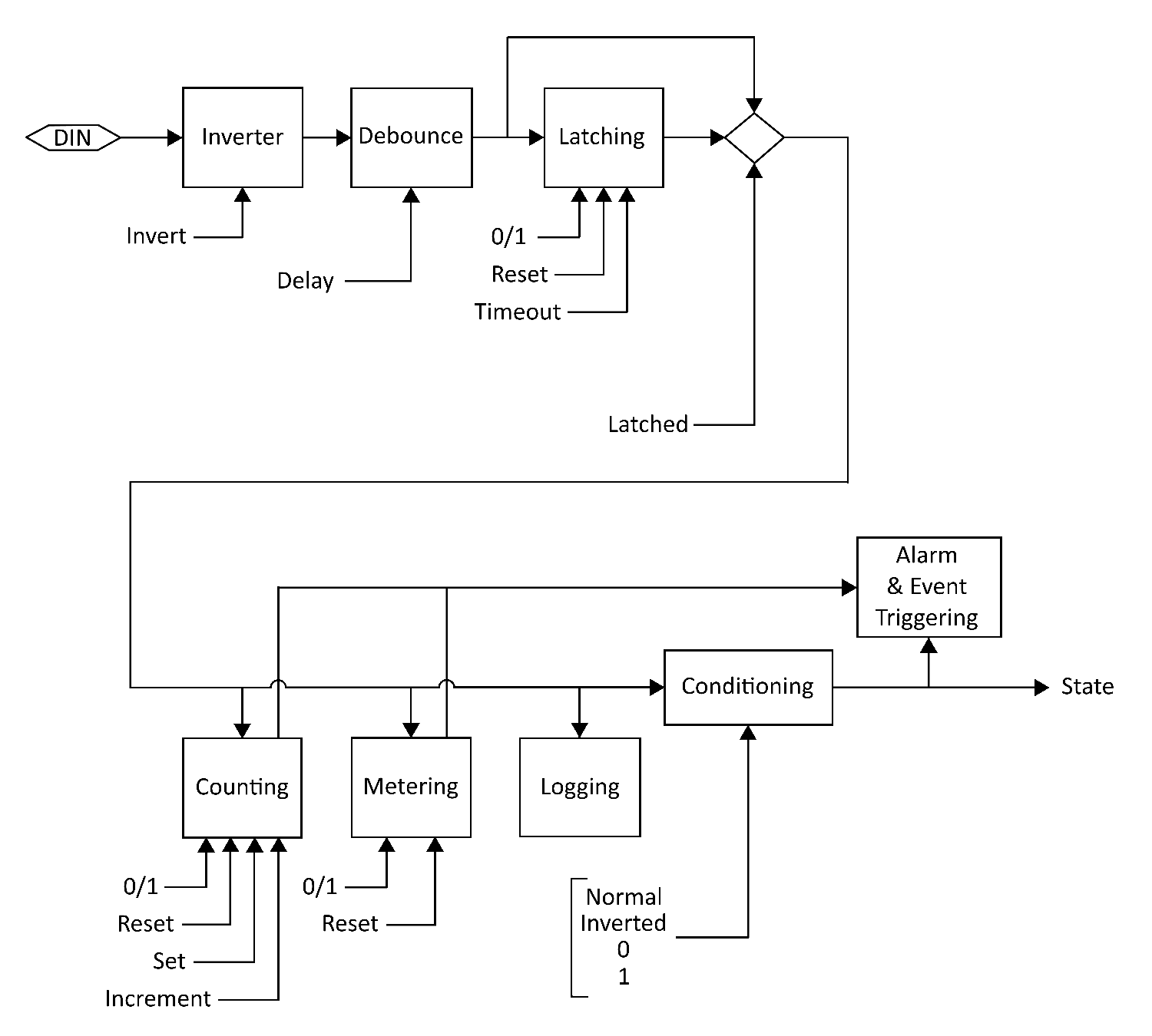
1. Sampled (Hardware)
2.
Inversion
3.
Debounce
4.
Latching
5.
Counting
6.
Metering
7.
Logging
8.
Conditioning
9.
Alarming
10. State Reported
All of the above steps are configurable through the WebUI and follow the
resulting Registry key settings.
Page 171
REGISTRY NAMING
Each Digital Input has its own Registry section (node) which is numerically
defined. Presently there can be 4, 8 or 12 inputs depending on the JNIOR
model. Here we use [DIN] as a placeholder for the appropriate section name.
For example using 'din3' for Digital Input 3 we can set a text description
as follows:
reg IO/Inputs/din3/Desc = "Power Enabled"
NOTES
Registry keys are not case-sensitive however case is preserved when a key
is first defined. This improves readability without causing difficulty
in referencing keys.
SEE ALSO
HELP Topics:
IO/Inputs/[DIN]/Desc,
REG,
MODELS,
INPUTS
Inversion Inputs
DESCRIPTION
A Digital Input may be configured to be read as ON when no voltage is
applied to the input and be considered OFF when the LED associated with the
input is actually illuminated. This is the case when the input is 'Inverted'.
The inversion can be accomplished in two different ways. The input signal
may be inverted as it is sampled by the system. It can also be inverted as
it is reported by the system. The difference is in how other input features
perceive the input state.
Sampled Inversion
The input Debounce, Latching, Counting, Metering, and Logging features
operate on the input state as it is sampled. When Inversion is applied
to the sampled input all of these features see and respond to the inverted
input state. This is useful in accommodating an input signal whose voltage
works with opposite meaning (5VDC means not active for instance).
Conditioned Inversion
When an application uses an input state in a sense opposite in meaning to
the signal itself, it may be appropriate to invert the reported state. In
this case input features work logically and the application is still
satisfied. The
Inversion is applied as a form of state
Conditioning
prior to reporting.
NOTES
State Alarming reflects the reported state. Counting and Metering (Usage)
alarms result from the sampled state.
Both Counting and Metering can be configured to respond to either a '0'
or '1' state. In effect these each have their own type of inversion. There
is sufficient flexibility to accommodate whatever is needed.
Page 172
SEE ALSO
HELP Topics:
IO/Inputs/[DIN]/Inversion,
IO/Inputs/[DIN]/Conditioning
Debouncing Inputs
DESCRIPTION
Relays and switches have mechanical contacts which physically make or break
a circuit. Rarely will the contacts come together solidly or separate
decisively without bouncing (briefly making and breaking the circuit). This
can raise havoc with digital latching and counting circuits that might be
monitoring through the relay/switch contact. It can result in latching at the
wrong time (when the relay opens for instance) or in extra counts. Both are
undesirable.
An input transition is sampled on either the input turning ON or turning OFF.
When an input changes after being stable longer than the defined Debounce
delay the input transition is immediately reported and processed. This
eliminates filtering delay.
The Debounce delay timer is restarted with each input transition. When the
timer is active additional transitions are not processed. This ignores
noise from switch and relay contact bounce.
When the Debounce timer expires the state of the input is updated to reflect
its current status. In effect this accomplishes pulse stretching. A short
input pulse shorter than the defined delay will activate the input which
will remain active until the delay expires. This can be long after the pulse
completed.
NOTES
Another way to capture short input pulses is
Latching. This can be
configured to accomplish pulse stretching as well. Additionally a pulse
may be captured and require a manual reset through Latching.
Debounce can also be used to achieve a stable state detecting the presence
of an AC voltage. In order to avoid counting each period of a 60Hz AC voltage
the Debounce setting needs to be at least 167 milliseconds. The default
setting of 200 milliseconds is perfect for that. The input detects the
presence of the voltage and gives a steady ON result. Note though that an
input is rated only to 30V.
SEE ALSO
HELP Topics:
IO/Inputs/[DIN]/Debounce,
INPUTS,
LATCHING
Latching Inputs
DESCRIPTION
When pulsed signals are applied to a Digital Input the input state may
change so fast that it cannot be seen or detected by an application. The
solution is to capture the pulse and hold the signal state long enough
Page 173
to be detected and then processed. An input can be configured to latch on
either the 1 (ON) state or the 0 (OFF) state. A pulse as short a 1 milli-
second can be detected.
Once latched a timer can be configured to reset the latch after a period
suitable for the application. Alternatively the latch might hold the
condition indefinitely until it is manually reset or acknowledged by the
application programming. This may be appropriate in a fire alarm situation.
NOTES
Pulses may also be stretched using Debounce.
SEE ALSO
HELP Topics:
IO/Inputs/[DIN]/Latching,
DEBOUNCE
Logging Inputs
DESCRIPTION
Individual changes in I/O state are accurately logged. The
IOLOG command
can be used to display and save I/O logs. Applications have the ability to
query I/O log detail with sufficient accuracy to calculate information such
as the RPM (Revolutions Per Minute) of a wind turbine both at high speeds
and very low speeds (fractions of RPM). The I/O logs can be used in
preference to monitoring the input state itself.
EXAMPLE
I/O Log content:
06/10/21 13:00:45.487, DIN ---- 0000 0000, RLY ---- ---- 0000 0000
06/11/21 11:10:41.197, DIN ---- 0000 0000, RLY ---- ---- 0000 0001
06/11/21 11:10:41.297, DIN ---- 0000 0000, RLY ---- ---- 0000 0000
06/11/21 13:23:29.008, DIN ---- 0000 0000, RLY ---- ---- 0000 0001
06/11/21 13:23:31.008, DIN ---- 0000 0000, RLY ---- ---- 0000 0000
06/11/21 13:23:34.813, DIN ---- 0000 0000, RLY ---- ---- 0000 0001
06/11/21 13:23:34.913, DIN ---- 0000 0000, RLY ---- ---- 0000 0000
06/11/21 13:28:30.665, DIN ---- 0000 0000, RLY ---- 0001 0000 0000
06/11/21 13:28:39.023, DIN ---- 0000 0000, RLY ---- 0001 0000 0010
06/11/21 13:30:24.665, DIN ---- 0000 0000, RLY ---- 0000 0000 0000
Note that in this example an external Power 4ROUT was added a one point
and one of its relays closed and later opened.
NOTES
High frequency input signals can impact product performance and logging for
individual inputs may be disabled if that is of concern. It may be more that
a frequently changing signal may mask the activity of other inputs given
that the I/O log queue itself is of a fixed size.
SEE ALSO
HELP Topics:
IO/Inputs/Log,
IOLOG,
JRMON
Page 174
IO/Inputs/Log Registry Key
NAME
IO/Inputs/Log
DEFAULT
enabled
DESCRIPTION
This key can be used to disable logging of all of the Digital Inputs
regardless of the logging settings for individual inputs. This setting
does require a reboot to take effect.
NOTES
You might consider disabling input logging if input signals change more than
a few times per second. Applications however can refer to the I/O log to
perform calculations such as averaging for reporting information such as
Revolutions per Minute (RPMs).
SEE ALSO
HELP Topics:
IO/Inputs/[DIN]/Log,
LOGGING,
IOLOG
Metering Inputs
DESCRIPTION
JANOS performs Usage Metering for both Ditigal Inputs and Relay Outputs.
This tallies the amount of time that either input or output remains in a
defined state. By default this is the ON or 1 state for inputs and the CLOSED
or 1 state for relays. The accumulated time is maintained to the millisecond
and can be viewed through the Registry to the tenth of an hour. The JRMON
command can also display usage meters. These are also displayed by the
WebUI.
These meters may be used for preventative maintenance. A Usage Alarm can be
enabled to transmit an email notification when a service interval may be
approaching.
SEE ALSO
HELP Topics:
$HOURMETER,
JRMON,
DIN
Counting Inputs
DESCRIPTION
JANOS tallies the number of times a Digital Input enters a predefined state.
By default the count reflects the ON or 1 input state. A counter is advanced
each time the input transitions from the OFF 0 state to the ON 1 state.
The counters may be viewed, set and reset using the JRMON command. They are
also displayed by the WebUI. Applications may also utilize and manage counts.
Page 175
Alarms may be set and configured to send an email when counts reach either
of two separate trigger points (Alarm1 and Alarm2).
SEE ALSO
HELP Topics:
ALARMING,
DIN,
JRMON
Alarming Inputs
DESCRIPTION
JANOS is capable of handling a number of Alarm situations. These are events
that can be enabled to preform an action or issue a notification. By default
a notification can be configured. Applications can be written to respond to
alarms and take other actions. Alarms are reported externally through the
JMP and JNIOR protocols.
Input Alarms may be defined to react to a specific input state. For example
an input wired to a door sensor may be configured to send an email when
going to the ON state.
Alarms may be generated when an Input Counter reaches predefined values.
Two separate input counter alarm trigger points may be defined: Alarm1 and
Alarm2.
And finally, an alarm may be triggered with an Digital Input or a Relay
Output reaches a predefined Usage Metering hour total.
SEE ALSO
HELP Topics:
JMP,
JPROTOCOL,
Events/OnAlarm,
EventsOnAlarm1,
Events/OnAlarm2
Events/OnUsage
Text Descriptions Registry Key
NAME
IO/Inputs/[DIN]/Desc
DEFAULT
"Digital Input ##"
DESCRIPTION
This defines a textual description for the associated Digital Input. This
Registry key is not specifically used by the operating system. It is used
by the WebUI and can be referenced by any other application desiring a
description for the input.
ON STATE
IO/Inputs/[DIN]/OnDesc
DEFAULT
"On"
Page 176
DESCRIPTION
This defines the text used to describe the state when the associated input
is ON. By default an input is considered to be ON when sufficient voltage
is applied illuminating the associated LED.
This Registry key is not specifically used by the operating system. It is
used by the WebUI and can be referenced by any other application desiring
a description for the input state.
NOTES
An input may be configured to be Inverted either as JANOS perceives the
input state or as it is reported. The associated LED follows the voltage
state of the input. Depending on configuration the system may report a
different condition.
OFF STATE
IO/Inputs/[DIN]/OffDesc
DEFAULT
"Off"
DESCRIPTION
This defines the text used to describe the state when the associated input
is OFF. By default an input is considered to be OFF when the associated
LED is not illuminated.
This Registry key is not specifically used by the operating system. It is
used by the WebUI and can be referenced by any other application desiring
a description for the input state.
NOTES
An input may be configured to be Inverted either as JANOS perceives the
input state or as it is reported. The associated LED follows the voltage
state of the input. Depending on configuration the system may report a
different condition.
SEE ALSO
HELP Topics:
IO/Inputs/[DIN]/Inversion,
DIN,
INPUTS
IO/Inputs/[DIN]/Inversion Registry Key
NAME
IO/Inputs/[DIN]/Inversion
DEFAULT
disabled
DESCRIPTION
When this Registry key is enabled the JNIOR will invert the sense of the
Digital Input as it is sampled. When enabled the input will be considered
OFF when sufficient voltage is applied to the external circuit causing the
associated LED to be illuminated.
Page 177
This inversion is applied immediately to the input and affects all other
subsequent functions (Debounce, Latching, Alarming, Counting, etc.).
SEE ALSO
HELP Topics:
IO/Inputs/[DIN]/Conditioning,
DIN
IO/Inputs/[DIN]/Conditioning Registry Key
NAME
IO/Inputs/[DIN]/Conditioning
DEFAULT
0 (Normal)
DESCRIPTION
The input state may be Cconditioned prior to being reported and after all
other operations. By default the input state is as reported by the latching
or debounce stages (Mode 0). You may configure inversion here or force the
input to be always read as 0 (OFF) or 1 (ON). Note that counting and usage
metering remain operational even when inputs are forced to a fixed state.
The following settings are valid:
0 Normal (no change)
1 Inverted
2 Forced to 0 (OFF) state
3 Forced to 1 (ON) state
A value other than those above will be handled as if set to the default.
SEE ALSO
HELP Topics:
IO/Inputs/[DIN]/Debounce,
DIN,
INVERSION
IO/Inputs/[DIN]/Debounce Registry Key
NAME
IO/Inputs/[DIN]/Debounce
DEFAULT
200 (milliseconds)
DESCRIPTION
This defines the Debounce Delay in milliseconds.
Relays and switches have mechanical contacts which physically make or break
a circuit. Rarely will the contacts come together solidly or separate
decisively without bouncing (briefly making and breaking the circuit). This
can raise havoc with digital latching and counting circuits that might be
monitoring through the relay/switch contact. It can result in latching at the
wrong time (when the relay opens for instance) or in extra counts. Both are
undesirable.
Page 178
By default the JNIOR digital inputs are debounced . An input must remain
quiet (not change) for the specified delay before any transition on that
input will be processed (latched, counted or logged).
This is sufficient to eliminate most all of the issues arising from contact
bounce.
A setting of 0 disables the debounce. In this case the JNIOR is capable of
counting transitions occurring at rates up to roughly 1,800 per second.
SEE ALSO
HELP Topics:
IO/Inputs/[DIN]/Latching,
DEBOUNCE,
DIN
IO/Inputs/[DIN]/Latching Registry Key
NAME
IO/Inputs/[DIN]/Latching
DEFAULT
disabled
DESCRIPTION
Enable this Registry key when the associated input is to be latched. When
enabled, the input will be considered to remain in the state defined by the
LatchState setting after the voltage applied to the external input is
changed. If the LatchTime is set to 0 seconds the User must manually reset
the input. This can be done through the WebUI or other application.
SEE ALSO
HELP Topics:
IO/Inputs/[DIN]/LatchTime,
IO/Inputs/[DIN]/LatchState,
DIN
IO/Inputs/[DIN]/LatchTime Registry Key
NAME
IO/Inputs/[DIN]/LatchTime
DEFAULT
0.0 (seconds)
DESCRIPTION
This defines the time in seconds (0.1 equals 100 milliseconds) that an input
remains latched before being automatically reset. A value of 0.0 will require
the user to separately reset the latched input through an application or
the
JRMON command.
SEE ALSO
HELP Topics:
IO/Inputs/[DIN]/LatchState,
DIN,
JRMON
Page 179
IO/Inputs/[DIN]/LatchState Registry Key
NAME
IO/Inputs/[DIN]/LatchState
DEFAULT
1 (ON)
DESCRIPTION
When Latching is enabled this specifies whether the input is latched in the
ON state (1) or in the OFF state. The key is set to 1 or 0 respectively.
SEE ALSO
HELP Topics:
LATCHING,
DIN
IO/Inputs/[DIN]/Log Registry Key
NAME
IO/Inputs/[DIN]/Log
DEFAULT
enabled
DESCRIPTION
This key can be optionally used to disable logging on an input by input
basis. If an input is going to be rapidly changing the time spent in the
logging process can degrade system performance. In such circumstances it
is suggested that logging can be disabled for the input.
SEE ALSO
HELP Topics:
IO/Inputs/Log,
LOGGING,
IOLOG
IO/Inputs/[DIN]/$HourMeter Registry Key
NAME
IO/Inputs/[DIN]/$HourMeter
DESCRIPTION
This dynamic key reports the total number of hours that a digital input has
physically been in the state specified by UsageState . This value is
nonvolatile and maintains its content through power removal and until it
is specifically reset. It is reported here in hours to the one-hundredth.
The Hour Meter is accurate to the millisecond and this high resolution value
may be read through the JMP Protocol, the JNIOR Protocol or using the JRMON
command.
SEE ALSO
HELP Topics:
METERING,
JMP,
JPROTOCOL,
JRMON,
DIN
Page 180
IO/Inputs/[DIN]/Alarming Registry Key
NAME
IO/Inputs/[DIN]/Alarming
DEFAULT
disabled
DESCRIPTION
When enabled an alarm is generated when then associated input enters the
specified state. By default the alarm is issued when the conditioned
state for the input indicates that the input has turned ON.
NOTES
Inputs may be inverted when sampled, latched and/or conditioned prior to
being monitored for alarming.
SEE ALSO
HELP Topics:
IO/Inputs/[DIN]/Alarm/Inversion,
DIN,
INVERSION,
LATCHING
CONDITIONING,
ALARMING
IO/Inputs/[DIN]/Alarm/Inversion Registry Key
NAME
IO/Inputs/[DIN]/Alarm/Inversion
DEFAULT
disabled
DESCRIPTION
This setting defines the state triggering the alarm. Enable this key when
the associated input is to alarm upon entering the OFF state. This inverts
the input state prior to alarm monitoring and essentially changes the
triggering state. By default an alarm normally is generated when the input
turns ON.
SEE ALSO
HELP Topics:
IO/Inputs/[DIN]/Alarm/Email,
ALARMING,
DIN
IO/Inputs/[DIN]/Alarm/Email Registry Key
NAME
IO/Inputs/[DIN]/Alarm/Email
DEFAULT
disabled
DESCRIPTION
This key enables Email Notifications in response to a Digital Input state
Alarm.
SEE ALSO
HELP Topics:
IO/Inputs/[DIN]/Alarm/EmailBlock,
ALARMING,
DIN
Page 181
IO/Inputs/[DIN]/Alarm/EmailBlock Registry Key
NAME
IO/Inputs/[DIN]/Alarm/EmailBlock
DEFAULT
None
DESCRIPTION
This may be used define a custom Email Notification message transmitted when
the input state alarm is triggered.
SEE ALSO
HELP Topics:
IO/Inputs/[DIN]/Alarm/HoldOff,
EMAIL_BLOCK,
ALARMING,
DIN
IO/Inputs/[DIN]/Alarm/HoldOff Registry Key
NAME
IO/Inputs/[DIN]/Alarm/HoldOff
DEFAULT
300000 (milliseconds)
DESCRIPTION
This defines the amount of time in milliseconds that the Digital Input state
alarm must remain clear before any subsequent state alarm for this input will
be acted upon. The default is 300000 or 5 minutes. When an alarm occurs the
services associated with that event are performed. The alarm must reset and
remain so for this amount of time before those actions would be performed
again. Even at this setting an email notification could be sent once every
5 minutes if the input is actively changing.
SEE ALSO
HELP Topics:
ALARMING,
DIN
IO/Inputs/[DIN]/CountState Registry Key
NAME
IO/Inputs/[DIN]/CountState
DEFAULT
1 (ON)
DESCRIPTION
This specifies whether an input transition from OFF to ON is counted (1) or
if the transition from ON to OFF is counted. The key is set to either 1 or 0
respectively. By default the counters are advanced when the input state
transitions from OFF 0 to ON 1.
SEE ALSO
HELP Topics:
IO/Inputs/[DIN]/Count/Units,
COUNTING,
DIN
Page 182
IO/Inputs/[DIN]/Count/Units Registry Key
NAME
IO/Inputs/[DIN]/Count/Units
DEFAULT
"counts"
DESCRIPTION
This defines the text decribing the units to be displayed with the associated
input counter. This Registry key is not specifically used by the operating
system. It is used by the WebUI and can be referenced by any other application
requiring a description of the count units.
The units of count may vary depending on the scaling and sampling options
used. By default input transitions are simply counted and the counts are
reported.
SEE ALSO
HELP Topics:
IO/Inputs/[DIN]/Count/Multiplier,
COUNTING,
DIN
IO/Inputs/[DIN]/Count/Multiplier Registry Key
NAME
IO/Inputs/[DIN]/Count/Multiplier
DEFAULT
0.0
DESCRIPTION
When the Count Multiplier is set to 0.0 (default) the absolute counter value
is displayed. When a non-zero multiplier is specified the value is used to
scale the counter value for display. The scaled counter value is also used
for count alarm trigger points.
Input pulses are counted and each count may represent some incremental value
of a quantity measured by the remote sensor. For instance each pulse might
indicate that 5 gallons of water has passed through a flow sensor. Im this
example you might set the multiplier IO/Inputs/[DIN]/Count/Multiplier to
5.0 and the reported units IO/Inputs/[DIN]/Count/Units to "Gallons". The
WebUI would then report the accumulated gallons as measured.
SEE ALSO
HELP Topics:
IO/Inputs/[DIN]/Count/SampleTime,
IO/Inputs/[DIN]/Count/Units
COUNTING,
DIN
Page 183
IO/Inputs/[DIN]/Count/SampleTime Registry Key
NAME
IO/Inputs/[DIN]/Count/SampleTime
DEFAULT
0.0 (seconds)
DESCRIPTION
This defines a sampling period in seconds. A fractional value may be
specified.
Normally Counts accumulate until reset separately by the user threw the
WebUI, JRMON or other application. This is the case when SampleTime is
set to 0.0 (default). When a nonzero time is defined the counter displays
the total count accumulated during that period. For instance, with the
appropriate combination of Multiplier and SampleTime the counter can
display Revolutions Per Minute (RPM) for a input using a Hall Effect
sensor mounted on a wheel hub.
NOTES
When RPM is measured in this fashion it is perhaps better to allow an
application to perform the calculation. With access to the I/O log and
the appropriate Java class the application can average pulses over a
moving window or sample time for the accurate real-time measurement of
high RPMs. When the wheel is rotating extremely slowly the application can
then use the pulse-to-pulse timing to derive an estimate of fractional RPMs
and even the rate of change. This would be a useful approach for use with
a wind turbine as an example.
SEE ALSO
HELP Topics:
JRMON,
COUNTING,
DIN
Count Alarms Registry Key
ALARM ENABLES
IO/Inputs/[DIN]/Count/Alarm1
IO/Inputs/[DIN]/Count/Alarm2
DEFAULT
disabled
DESCRIPTION
Set to enable an alarm when the scaled count exceeds the Limit1 or Limit2
value as appropriate.
TRIGGER POINTS
IO/Inputs/[DIN]/Count/Limit1
IO/Inputs/[DIN]/Count/Limit2
DEFAULT
0 (zero)
Page 184
DESCRIPTION
This defines the trigger point for the associated count alarm. An alarm can
be generated when the scaled counter exceeds this value.
SEE ALSO
HELP Topics:
COUNTING,
DIN
Counter Alarm Email Registry Key
EVENT ENABLE
IO/Inputs/[DIN]/Alarm1/OnAlarm
IO/Inputs/[DIN]/Alarm2/OnAlarm
DEFAULT
disabled
DESCRIPTION
Set this key to enable services related to the occurrence of Digital Input
Counter Alarms on this input.
HOLDOFF
IO/Inputs/[DIN]/Alarm1/HoldOff
IO/Inputs/[DIN]/Alarm2/HoldOff
DEFAULT
300000 (milliseconds)
DESCRIPTION
This defines the amount of time in milliseconds that the Digital Input counter
alarm must remain clear before any subsequent alarm on this input will be
acted upon. The default is 300000 or 5 minutes.
When an alarm occurs the services associated with that event are performed.
The alarm must reset and remain so for this amount of time before those
actions would be performed again.
EMAIL ENABLE
IO/Inputs/[DIN]/Alarm1/Email
IO/Inputs/[DIN]/Alarm2/Email
DEFAULT
disabled
DESCRIPTION
This Registry key enables the Alarm Notification email.
CUSTOM EMAIL NOTIFICATION
IO/Inputs/[DIN]/Alarm1/EmailBlock
IO/Inputs/[DIN]/Alarm2/EmailBlock
Page 185
DEFAULT
None
DESCRIPTION
This may be used define a block that creates a unique Alarm Notification
message.
SEE ALSO
HELP Topics:
EMAIL_BLOCK,
COUNTING,
DIN
Usage Registry Key
METERED STATE
IO/Inputs/[DIN]/UsageState
DEFAULT
1 (ON)
DESCRIPTION
This specifies whether usage time is accumulated with the input in the ON
state (1) or in the OFF state (0). The key is set to 1 or 0 respectively.
ALARM ENABLE
IO/Inputs/[DIN]/Usage/Alarm
DEFAULT
disabled
DESCRIPTION
Set this Registry key to enable an alarm when the associated usage meter
reaches a specified number of hours.
USAGE LIMIT
IO/Inputs/[DIN]/Usage/Limit
DEFAULT
0.0
DESCRIPTION
Defines the alarm setpoint in hours and fractions of hours. The associated
input goes into alarm when the usage meter reported by $HourMeter reaches
or exceeds this setpoint.
EVENTS ENABLE
IO/Inputs/[DIN]/Usage/OnAlarm
DEFAULT
disabled
Page 186
DESCRIPTION
This key may be optionally defined to enable services related to Digital
Input Usage Alarms.
EMAIL ENABLE
IO/Inputs/[DIN]/Usage/Email
DEFAULT
disabled
DESCRIPTION
This Registry key enables Usage Notification email.
CUSTOM NOTIFICATION
IO/Inputs/[DIN]/Usage/EmailBlock
DEFAULT
None
DESCRIPTION
This may be used define a block that creates a unique Usage Notification
message.
HOLDOFF
IO/Inputs/[DIN]/Usage/HoldOff
DEFAULT
300000 (milliseconds)
DESCRIPTION
This defines the amount of time in milliseconds that the Digital Input usage
alarm must remain clear before any subsequent usage alarm on this input will
be acted upon. The default is 300000 or 5 minutes.
When an alarm occurs the services associated with that event are performed.
The alarm must reset and remain so for this amount of time before those
actions would be performed again.
SEE ALSO
HELP Topics:
$HOURMETER,
JRMON,
DIN
Relay Outputs Registry Key
OVERVIEW
The following keys are associated with the Relay Outputs. In each of the
keys replace the [ROUT] with the appropriate string with channel number ROUT1
thru ROUT16 depending on the configuration. The Model 410 has 8 relay outputs
while the Model 412 has 12 and the Model 414 only 4. Power 4ROUT Expansion
Modules may be added to provide additional relays. The first 16 are addressable
through the Registry.
Page 187
IO/Outputs/[ROUT]/Desc Registry Key
NAME
IO/Outputs/[ROUT]/Desc
DEFAULT
"Relay Output ##"
DESCRIPTION
This defines the textual description for the associated Relay Output. This
Registry key is not specifically used by the operating system. It is used
by the WebUI and can be referenced by any other application requiring a
description.
CLOSED STATE
IO/Outputs/[ROUT]/ClosedDesc
DEFAULT
"Closed"
DESCRIPTION
This defines the text shown when the associated relay has been activated
and is in the CLOSED state. This Registry key is not specifically used by
the operating system. It is used by the WebUI and can be referenced by any
other application requiring a description of the output status.
OPEN STATE
IO/Outputs/[ROUT]/OpenDesc
DEFAULT
"Open"
DESCRIPTION
This defines the text shown when the associated relay is in the OPEN state.
This Registry key is not specifically used by the operating system. It is
used by the WebUI and can be referenced by any other application requiring
a description of the output status.
IO/Outputs/[ROUT]/InitialState Registry Key
NAME
IO/Outputs/[ROUT]/InitialState
DEFAULT
undefined
DESCRIPTION
This key is used to define the initial behavior of relay outputs on boot.
Page 188
The value defines a pulse duration in milliseconds where an entry of 0
indicates infinity. Setting the key to a value of 0 would effectively
close the output. Setting the key to a positive integer would cause the
output to pulse for the duration defined by the value An undefined or
negative value (default) results in no action.
NOTES
On power up all relays are in the inactive state. By default that is the
OPEN state where the contacts are not conducting. These are Normally Open
(NO) contacts. Depending on the model certain relays may be reconfigured by
internal jumper to be Normally Closed (NC). These would be conducting after
boot. Consider this option if you need a relay to conduct when the JNIOR
is powered down or after it reboots.
IO/Outputs/[ROUT]/$HourMeter Registry Key
NAME
IO/Outputs/[ROUT]/$HourMeter
DESCRIPTION
This dynamically reports the total number of hours that the relay output
has been in the CLOSED state. This value is non-volatile maintaining content
through power loss and until it is specifically reset. It is reported here
in hours to the one-hundredth. The Hour Meter is accurate to the millisecond
and this high resolution value may be read through the JMP Protocol, the
JNIOR Protocol or using the JRMON command.
SEE ALSO
HELP Topics:
JRMON,
HOURMETER,
JMP,
JPROTOCOL
Usage Registry Key
NAME
IO/Outputs/[ROUT]/UsageState
DEFAULT
1 (CLOSED)
DESCRIPTION
This specifies whether usage time is accumulated when the relay is in the
CLOSED state (1) or in the OPEN state (0). The key is set to 1 or 0
respectively.
Note that certain relays may be reconfigured from Normally Open (NO) to
Normally Closed (NC) by jumper. This may affect the choice of metering
state.
ALARM ENABLE
IO/Outputs/[ROUT]/Usage/Alarm
Page 189
DEFAULT
disabled
DESCRIPTION
Set to enable an alarm when the associated usage meter reaches the Limit
specified.
USAGE LIMIT
IO/Outputs/[ROUT]/Usage/Limit
DEFAULT
0.0
DESCRIPTION
Defines the alarm setpoint in hours and may include a fractional part. The
associated relay output goes into alarm when the usage meter reaches or
exceeds this setpoint.
EVENTS ENABLE
IO/Outputs/[ROUT]/Usage/OnAlarm
DEFAULT
disabled
DESCRIPTION
This key may be optionally defined to enable services related to Relay
Output Usage Alarms.
EMAIL ENABLE
IO/Outputs/[ROUT]/Usage/Email
DEFAULT
disabled
DESCRIPTION
This Registry key enables Usage Notification email.
CUSTOM EMAIL NOTIFICATION
IO/Outputs/[ROUT]/Usage/EmailBlock
DEFAULT
None
DESCRIPTION
This may be used define a block that creates a unique Usage Notification
message.
HOLDOFF
IO/Outputs/[ROUT]/Usage/HoldOff
Page 190
DEFAULT
300000 (milliseconds)
DESCRIPTION
This defines the amount of time in milliseconds that the Relay Output usage
alarm must remain clear before any subsequent usage alarm on this input will
be acted upon. The default is 300000 or 5 minutes.
When an alarm occurs the services associated with that event are performed.
The alarm must reset and remain so for this amount of time before those
actions would be performed again.
SEE ALSO
HELP Topics:
EMAIL_BLOCK
Output Logging Registry Key
LOGGING ENABLE
IO/Outputs/Log
DEFAULT
enabled
DESCRIPTION
This key can be used to disable logging of all of the Relay Outputs. This
setting requires a reboot.
ENABLE BY OUTPUT
IO/Outputs/[ROUT]/Log
DEFAULT
enabled
DESCRIPTION
This key can be optionally used to disable logging on an output by output
basis. If an output is going to be rapidly changing the time spent in the
logging process can degrade system performance. In such circumstances it is
recommended that logging be disabled for the relay output.
NOTES
The logging process would impact performance significantly with Series 3
JNIOR (Models 310, 312 and 314). This was due to the fact that I/O changes
were immediately logged to the jniorio.log file. With Series 4 JNIOR
(Models 410, 412, 414 and 412DMX) I/O changes are queued in high-speed
local memory. This process has little if any impact on performance. The
jniorio.log file is then generated on-demand using the IOLOG console
command.
SEE ALSO
HELP Topics:
IOLOG
Page 191
Serial Comm Registry Key
OVERVIEW
The JNIOR (Models 410, 412 and 414) support two serial ports, the
COM RS-232
Port and the
AUX Serial port. Both ports may be used by application programs
to communicate with and control other devices. By default the COM port
provides Diagnostic output information which generally reports status
during the boot process. Once the product is up and running the COM port
may be used to access to the JANOS Command Line Console. This can be disabled
using the
MODE command to insure dedicated communications with external
equipment.
The default communications parameters are 115.2K baud, 8 data bits, 1 stop
bit with no parity or handshake. The COM port supports only 3-wire
communications. This port does not include hardware handshake lines. The
AUX port provides for RTS and CTS handshake signals which may be optionally
enabled. In addition the AUX port on the Model 410 may be configured for
RS-422 or RS-485 communications. In the latter case the output driver may
be software controlled supporting multi-drop serial networks.
NOTES
Access to the Command Line Console may be enabled for the AUX Serial port
on a session by session basis using the MODE command.
The AUX Serial port is also supported by the
IOLOG command. A bi-directional
transmission log is maintained showing recent communications. This data can
be displayed or saved to an auxio.log file for further analysis. It is a
very useful diagnostic tool.
The Model 412DMX eliminates the AUX Serial port. It is replaced by a dedicated
DMX512 Universe 5-pin output.
SEE ALSO
HELP Topics:
MODELS,
COM,
AUX,
MODE,
IOLOG
AUX Serial Registry Key
OVERVIEW
The
AUX Serial port is available on Models 410, 412, and 414 JNIOR products.
It is located at the top of the JNIOR next to the POWER and Sensor Port
Expansion Bus connections. This port supports RS-232 communications with
optional capability for RTS/CTS hardware handshake. A software XON/XOFF
handshake for pacing communications is also possible.
The Model
410 additionally supports RS-422 and RS-485 communications that
provide longer distance communications capabilities or multi-device serial
networking. It is possible to configure a Model 410 to generate a standard
DMX512 Universe output for controlling stage lighting.
NOTES
The AUX Serial Port is not available on the Model 412DMX. This is replaced
Page 192
by a dedicated 5-pin DMX output channel.
SEE ALSO
HELP Topics:
AUX_PORT
AUX Serial Registry Key
BAUDRATE
AUXSerial/Baudrate
DEFAULT
115200 (115.2 kBaud)
DESCRIPTION
The default baud rate is 115.2K baud. The communications baud rate may be
modified through this Registry key either directly, by application program
or using the WebUI. Valid settings are:
250000, 128000, 115200, 57600, 38400, 31250, 28800, 19200,
14400, 9600, 4800, 2400, 1200, 600, 300, 150, and 110
The 250K baud setting is for supporting the DMX512 standard used by stage
lighting equipment over RS-485.
SEE ALSO
HELP Topics:
AUX_PORT,
AUX_FLOW
AUX Serial Registry Key
DATABITS
AUXSerial/Databits
DEFAULT
8 (bits)
DESCRIPTION
The default setting is 8 data bits. Valid settings are 7 and 8. The 7 data
bit mode is most often used with either ODD or EVEN parity wherein the parity
bit is added maintaining the normal 8 bit stream.
SEE ALSO
HELP Topics:
AUX_PORT,
AUX_FLOW
AUX Serial Registry Key
STOPBITS
AUXSerial/Stopbits
Page 193
DEFAULT
1 (bits)
DESCRIPTION
The default setting is 1 stop bit. Valid settings are 1 or 2. The typical
asynchronous receiver always recognizes the end of a character using a single
stop bit since there can be any amount of time between characters unless the
protocol specifically sets a timeout. The transmitter uses this stop bit
setting to stretch the minimum time between characters by one extra bit time.
SEE ALSO
HELP Topics:
AUX_PORT,
AUX_FLOW
AUX Serial Registry Key
PARITY
AUXSerial/Parity
DEFAULT
NONE
DESCRIPTION
The default setting is for No Parity (NONE or 0). Valid settings are 0, 2
and 3 where 0 means No Parity or NONE, 2 indicates EVEN parity and 3 ODD
parity. An additional bit is added to the transmitted stream when EVEN or
ODD parity is specified. When either EVEN or ODD is specified the received
data is expected to contain a parity bit which is checked and removed. This
bit is in addition to that specified by the data bit setting.
SEE ALSO
HELP Topics:
AUX_PORT,
AUX_FLOW
AUXSerial/Flow Registry Key
NAME
AUXSerial/Flow
DEFAULT
0 (NO_CONTROL)
DESCRIPTION
The default setting is NO_CONTROL or 0 meaning that no flow control or
handshaking either by hardware or software is used. For the AUX port the
valid settings are:
0 (NO_CONTROL)
1 (RTSCTS_IN)
2 (RTSCTS_OUT)
3 (RTSCTS)
Page 194
4 (XONXOFF_IN)
8 (XONXOFF_OUT)
12 (XONXOFF)
The RTSCTS_IN setting uses the available CTS hardware handshake line to
control the flow of data from an external source (IN). To hold off incoming
data the JNIOR activates the CTS line when internal buffers near capacity.
In RTSCTS_OUT mode the AUX port monitors the RTS line and stops transmission
when it is activated. The RTSCTS mode employs the handshake bidirectionally.
The XONXOFF_IN handshake transmits the XOFF character (Ctrl-S 0x13) when
internal buffers reach capacity to hold off the incoming data. The XON
character (Ctrl-Q 0x11) is later sent to resume communications. Similarly in
XONXOFF_OUT mode the AUX port listens for the XOFF character and stops
transmission when received. When a subsequent XON character is received the
communications resume. Both the XON and XOFF characters are filtered from
the stream. The XONXOFF setting applies these rules bidirectionally.
SEE ALSO
HELP Topics:
AUX_PORT,
AUX_RS485,
ASCII
Page 195
AUXSerial/RS485 Registry Key
NAME
AUXSerial/RS485
DEFAULT
disabled
DESCRIPTION
By default the RS485 mode is disabled. RS485 communications are only available
with the Model
410 JNIOR. When enabled the RX, TX, RTS and CTS lines are
reconfigured. The transmit drivers are disabled and can be controlled by the
application program.
Originally the Model 410 JNIOR included internal jumpers allowing the unit
to be configured for RS-422 or RS-485 wiring including optional termination
resistors. In general these requirements are now achieved with external
wiring. Some 410 PCBs still have an unpopulated location for jumpers that
may be used.
SEE ALSO
HELP Topics:
AUX_PORT,
AUX_FLOW
COM Serial Registry Key
OVERVIEW
The COM RS-232 port is located at the bottom of the JNIOR next to the Ethernet
LAN connector. This port supports 3-wire RS-232 communications with
optional capability for software XON/XOFF handshake for pacing communications.
By default the COM port also provides diagnostic output during boot and
serves as a serial access point to the Command Line Console. This port is
available for connection to remote equipment.
In connecting a remote serial device it is recommended that you first use
the
AUX port. The AUX port is by default dedicated to application use; It
is supported by IOLOG providing comprehensive transmission logging; It
provides no unexpected output such as diagnostics; And, there are additional
communications lines and communication modes.
NOTES
The MODE -S command can be used to silence diagnostic output and to disable
access to the Command Line Console. The Boot Dialog may also be disabled
through the WebUI under the Serial I/O Configruation tab.
SEE ALSO
HELP Topics:
COM_PORT,
AUX_PORT,
MODE,
IOLOG
Page 196
COMSerial/BootDialog Registry Key
NAME
COMSerial/BootDialog
DEFAULT
enabled
DESCRIPTIOTN
The
COM port by default supplies reports during the boot process. Once the
unit is up and running this port can also be used to access the command
line console. When the port is employed in communicating with another device
these messages can cause protocol issues. The unwanted messages can be
disabled using this Registry key.
Note that the application program should also disable the boot dialog and
command line capabilities to insure reliable port use. This is done using
the com.integpg.comm.COMSerialPort.setBootDialog() static method. This
can also be controlled from the command line using the MODE -S command.
Diagnostic port information is included in the jniorboot.log file. This
eliminates the prior need to observe the boot through the serial port while
debugging. Additionally, the jniorboot.log.bak file accumulates prior boot
detail providing an expanded record of boot detail.
NOTES
Log retention can be greatly expanded by running the
JBakup utility.
SEE ALSO
HELP Topics:
COM_PORT,
MODE,
JBAKUP
COM Serial Registry Key
BAUDRATE
COMSerial/Baudrate
DEFAULT
115200 (115.2 kBaud)
DESCRIPTION
The default baud rate is 115.2K baud. The communications baud rate may be
modified through this Registry key either directly, by application program
or using the WebUI. Valid settings are:
250000, 128000, 115200, 57600, 38400, 31250, 28800, 19200,
14400, 9600, 4800, 2400, 1200, 600, 300, 150, and 110
Page 197
COM Serial Registry Key
DATABITS
COMSerial/Databits
DEFAULT
8 (bits)
DESCRIPTION
The default setting is 8 data bits. Valid settings are 7 and 8. The 7 data
bit mode is most often used with either ODD or EVEN parity wherein the
parity bit is added maintaining the normal 8 bit stream.
COM Serial Registry Key
STOPBITS
COMSerial/Stopbits
DEFAULT
1 (bits)
DESCRIPTION
The default setting is 1 stop bit. Valid settings are 1 or 2. The typical
asynchronous receiver always recognizes the end of a character using a single
stop bit since there can be any amount of time between characters unless the
protocol specifically sets a timeout. The transmitter uses this stop bit
setting to stretch the minimum time between characters by one extra bit time.
COM Serial Registry Key
PARITY
COMSerial/Parity
DEFAULT
0 (NONE)
DESCRIPTION
The default setting is for No Parity (NONE or 0). Valid settings are 0, 2
and 3 where 0 means No Parity or NONE, 2 indicates EVEN parity and 3 ODD
parity. An additional bit is added to the transmitted stream when EVEN or
ODD parity is specified. When either EVEN or ODD is specified the received
data is expected to contain a parity bit which is checked and removed. This
bit is in addition to that specified by the data bit setting.
SEE ALSO
HELP Topics:
COM_PORT,
COM_FLOW
COMSerial/Flow Registry Key
Page 198
NAME
COMSerial/Flow
DEFAULT
0 (NO_CONTROL)
DESCRIPTION
The default setting is NO_CONTROL or 0 meaning that no flow control or
handshaking is used. For the COM RS-232 port the valid settings are:
0 (NO_CONTROL)
4 (XONXOFF_IN)
8 (XONXOFF_OUT)
12 (XONXOFF)
The COM port does not support hardware handshaking.
The XONXOFF_IN handshake transmits the XOFF character (Ctrl-S 0x13) when
internal buffers reach capacity to hopefully hold off the incoming data.
The XON character (Ctrl-Q 0x11) is later sent to resume communications.
Similarly in XONXOFF_OUT mode the COM port listens for the XOFF character
and stops transmission when received. When a subsequent XON character is
received the communications resume. Both the XON and XOFF characters are
filtered from the stream. The XONXOFF setting applies these rules
bidirectionally.
SEE ALSO
HELP Topics:
COM_PORT,
ASCII
ZIP/JAR Compression Registry Key
OVERVIEW
JANOS supports ZIP library files. In fact the WebServer uniquely uses a ZIP
library to create virtual folders allowing an entire website to be contained
within a single file. Applications written in Java utilize a JAR library which
is nothing more than a renamed ZIP file.
ZIP/JAR files usually contain multiple files in an efficient compressed form.
The compression is performed when files are added to a library. While there
are optional compression algorithms, JANOS supports the DEFLATE compression.
This is compatible with libraries generated by most systems.
The ARC command, and its aliases ZIP and JAR, can be used at the command line
to manage a compressed library file. When adding files the necessary
compression is handled by JANOS. There are a couple of options affecting
the compression procedure and these are controlled by Registry settings.
Changes in these settings do not affect the ability to extract files from
libraries generated with other settings by the JNIOR or any remote PC.
SEE ALSO
HELP Topics:
ZIP
Zip/Window Registry Key
Page 199
WINDOW PARAMETER
Zip/Window
DEFAULT
16384
DESCRIPTION
The DEFLATE algorithm compresses a file by locating combinations of bytes
or characters that repeat. The redundancy is removed and replaced by an
efficient pointer to the original grouping. The most efficient compression
then would remove any and all redundant groups from an entire file. This is
certainly possible for small files. With large files the pointers need to
address data further and further away. As the distance grows so do the
pointers and efficiency suffers. The solution is to limit the distance using
a sliding window through the file.
By default JANOS uses a 16KB (16384 byte) sliding window. This Registry key
may be used to adjust the window from a minimum of 2KB (2048) to a maximum of
32KB (32768). In practice there should be no reason to alter this setting. A
change in this setting affects the very next compression that is performed.
DEPTH PARAMETER
Zip/Depth
DEFAULT
256
DESCRIPTION
With each successive character in a file the compressor looks back over
the sliding window for groupings where replacement by pointer would
provide the greatest compression. This is a time consuming endeavor. As a
tradeoff the JANOS routine employs a queue of likely targets in the window
for each unique character. This reduces the search effort and the time it
takes to perform the compression.
By default the search queue depth is set at 256 entries. Values may range
from a minimum of 16 to a maximum of 1024. In practice there should be no
reason to alter this setting. A change in this setting affects the very
next compression that is performed.
SEE ALSO
HELP Topics:
ZIP,
COMPRESSION
Page 200
JMP Protocol
OVERVIEW
The JANOS Management Protocol (JMP) is available to remote devices and
computers for control and management of the JNIOR. Available by default
on Port 9220 this protocol replaces the deprecated JNIOR Protocol and
provides for better security and a greater range of capabilities. The
protocol is based on the
JSON data-interchange format.
The JNIOR WebUI also uses JMP through a Websockets connection to perform
all of the functions it offers.
While the JNIOR Protocol remains a viable option for controlling and
monitoring I/O on the JNIOR the JANOS Management Protocol or JMP
(pronounced "JuMP") offers a single connection point allowing the JNIOR
to be fully managed and monitored. The older binary JNIOR Protocol can be
a challenge to implement and is not recommended for new development.
SEE ALSO
HELP Topics:
JMPCONNECT,
JSON
JMP Protocol
DESCRIPTION
There are two methods of achieving a JMP protocol connection. Both provide
access to the full capabilities of the protocol.
WEBSOCKET
A WebSocket connection creates a full-duplex communications channel as would
be available by direct connection to a TCP port but using the HTTP or HTTPS
mechanism. This enables direct interaction between a website and JANOS.
By default a WebSocket channel supports the JMP protocol. This is how the
JNIOR WebUI performs tasks such as are available through the Folders, Console
and Syslog tabs.
Websocket has been standardized by the IETF
https://www.ietf.org/ as
RFC 6455
https://tools.ietf.org/html/rfc6455 . The JNIOR WebUI is installed
by the file /flash/www/config.zip and in particular the JavaScript file
comm.js in that library handles the Websocket communications. You are free
to use that source code as reference or to incorporate any part of it in your
custom website.
Note that the JMP protocol requires a login. This is critical as the protocol
is very powerful. When a website login to the JNIOR is successful (or if the
login is disabled) a Session Cookie is generated. This is passed when a
related HTTP connection is elevated to Websocket. It then is accepted as a
valid login credential providing seamless operation.
PROTOCOL PORT
By default a connection to TCP Port 9220 provides direct access to the JMP
protocol. In this case there is a special wrapper that must be used in
transporting the JSON messages.
Page 201
One of the issues in using JSON in communications protocols stems from the
lack of message length information. In the absence of a length the
communications driver must count open '{' and close '}' curly braces in
order to ascertain when an entire structure has been read from the channel.
This is complicated by the fact that curly braces may appear in string data
and those must be ignored. The algorithm, while not complicated, is an
annoyance. The JMP connection uses a wrapper that conveys a message length.
Once a successful connection is made to the JMP Server port, messages may be
exchanged. With one exception all messages conform to the JSON format using
the ASCII printable character set. The high-level message format must be as
follows. This forms the message wrapper which is a 2-element JSON Array
construct.
[ length , object ]
Where length defines the exact size of the object in bytes excluding leading
and trailing white-space if any. Leading and trailing white-space, which can
include newline characters, may be present surrounding both the length value
and the object. Here object must be a fully formed and valid JSON Object
beginning with '{' and ending with '}' curly braces. Both these curly braces
and any characters in between are included in the length value. The leading
'[' opening square bracket, ',' comma, and trailing ']' closing square bracket
are required. The opening and closing JSON Object curly braces are also
verified. If there is any violation to this format the message will be simply
ignored. There is no response or indication of error. All bytes outside of
the square brackets are ignored as well.
A valid parsing strategy would be as follows:
* Read and ignore bytes up to a '[' opening square bracket
* Read and ignore white-space characters (space, tab, newline, etc.)
* Accumulate a decimal length (must be digits 0-9, the result must be >= 2)
* Read and ignore white-space
* Read and confirm the presence of the ',' comma
* Read and ignore white space
* Extract the JSON Object of precise length defined by the numeric value
* Read and ignore white-space
* Read and confirm the ']' closing square bracket (no other character
is acceptable)
* Confirm that the JSON object is properly enclosed by '{' and '}'
curly braces
* Process the JSON object and repeat
This wrapper is not used by the Websocket connection since Websocket already
includes message length information.
EXAMPLE
All TCP/IP Port 9220 communications utilize the 2-element JSON Array format
for conveying valid JSON Objects. This is not used in WebSocket communications.
In describing JMP protocol Messages the 2-element JSON Array format will be
assumed. We will only show the enclosed JSON Objects.
To initialize communications the client should send a blank or empty message.
The following is acceptable.
Page 202
{
"Message":""
}
This message properly formatted for JMP Port 9220 would be transmitted as
follows.
[14, {"Message":""} ]
The connection will proceed depending on the authentication requirements
established by configuration and the client environment for the connection.
NOTES
It is important to note that the TCP/IP connection is a streaming channel
and one or more network packets may be required to convey an entire message.
Similarly a packet may include the final bytes of one message and those
beginning the next. A reliable implementation will buffer incoming data until
an entire message is received. Once the message is processed it is removed
from the buffer leaving any additional data which will be required to form
the message that follows.
JMP is not Master-Slave. Many requests do solicit a response but not all.
There are also unsolicited messages produced by the server. These alert the
client to I/O changes as well as many other events.
The protocol allows you to specify any amount of META data with your
request. That data is echoed in the associated response. This can be used
to maintain synchronization between request and response. It is a very
flexible means of synchronization and can be used to convey, for example,
detailed processing instructions for the response.
SEE ALSO
HELP Topics:
SECURITY,
JMP,
JSON
JMP Protocol
SECURITY
Any protocol providing control and management functions must employ some
form of security preventing unauthorized access and abuse. By default the
JMP Server requires authentication (login). While the login requirement
may be disabled it is not recommended. When the login is disabled an account
must be specified for the anonymous login. This is configured through the
Registry. We strongly urge you to accommodate the login requirement.
In addition to user authentication the JMP Server supports a TLSv1.2 secure
connection. A secure connection is established by first connecting to the
JMP Server port and issuing the following clear-text command exactly as
shown below. This is the one exception to the 2-element JSON Array formatting
mentioned earlier.
[STARTTLS]
Page 203
Immediately following the ']' closing square bracket the JNIOR will begin a
SSL/TLS negotiation. The client should expect to do the same. If successful
all further communications will be encrypted.
NOTES
When accessing JMP through a Websocket connection the login credentials that
may have been used to access the website are passed through a Session Cookie.
This creates seamless use under the browser. If for any reason the cookie is
out of date, the Websocket driver in comm.js in the WebUI distribution file
/flash/www/config.zip will initiate its own login dialog requesting new
credentials.
A Websocket secure connection is achieved by using the WSS:// URL protocol
specifier as opposed to WS:// . The WebUI utilizes that appropriate
protocol to track with either HTTPS:// or HTTP:// respectively.
SEE ALSO
HELP Topics:
INITIALIZE,
JMP,
JMPCONNECT
JMP Protocol
INITIAL CONNECTION
To initialize communications the client should send a blank or empty message.
{
"Message":""
}
This message properly formatted for JMP Port 9220 would be transmitted as
follows.
[14, {"Message":""} ]
The connection will proceed depending on the authentication requirements
established by configuration and the client environment for the connection.
With the login requirement the exchange will proceed as follows. In this
example the client properly utilizes the supplied Nonce to properly calculate
a digest inclusive of the login credentials for the username 'jnior'. The
response indicates successful login and that the account has Administrator
and Control permissions. All Administrators have the ability to control the
JNIOR. Not all accounts with Control permission are administrators.
Page 204
TRANSMITTED RECEIVED
{
"Message":""
}
{
"Message":"Error",
"Text":"401 Unauthorized",
"Nonce":"5d894efb48e1c3bc074fe78e7a5f"
}
{
"Auth-Digest":"jnior:65f2d1cb66ef63f7d17a764f3a2f2508"
}
{
"Message":"Authenticated",
"Administrator":true,
"Control":true
}
A "Monitor" message will likely immediately follow. This might even be
received before the "Authenticated" message. That is the asynchronous
nature of the connection.
DIGEST CALCULATION
When the JMP connection requires a login it will respond with a
"401 Unauthorized" error text. The server provides a unique "Nonce"
string as part of this message. This can be used in conjunction with the
username and password to calculate the appropriate Authorization Digest.
This requires a MD5 message digest calculation which generates a 16 byte
digest represented as 32 hexadecimal characters. The calculation proceeds
as follows:
Digest = Username + ":" + MD5(Username + ":" + Nonce + ":" + Password)
Where Username, Password, Nonce and Digest are all strings. The resulting
Digest string is returned in the "Auth-Digest" member.
SEE ALSO
HELP Topics:
MESSAGING,
SECURITY,
JMP,
JMPCONNECT
JMP Protocol
MESSAGING
The JMP server implementation is not Master-Slave however there are a number
of 'Requests' that have 'Responses' which is typical for such a server. In
addition to this, unsolicited messages may be received from the server. These
provide immediate notification for changes in I/O status and updates in
configuration settings for instance. Any use of this implementation must
handle the presence of unsolicited messages. Care is also required to pair
responses with the associated requests as messaging order is not guaranteed.
Page 205
Optional Meta data supplied with a Request is returned with the Response
unmodified. This can then be used to identify each response and the action
it then requires.
Common Message Structure
All messages use JSON formatting. Each consists of a set of members enclosed
by curly braces '{' and '}'. An empty set is acceptable '{}' although it
would be ignored by the server and solicit no response. A set may consist of
any number of members separated by commas. Each member represents a name/value
pair where the name is separated from the value by a colon ':'. The value
can be a string, number, object, array, true, false or null. The members are
referenced by name and therefore may appear in any order. An array however
consists of 0 or more elements each of which are values separated by a commas
and presented in sequence dependent order.
THE MESSAGE MEMBER
JMP requires that each valid message contain a 'Message' member. This is a
name/value pair where the name is exactly the string "Message" and the value
separated by the colon be any one of the following.
Client generated messages:
"Status"
"Control"
"Registry List"
"Registry Read"
"Registry Write"
"Registry Write Encrypted"
"Enumerate Devices"
"Read Devices"
"Write Devices"
"Console Open"
"Console Stdin"
"Console Close"
Server generated responses:
"Registry List Response"
"Registry Response"
"Enumerate Devices Response"
"Read Devices Response"
"Write Devices Response"
"Console Response"
"Error"
"Authenticated"
Server generated messages (unsolicited):
"Monitor"
"Registry Update"
"Console Stdout"
Messages received by the server not containing a valid "Message" member are
ignored. These will not cause an error or solicit any response.
Page 206
META MESSAGE MEMBER
The "Meta" message member is entirely optional and since its associated value
may be an object it can contain any information and any amount of information.
The value of this message pair is ignored by the server. However, the entire
pair is returned unmodified with the associated response. The "Meta" object
then can contain detailed application specific information that later can be
used by the client to synchronize Responses and Requests or to determine
any other appropriate course of action when the Response is received.
GENERAL MESSAGE CONTENT
Any number of message members may appear in the message although only those
appropriate for the specific request will be used. All others will be ignored.
One possible use for any extra message members beyond those required by the
request is in providing debug information when viewed/logged on the wire
using Wireshark
https://wireshark.org for instance.
SEE ALSO
HELP Topics:
INITIALIZE,
JMP,
JMPCONNECT
JMP Protocol
MONITOR MESSAGE
Here is an example of the "Monitor" message. In addition to the State and
Count for each Digital Input in sequence and Relay Output in sequence, there
is information about the JNIOR including a timestamp. The "Monitor" message
will be sent by the server whenever any I/O status changes.
{
"Message":"Monitor",
"Model":"410",
"Version":"v1.4",
"Serial Number":614070500,
"Inputs":[
{"State":1,"Count":49},
{"State":0,"Count":360},
{"State":0,"Count":8},
{"State":0,"Count":38},
{"State":0,"Count":3},
{"State":0,"Count":4},
{"State":0,"Count":5},
{"State":0,"Count":7}
],
"Outputs":[
{"State":0},
{"State":0},
{"State":0},
{"State":0},
{"State":0},
{"State":0},
{"State":0},
{"State":0}
],
"Timestamp":1444155435066
}
Page 207
Note that the number of inputs and outputs vary depending on the model of
JNIOR and number of 4ROUT external modules. The standard Model 410 has 8
inputs and 8 outputs. The Model 412 has an additional 4 outputs for 12 and
correspondingly less inputs where there are only 4. Similarly the Model 414
has 4 additional inputs for 12 and correspondingly fewer outputs where there
are only 4.
There may be additional outputs included. The JNIOR will include up to 8
additional Relay Outputs from up to 2 external 4ROUT modules in this message.
The order in which the external relay modules are assigned into the output
sequence is managed by the Registry and the EXTERN command based upon each
external module's ID.
JMP Protocol
STATUS REQUEST
The "Monitor" message previously discussed is an unsolicited message however,
the message may be requested using the "Status" request message. This is not
typically required as a "Monitor" message is sent immediately after a
connection is authenticated and whenever there is a change thereafter. If for
any reason this initial message is not processed you can request the
information using the "Status" request.
TRANSMITTED RECEIVED
{
"Message":"Status"
}
{
"Message":"Monitor",
"Model":"410",
"Version":"v1.4",
"Serial Number":614070500,
"Inputs":[
{"State":1,"Count":49},
{"State":0,"Count":360},
{"State":0,"Count":8},
{"State":0,"Count":38},
{"State":0,"Count":3},
{"State":0,"Count":4},
{"State":0,"Count":5},
{"State":0,"Count":7}
],
Page 208
"Outputs":[
{"State":0},
{"State":0},
{"State":0},
{"State":0},
{"State":0},
{"State":0},
{"State":0},
{"State":0}
],
"Timestamp":1444155435066
}
Recall that messages are encapsulated with length information. Just as a
reminder the Status request/command is actually sent as follows where
whitespace outside of the JSON content is ignored:
[ 20, {"Message":"Status"} ]
JMP Protocol
CONTROL MESSAGES
Each "Control" message must contain a "Command" member which may be one of
the following valid values:
"Toggle"
"Close"
"Open"
"Reset Latch"
"Reset Counter"
"Reset Usage"
Each "Control" Message must contain a numeric "Channel" member specifying
the input/output channel. This parameter is 1-based where the number '1'
specifies either the first Digital Input or first Relay Output. This depends
on the specific "Command".
There is no formal response to these command messages although a "Monitor"
message will invariably follow some for obvious reasons. Monitor messages
are sent whenever I/O status changes. These may be unsolicited but if the
control message alters I/O status the Monitor message is a logical response.
If the control message does not alter I/O status there is no response.
TOGGLE COMMAND
The "Toggle" command inverts the state of the defined output "Channel". If the
relay is open it will be closed. If it is closed it will be opened. The
optional "Duration" member parameter if positive and non-zero specifies the
milliseconds before the relay is to be returned to its original state.
Therefore the following will close Relay Output 1 assuming that it originally
is open.
Page 209
{
"Message":"Control",
"Command":"Toggle",
"Channel":1
}
Similarly the following will pulse Relay Output 2. Assuming that originally
the relay is open, it will be closed for precisely 5000 milliseconds
(5 seconds).
{
"Message":"Control",
"Command":"Toggle",
"Channel":2,
"Duration":5000
}
Note then that this last version of the Toggle control message will result
in 2 Monitor messages. One when the relay closes and another 5 seconds later
when it opens.
CLOSE COMMAND
The "Close" command closes the defined output "Channel". If the relay is open
it will be closed. If it is closed it will remain closed (state = 1). The
optional "Duration" member parameter if positive and non-zero specifies the
milliseconds before the relay is to be returned to its original state.
Therefore the following will close Relay Output 1.
{
"Message":"Control",
"Command":"Close",
"Channel":1
}
Similarly the following will pulse Relay Output 2. It will be closed for
precisely 5000 milliseconds (5 seconds). There will be no change if the
relay is already closed.
{
"Message":"Control",
"Command":"Close",
"Channel":2,
"Duration":5000
}
OPEN COMMAND
The "Open" command opens the defined output "Channel". If the relay is open
it will remain so (state = 0). If it is closed it will be opened. The optional
"Duration" member parameter if positive and non-zero specifies the milliseconds
before the relay is to be returned to its original state. Therefore the
following will open Relay Output 1.
Page 210
{
"Message":"Control",
"Command":"Open",
"Channel":1
}
Similarly the following will pulse Relay Output 2. It will be opened for
precisely 5000 milliseconds (5 seconds). There will be no change if the relay
is already open.
{
"Message":"Control",
"Command":"Open",
"Channel":2,
"Duration":5000
}
BLOCK COMMAND
The "Block" command allows the state of one or more relays to be changed
simultaneously. The "Mask" parameter selects the relay or relays to be affected
by the command. Here the presence of a '1' bit indicates that the associated
relay state is to be affected. The parameter's least significant bit (LSB)
represents Relay Output 1. The corresponding bit in the "States" parameter
defines the new state of the associated relay where a '1' indicates that the
relay is to be closed, a '0' it is to be opened. The optional "Duration" member
parameter if positive and non-zero specifies the milliseconds before the relay
is to be returned to its original state. Therefore the following will close
Relay Outputs 1 and 3 and open Relay Output 2 all at the same time.
{
"Message":"Control",
"Command":"Block",
"Mask":7
"States":5
}
Similarly the following will pulse Relay Outputs 1 and 2 for precisely 5000
milliseconds (5 seconds).
{
"Message":"Control",
"Command":"Block",
"Mask":3,
"States":3
"Duration":5000
}
RESET LATCH COMMAND
Latching may be enabled for any of the digital inputs. This is a form of event
capture which can be very useful in monitoring pulsed signals. A latching
input may be set to trigger on either a positive going or negative going
signal edge. In waiting for the event the input is considered to be armed.
When the trigger signal is detected the input changes state.
Page 211
A LatchTime may be configured. This defines a timer setting. The timer starts
when the event occurs and the input signal is automatically reset when it
expires. This provides for a form of pulse stretching. With a latch time of
10 seconds, pulsing an input for a mere 1 millisecond results in the input
being activated for 10 seconds. The very brief event is captured. The result
is signaled for a period long enough to alert any monitoring system.
If LatchTime is not configured (default is 0) or configured for 0 seconds
there will be no automatic reset. The input state indicating the capture of
an event must be manually reset or reset by the monitoring system using the
"Reset Latch" command. An example message follows.
{
"Message":"Control",
"Command":"Reset Latch",
"Channel":2
}
RESET COUNTER COMMAND
Input transitions are tallied. The counter can be configured to tally positive
going or negative going edges. This provides an indication of the total number
of input pulses detected. The JNIOR can count signals up to 2 kHz but is
typically employed to count more reasonable paced events. At some point there
may be a need to reset the counts to 0. This might occur each time this "meter"
is read for instance and perhaps on a monthly basis. The following command
does the job.
{
"Message":"Control",
"Command":"Reset Counter",
"Channel":3
}
RESET USAGE COMMAND
Often it is necessary to keep track of how long that a piece of equipment is
in use. The JNIOR tallies the time that either an input or an output is active.
Each I/O point can be configured to tally usage time for either the high/1/ON
state or the low/0/OFF state. It is reported as a fraction of hours. At some
point you may need to reset this Usage Meter. The following command does the
job.
{
"Message":"Control",
"Command":"Reset Usage",
"Channel":11
}
The JNIOR maintains 16 separate usage meters representing the 16 internal I/O
points. This covers a mixture of inputs and outputs that varies depending on
JNIOR Model. In this example, if we are running a Model 410 with 8 inputs and
8 outputs, we are resetting the Usage Meter for Relay Output 3. Channels 1
through 8 are inputs and 9 through 16 then correspond to Relay Outputs 1
through 8. So for this example Channel 11 is Relay Output 3.
Page 212
JMP Protocol
FILE SYSTEM COMMANDS
The JNIOR supports a file system comparable to that on the PC. It is not
possible to support, maintain or program a JNIOR without access to the file
system. The JMP Server provides access to files for reading and writing
depending on login permissions. This then provides for the greatest flexibility
in application development.
FILE LIST REQUEST
The "File List" message is used to request a listing of files in a particular
directory/folder within the file system. This solicits a "File List Response"
message providing the content. The response echoes the requested "folder"
specification and supplies the "Content" as an array of objects each specifying
the "Name", "Size", and last modification timestamp "Mod" for the file or
folder. Note that a folder is distinguished from a file by the inclusion of
a trailing '/' in the name. The folder's size is a count of the items it
contains. A trailing '/' is not necessary in the folder specification.
A typical exchange follows. The response message can be quite extensive
depending on the number of files your system stores.
TRANSMITTED RECEIVED
{
"Message":"File List",
"Folder":"/"
}
{
"Message":"File List Response",
"Folder":"/",
"Content":[
{
"Name":"etc/",
"Size":1,
"Mod":"07 Jul 2016 10:25"
},
{
"Name":"temp/",
"Size":0,
"Mod":"14 Sep 2016 13:16"
},
{
"Name":"flash/",
"Size":38,
"Mod":"23 Sep 2016 07:50"
},
{
"Name":"manifest.json",
"Size":32698,
"Mod":"29 Jul 2016 10:26"
},
{
"Name":"jniorsys.log.bak",
Page 213
"Size":65557,
"Mod":"20 Sep 2016 15:49"
},
{
"Name":"jniorsys.log",
"Size":16526,
"Mod":"23 Sep 2016 07:52"
},
{
"Name":"jniorboot.log.bak",
"Size":1056,
"Mod":"23 Sep 2016 07:33"
},
{
"Name":"jniorboot.log",
"Size":1010,
"Mod":"23 Sep 2016 07:50"
}
]
}
FILE READ REQUEST
The "File Read" operation is used to obtain the data for a single file. Data
is returned using Base64 encoding. This allows for the transfer of files
containing binary data. The "Encoding" parameter indicates "base64". At this
time this is the only encoding that is supported. The "Size" parameter
indicates the size of the file and the length of the decoded content of the
"Data" parameter.
TRANSMITTED RECEIVED
{
"Message":"File Read",
"File":"/flash/www/config/folder.png"
}
{
"Message":"File Read Response",
"File":"/flash/www/config/folder.png"
"Size":329,
"Encoding":"base64",
"Data":"iVBORw0KGgoAAAANSUhEUgAAABAAAAAQCAIAAA...
UQBG+9eyXUtY0pRt27bXtsaWXGtYss2L533Xej...
NEN3vhsJvBA4DS7r5GwgK9bjkyDG7DmNWoxSyw...
RuNikAzjk6AWQvVxDk5KcFEN0QjZAtUG3Q6zh9...
1bhsgLhZhDQjGZIvhUVvuRqhd5NxxEXKcVHHx...
",
"Status":"Succeed"
}
Page 214
READING LARGE FILES
For very large files the "File Read Response" can become quite huge. This can
lead to memory and performance concerns. Fortunately you can optionally use
"Limit" and "Offset" parameters to read sections of the file while limiting
the "data" content size. Repeated "File Read" requests can then be used to
retrieve the entire file. This is also useful if the application requires the
retrieval of only a small amount of information from a certain offset in a
file and not the entire file.
When an "Offset" is specified in the "File Read" request the content of
"Data" reflects the bytes starting at the file offset. A value of "0"
indicates the beginning of the file.
When the "Limit" parameter is specified, the read operation will return only
that number of bytes or the balance of the file whichever is less.
When either "Limit" or "Offset" are specified the "File Read Response" will
contain a "NumRead" parameter indicating the actual number of bytes read. The
"Size" parameter will always reflect the total file size. The following is an
example of a the exchanges needed to read a file limiting the message size.
Note that you might likely be able to transfer files as large as 128KB in a
single message.
TRANSMITTED RECEIVED
{
"Message":"File Read",
"File":"/flash/www/config/folder.png"
"Limit":256,
}
{
"Message":"File Read Response",
"File":"/flash/www/config/folder.png",
"Size":329,
"Offset":0,
"Limit":256,
"NumRead":256,
"Encoding":"base64",
"Data":"iVBORw0KGgoAAAANSUhEUgAAABAAAA...
GUQBG+9eyXUtY0pRt27bXtsaWXGtYs...
VANEN3vhsJvBA4DS7r5GwgK9bjkyDG...
MxeRuNikAzjk6AWQvVxDk5KcFEN0Qj...
",
"Status":"Succeed"
}
{
"Message":"File Read",
"File":"/flash/www/config/folder.png"
"Offset":256,
"Limit":256,
}
Page 215
{
"Message":"File Read Response",
"File":"/flash/www/config/folder.png",
"Size":329,
"Offset":256,
"Limit":256,
"NumRead":73,
"Encoding":"base64",
"Data":"M0YfZOC0BOfVuGyAuFmENCMZki+FRW...
",
"Status":"Succeed"
}
DOWNLOADING FILES WEBSOCKETS EXTENSION
When the "File Read" operation is used in a Websockets context the file data
can be retrieved as a download. This allows for the efficient transfer of
large files. This requires the generation of an ID number for the request.
It is recommended that this be a large random number that cannot be easily
guessed.
{
"Message":"File Read",
"File":"/flash/www/config/folder.png"
"RequestID":747831206503744
}
{
"Message":"File Read Response",
"File":"/flash/www/config/folder.png",
"RequestID":747831206503744,
"Status":"Ready"
}
If the Status parameter in the response indicates "Ready" the file may then
be downloaded using the following URL. This is a one-time use URL available
for a limited time.
https://[ip-address]/query.cgi?request=747831206503744
FILE WRITE REQUEST
The "File Write" operation is used to transfer a file to the JNIOR. The write
request specifies the target "File" from the root of the file system. The
"File" parameter must be present for the request to be considered valid.
Since files may contain binary data the "Data" portion of the message is
encoded with Base64 encoding. The "Encoding" parameter must be specified
as precisely as "base64".
The "Size" parameter is required and must define the intended size of the file
in bytes. It must match the decoded Base64 "Data" content in length. The data
is decoded and the byte count compared to that specified before attempting to
write the file.
You may optionally specify the last modification timestamp parameter "Mod" for
the file. The timestamp is represented as a Linux time in milliseconds since
Page 216
midnight January 1st 1970 in Universal Coordinated Time (UTC). If present the
last modification time for the resulting file will be as specified.
Once the file is written the "File Write Response" is returned. The "File" and
"Size" are reflected in the response (as would any "Meta"). The formatted
timestamp is also returned in a "Mod" parameter. The "NumWritten" parameter
reflects the result of the file write. This should match the specified "Size"
value if the write is to be successful. A value less than zero indicates an
error. A typical exchange follows.
TRANSMITTED RECEIVED
{
"Message":"File Write",
"File":"/temp/main.c",
"Size":144,
"Mod":1310414726000,
"Encoding":"base64",
"Data":"DQojaW5jbHVkZSAiaW80MzAuaCINCg0KaW50IG1haW4oIHZvaWQgKQ0Kew0KIC...
bWVyIHRvIHByZXZlbnQgdGltZSBvdXQgcmVzZXQNCiAgV0RUQ1RMID0gV0RUUF...
dHVybiAwOw0KfQ0K"
}
{
"Message":"File Write Response",
"File":"/temp/main.c",
"Size":144,
"Mod":"11 Jul 2011 16:05",
"NumWritten":144,
"Status":"Succeed"
}
WRITING LARGE FILES
For very large files the "File Write" message can become huge. This can lead
to memory and performance concerns. Fortunately, you can optionally use the
boolean parameter "Append" to break file writes into manageable blocks.
To append to an existing file you use the "File Write" message exactly as
described above. You must include an additional parameter named "Append" set
to the value of "true". In this case the file must previously exist and the
data included with the "Data" parameter will be appended to it. The write
operation will fail if the file is not present. So to transfer a large file
using multiple messages the first must not indicate "Append". It would be
included only in subsequent "File Write" messages. This will insure that the
resulting file will be as you are expecting.
In this case the returned "Size" parameter will increase as the size of the
target file increases by the "NumWritten" byte count.
FILE REMOVE REQUEST
One or more files or folders can be removed/deleted using the "File Remove"
request. The "Files" parameter is an array of file/folder names. You do not
use a trailing '/' when specifying a folder in this request. The JNIOR will
attempt to remove each file/folder specified in the array.
Page 217
Each individual deletion may or may not succeed. The "File Remove Response"
will enumerate the successful deletions in a "Succeed" array. Similarly any
failures will be listed in a "Fail" array. Depending on the results the
response message may contain either a "Succeed" array or a "Fail" array or
both. Between the two arrays the results of each attempt for those items
listed in the original "Files" array will be reported. For example:
TRANSMITTED RECEIVED
{
"Message":"File Remove",
"Files":[
"/flash/image.txt",
"/flash/main.c"
]
}
{
"Message":"File Remove Response",
"Succeed":[
"/flash/image.txt",
"/flash/main.c"
]
}
Here we attempt to remove a folder and the request fails. In this case we
expect that it would fail both because the folder contains files and
sub-folders (it is not empty) and also because it is a special system folder.
You cannot remove the /etc, /flash, or /temp folders. You also cannot remove
any content from the /etc folder.
TRANSMITTED RECEIVED
{
"Message":"File Remove",
"Files":[
"/flash"
]
}
{
"Message":"File Remove Response",
"Fail":[
"/flash"
]
}
FILE RENAME REQUEST
You may rename a file or folder using the "File Rename" request. In this case
you specify the file/folder with the "old" parameter and the new file/folder
name with the "New" parameter. The files must be specified from the root of
the file system and both specifications must be in the same folder. You cannot
"move" a file through a rename operation. A file/folder matching the "New"
specification cannot already exist.
Page 218
The "File Rename Response" reiterates the request and adds a "Result" parameter.
The "Result" will be either "Succeed" or "Fail" reflecting the result of the
rename operation. An example follows.
TRANSMITTED RECEIVED
{
"Message":"File Rename",
"Old":"/flash/main.c",
"New":"/flash/test-prog.c"
}
{
"Message":"File Rename Response",
"Old":"/flash/main.c",
"New":"/flash/test-prog.c",
"Result":"Succeed"
}
Page 219
FILE MKDIR REQUEST
The ability to create a folder completes the set of file system functions.
Here you can create a new folder using the "File Mkdir" message. The new
folder is specified from the root of the file system by the "Folder" parameter.
The "File Mkdir Response" reiterates the "Folder" and adds a "Result" which
will be either "Succeed" or "Fail" depending on the outcome of the creation
attempt.
TRANSMITTED RECEIVED
{
"Message":"File Mkdir",
"Folder":"/flash/testing"
}
{
"Message":"File Mkdir Response",
"Folder":"/flash/testing",
"Result":"Succeed"
}
JMP Protocol
REGISTRY COMMANDS
The JNIOR is configured by various parameter settings which are stored in the
non-volatile Registry. In addition to configuration there are special keys
(that start with the dollar sign '$') which record and report dynamic
information. The input and output Usage Meter status is reported through a
system Registry key named $HourMeter for example. The Registry then plays an
important role in monitoring the status of a JNIOR.
REGISTRY UPDATE NOTIFICATION
The "Registry Update" message is an unsolicited message. It is transmitted
through the JMP Server whenever there is a change in the Registry. This
notifies the client when new keys are created and when they are removed
(content is empty/null). It notifies the client whenever the content of a
key is changed. This allows the client to respond to the changing configuration
of a connected unit as well as to receive information stored in dynamic system
keys. The following is a very typical update for a channel's usage meter.
{
"Message":"Registry Update",
"Keys":{
"IO/Inputs/din1/$HourMeter":"43.68"
}
}
Note that the "Keys" member passes an object which may contain 0 or more
name/value pairs where the name is the Registry Key and the value its content.
Page 220
Here the $HourMeter reports 43.68 hours of usage. These update every 100th
of an hour. That is the resolution of the Usage Meter. In general, Registry
Updates will report only one key per message since changes occur in sequence
and each change generates an update message through the inter-process messaging
system. The Web Server picks up the internal message and broadcasts the
information to all active JMP connections.
REGISTRY LIST REQUEST
The Registry stores information that from time to time you may need to
retrieve. This is easily done if you know precisely what Registry keys to read.
A lot of work can be saved if you can determine easily what Registry keys have
been defined and that have data available for reading. The "Registry List"
command is used to obtain a listing similar to a file directory or folder
listing for a node in the Registry.
The "Registry List" command summons a "Registry List Response" message. A
complete exchange is shown below. The Client sends the request and the server
supplies the response message. Note how the "Meta" member might be used to pass
information to the routine that eventually (and asynchronously) will receive
the response.
TRANSMITTED RECEIVED
{
"Message":"Registry List",
"Meta":{"Op":"registry","Node":"/IO/Inputs/din1"},
"Node":"/IO/Inputs/din1"
}
{
"Message":"Registry List Response",
"Meta":{"Op":"registry",
"Node":"/IO/Inputs/din1"},
"Keys":[
"/IO/Inputs/din1/Enabled",
"/IO/Inputs/din1/$HourMeter",
"/IO/Inputs/din1/Conditioning",
"/IO/Inputs/din1/LatchState",
"/IO/Inputs/din1/Desc",
"/IO/Inputs/din1/ClosedDesc",
"/IO/Inputs/din1/OpenDesc",
"/IO/Inputs/din1/Count/",
"/IO/Inputs/din1/ShowCount",
"/IO/Inputs/din1/ShowUsageMeter",
"/IO/Inputs/din1/UsageState",
"/IO/Inputs/din1/CountState",
"/IO/Inputs/din1/ShowControls"
]
}
Here we note that a list (or array) of key names is returned in the "Keys"
member. Note too that those that end in a forward slash '/' represent
sub-nodes which will contain keys or additional nodes which can be retrieved
with a subsequent request for that node. There are no empty sub-nodes
(subdirectories or subfolders) in the JANOS Registry. Therefore if the node
Page 221
is listed it must have content within its structure somewhere.
REGISTRY READ REQUEST
The "Registry Read" command request is used to retrieve the content of one or
more Registry keys. The request includes the "Keys" member which provides an
array of Registry keys for which we want the content. Note that the optional
"Meta" member is available for use but not employed in this example. The
request solicits a "Registry Response" message which returns the "Keys" member
which list time returns an object whose members are name/value pairs reporting
each key and its content.
TRANSMITTED RECEIVED
{
"Message":"Registry Read",
"Keys":[
"/IO/Inputs/din1/Enabled",
"/IO/Inputs/din1/$HourMeter",
"/IO/Inputs/din1/Conditioning",
"/IO/Inputs/din1/LatchState",
"/IO/Inputs/din1/Desc",
"/IO/Inputs/din1/ClosedDesc",
"/IO/Inputs/din1/OpenDesc",
"/IO/Inputs/din1/ShowCount",
"/IO/Inputs/din1/ShowUsageMeter",
"/IO/Inputs/din1/UsageState",
"/IO/Inputs/din1/CountState",
"/IO/Inputs/din1/ShowControls"
]
}
{
"Message":"Registry Response",
"Keys":{
"/IO/Inputs/din1/Enabled":"true",
"/IO/Inputs/din1/$HourMeter":"44.28",
"/IO/Inputs/din1/Conditioning":"1",
"/IO/Inputs/din1/LatchState":"1",
"/IO/Inputs/din1/Desc":"Input 1",
"/IO/Inputs/din1/ClosedDesc":"ON",
"/IO/Inputs/din1/OpenDesc":"OFF",
"/IO/Inputs/din1/ShowCount":"true",
"/IO/Inputs/din1/ShowUsageMeter":"true",
"/IO/Inputs/din1/UsageState":"0",
"/IO/Inputs/din1/CountState":"0",
"/IO/Inputs/din1/ShowControls":"true"
}
}
Note that there is a name/value pair corresponding to each requested Registry
key even if that key is undefined (does not exist). All of the keys requested
here in this example have values. If a key is not present it will return the
empty or null string value "".
Page 222
REGISTRY WRITE REQUEST
An external application may need to alter the configuration of a JNIOR. In
order to do so it is necessary to create or change the content of a Registry
key. The "Registry Write" command is used for this purpose. There is no
restriction as to what can be written to the Registry. Specific keys have
specific purposes and some are recognized internally by the JANOS operating
system. Others pertain to the formatting of the dynamic pages. Still others
may be specific to custom applications and programs running on the JNIOR.
The "Keys" member of the "Registry Write" command message provides an object
containing 1 or more name/value pairs. Each element represents a write request
where the name is the Registry key and the value its intended content. Note
that the JANOS Registry stores strings. Only strings can be written however
they may encode practically anything. The "Registry Write" request solicits a
"Registry Response" returning the keys successfully written.
If there is an error in writing a key, the key will be returned either with
an empty or null string ("") or the prior and still valid content. Here is
an example changing the description displayed by the configuration pages for
Digital Input 2. The write was successful.
TRANSMITTED RECEIVED
{
"Message":"Registry Write",
"Keys":{
"IO/Inputs/din2/Desc":"Part Produced"
}
}
{
"Message":"Registry Response",
"Keys":{
"IO/Inputs/din2/Desc":"Part Produced"
}
}
Not surprisingly this exchange is immediately followed by a "Registry Update"
message. This signals to all who are listening that the key has been altered.
{
"Message":"Registry Update",
"Keys":{
"IO/Inputs/din2/Desc":"Part Produced"
}
}
REGISTRY WRITE ENCRYPTED
The Registry may store user names and passwords for configured email accounts
for example. The user's and administrator's account credentials defined in
JANOS are stored very securely internal the processor chip itself. Passwords
for other purposes are configured in the Registry and should not be stored
in plain text. Note the result of the following "Registry Read" request.
Page 223
TRANSMITTED RECEIVED
{
"Message":"Registry Read",
"Keys":[
"/IpConfig/Password"
]
}
{
"Message":"Registry Response",
"Keys":{
"/IpConfig/Password":"Qrq5CQ/rYBPfye..."
}
}
This password for the default email account is not readable. This is not just
obfuscated from view but securely encrypted by a secret key known only to the
JANOS operating system and one that is unique to the unit. Nevertheless an
external application (including the configuration pages) needs to be able to
set a new password. This cannot be done without special handling as the
encryption secret is not externally known and cannot be determined.
To make this possible, the "Registry Write Encrypted" command is available.
This is used to write new password credentials for the default email account
and indeed any other such account where JANOS later requires access to the
plain text password. JANOS needs to be able to decrypt the content. If an
application wants to store data securely it can encrypt the data using its
own procedures and write the encrypted result using the normal "Registry Write"
command. Later the content can be read and decrypted. The special form of write
command is used only for information that JANOS stores with its own secure
encryption. Data that only JANOS can then decrypt and use.
The "Registry Write Encrypted" command works exactly as does the "Registry
Write" command. It also summons a "Registry Response" but one that shows
only the encrypted password content. The password is provided in the request
in combination with the username and in plain text. It is highly recommended
that passwords not be configured through this protocol unless the connection
used is secured by TLS/SSL. The procedure for setting a new password can be
gleamed from the dynamic web pages supplied with the unit. The steps to handle
it are in the Javascript. You can also contact INTEG Process Group, Inc. for
assistance if you have trouble. Typically this password is set using the
IPCONFIG command in the Console.
JMP Protocol
CONSOLE SESSIONS
A Console Session provides access to the JANOS Command Line interpreter.
Practically every operating system has a command line interpreter. Windows(R)
has the DOS Command Prompt. JANOS is no different and in fact provides a
command line interpreter that recognizes many different commands some of which
are similar to commands available in either the DOS or Linux environments. The
command line Console provides the tools needed for JNIOR configuration,
Page 224
diagnostics and application development.
The Console can be accessed by 115,200 BAUD serial connection to the RS-232
port directly on the JNIOR. If the unit is configured for operation on the
network the Console can also be opened by making a Telnet connection to the
unit. The command line interpreter functions identically using either approach.
The RS-232 diagnostic port provides some additional information such as a boot
dialog chronicling the boot sequence and error messages should critical
assertions occur.
The JMP Server also provides access to the command line interpreter. A JMP
connection can open a Console Session. This is a separate command process
under the control of the JMP Server on behalf of the JMP connection. The
client can supply data simulating keystroke entry and consume characters
output from the session perhaps for display. Only one session can be opened
for each JMP connection although it may be closed and reopened any number of
times while the JMP connection is active.
The dynamic configuration pages supplied with the unit support a "Console" tab
through which the use can interact with the Console Session in a fashion
virtually identical to any Telnet client or serial terminal client application.
You can review the Javascript for more insight.
An application may use a Console session to accomplish some action only
available through the command line interpreter. In such case the session my be
opened, the command or commands executed, and then immediately closed.
CONSOLE OPEN REQUEST
When a JMP connection is made there is no command session associated. If
commands are to be fed to the command line interpreter or a console session
supported it must be opened. The "Console Open" command is then required and
this solicits a "Console Response" message whose "Status" member provides the
status of the result. The outcome can be either "Established" or "Failed".
Below a Console Session is started.
TRANSMITTED RECEIVED
{
"Message":"Console Open"
}
{
"Message":"Console Response",
"Status":"Established"
}
Note that while a Console session is open all other JMP requests and
unsolicited messaging are still valid and active. The console session can
be supported in parallel with all other activity over the connection.
CONSOLE STDIN MESSAGE
The "Console Stdin" message passes character data to the command line
interpreter through its stdin serial stream. These characters function
exactly as if they were typed at the keyboard in a Telnet session. You use
"\r" as the ENTER keystroke. An UP-ARROW or DN-ARROW keystroke is replaced
Page 225
by its VT-100 escape sequence which the Series 3 and Series 4 JNIORs have
come to expect. Characters entered through the Console tab in the dynamic
configuration pages are each sent immediately as typed one at a time to the
stdin stream. Note that the console session command line interpreter echoes
character input just as it does everywhere else.
{
"Message":"Console Stdin",
"Data":"dir\r"
}
CONSOLE STDOUT MESSAGE
With every stdin stream there is likely a stdout and the Console Session
is no exception. The "Console Stdout" message is transmitted by the server and
it supplies data available for display. This may be echoed characters or
command output. It is delivered asynchronously and therefore may contain 1 or
more characters. It may contain the entire output of a command or only part
depending on JANOS activity levels. In other words this is a character stream
and a single "Console Stdout" message may contain multiple lines of output or
the output from multiple commands. The output from a single console command
may be spread across multiple messages. Applications must be coded with this
in mind. For example this is data from the Console session tab where the
command was typed in and executed.
TRANSMITTED RECEIVED
{"Message":"Console Stdin","Data":"d"}
{"Message":"Console Stdin","Data":"i"}
{"Message":"Console Stdout","Data":"d"}
{"Message":"Console Stdin","Data":"r"}
{"Message":"Console Stdout","Data":"i"}
{"Message":"Console Stdin","Data":"\r"}
{"Message":"Console Stdout","Data":"r"}
{
"Message":"Console Stdout",
"Data":"\r\netc\r\nflash\r\njniorboot.log\r\n
jniorboot.log.bak\r\njniorsys.log\r\n
jniorsys.log.bak\r\nmyfile.txt\r\nphp
.log\r\ntemp\r\n\r\nBruce_Dev /> "
}
This would be the same command executed by an application. The results may not
be consistent although the output of the command certainly should.
TRANSMITTED RECEIVED
{
"Message":"Console Stdin",
"Data":"dir\r"
}
{
"Message":"Console Stdout",
"Data":"dir\r\netc\r\nflash\r\njniorboot.log
Page 226
\r\njniorboot.log.bak\r\njniorsy"
}
{
"Message":"Console Stdout",
"Data":"s.log\r\njniorsys.log.bak\r\nmyfile.
txt\r\nphp.log\r\ntemp\r\n\r\nBruce
Dev /> "
}
An application would likely buffer all data until the command line prompt is
detected. Only then can it interpret the list of files supplied reliably.
CONSOLE CLOSE REQUEST
A Console session will remain active until closed. It is automatically closed
should the JMP connection terminate. It is good practice however to close the
command session if there is no immediate need for it. This keeps the load on
JANOS to a minimum and keeps the process slot open for other activities. The
"Console Close" command solicits a "Console Response" message whose "Status"
member indicates "Closed" in all cases.
TRANSMITTED RECEIVED
{
"Message":"Console Close"
}
{
"Message":"Console Response",
"Status":"Closed"
}
EXAMPLE CONSOLE SESSION
Here is a example of opening a command session and logging in using the default
credentials. The session is then closed once the prompt has been reached. Note
how the entry of the password is not echoed. This is just as it is in any JNIOR
Telnet session.
TRANSMITTED RECEIVED
{
"Message":"Console Open"
}
{
"Message":"Console Response",
"Status":"Established"
}
{
"Message":"Console Stdout",
"Data":"\r\nWelcome to the JNIOR Model 410...
Copyright (c) 2012-2015 INTEG Process ...
Local time: Wed Oct 07 13:45:38 EDT 20...
Bruce_Dev login: "
Page 227
}
{
"Message":"Console Stdin",
"Data":"jnior\r"
}
{
"Message":"Console Stdout",
"Data":"jnior\r\nBruce_Dev password: "
}
{
"Message":"Console Stdin",
"Data":"jnior\r"
}
{
"Message":"Console Stdout",
"Data":"*****\r\n\r\nBruce_Dev /> "
}
{
"Message":"Console Close"
}
{
"Message":"Console Response",
"Status":"Closed"
}
While access to the Console offers a great amount of flexibility for any
application it should not be abused.
JMP Protocol
EXTERNAL DEVICES
There are a number of external modules that can be used with JNIOR. These
attach to the Sensor Port and can be daisy-chained. The most popular of these
is the Power 4ROUT modules adding an additional 4 relay outputs to the JNIOR
I/O set. Up to two 4ROUT modules can be used which will logically extend the
number of relay outputs reported in the "Monitor" message. But additional
4ROUT and other modules can be used limited only by the power load on the
sensor port/network. Modules are read and written using their ID string as
an address.
Each interaction with an external module involves the exchange of a Data Block.
The data blocks will differ depending on whether a device is being read or
written. These blocks define a structure of fields. The definitions for the
device blocks are provided as part of the JNIOR Protocol Specification.
Page 228
ENUMERATE DEVICES REQUEST
Each external module has a unique ID. This is a 16 character hexadecimal
string representing 8 bytes. The least significant byte or rightmost 2
characters always specify the type of module. This would be 'FB' for a
standard 4ROUT external module. The 5 bytes or 10 characters immediately
preceding the type can be considered a Serial Number of sorts. Typically
these are constrained to the digits 0 through 9. The first byte or 2
characters is a check byte and the byte following a software code (typically
but not always a '11').
The "Enumerate Devices" command is used to retrieve a list of the active
modules connected to the JNIOR. This solicits an "Enumerate Devices Response"
which includes a "Devices" list of 0 or more module IDs. Note that the "Meta"
member can be included in the request and will be returned unmodified in the
response. This can be used to pass information to the routine that will
process the response. For example we have this exchange.
TRANSMITTED RECEIVED
{
"Message":"Enumerate Devices"
}
{
"Message":"Enumerate Devices Response",
"Devices":[
"CD111090708109FB",
"16111100125011FE"
]
}
This tells us that the JNIOR has two connected modules. One is type 0xFB
which is a 4ROUT module. The other a type 0xFE which is the Analog 4-20 ma
module. The device types are described in the JNIOR Protocol Specification
document.
READ DEVICES REQUEST
The "Read Devices" command is used to obtain the current data block from one
or more devices. The format of the data block is specific to the device type.
This solicits the "Read Devices Response" which includes only those devices
successfully read and the data block content encoded in a "Hex" string. Here
we read both of the devices reported in the previous enumeration.
TRANSMITTED RECEIVED
{
"Message":"Read Devices",
"Devices":[
"CD111090708109FB",
"16111100125011FE"
]
}
{
"Message":"Read Devices Response",
Page 229
"Devices":[
{
"Address":"CD111090708109FB",
"Hex":"0F000000000000000000"
},
{
"Address":"16111100125011FE",
"Hex":"000000000000000000000000"
}
]
}
The content of these blocks can be interpreted using the formats defined in
the JNIOR Protocol Specification document. From this response we can see that
all of the relays on the 4ROUT device are open and not activated. The 4-20
module is connected but since in this instance it is not wired to any current
loop devices it reports all inputs at 4 ma (0x0000) and its two outputs are
set to 4 ma (0x0000).
WRITE DEVICES REQUEST
The "Write Devices" command is used to write to an external module. Here we
pass a properly formatted data block to the 4ROUT module reported in the prior
example. The goal is to close the 3rd relay (Relay Output C). This is achieved
by setting the mask (first byte) to 0x04 informing the module that we will
only be setting the state of the 3rd relay. We define the state (second byte)
as 0x04 to close that relay. The command solicits the "Write Devices Response"
which returns the result of each write attempt. The "Result" member will be
'true' if the write is successful and 'false' otherwise.
TRANSMITTED RECEIVED
{
"Message":"Write Devices",
"Devices":[
{
"Address":"CD111090708109FB",
"Hex":"04040000000000000000"
}
]
}
{
"Message":"Write Devices Response",
"Devices":[
{
"Address":"CD111090708109FB",
"Result":true
}
]
}
Note that the relays in the 4ROUT module can be pulsed. Here we simply turned
Relay C on. The value for its pulse duration being 0x0000 in the block.
Page 230
EXPANSION MODULES
The following module types are typically used with JNIOR. The type is
represented in hexadecimal. This appears as the last two characters in a
module's ID string.
Type 10 -- Temperature Probe
Type 26 -- Temperature Probe
Type 7E -- Temperature/Humidity Sensor
Type F8 -- 8DIN Digital Input Expansion Module
Type F9 -- 3-Channel LED Dimmer
Type FA -- Rack Mounted User Panel
Type FB -- 4ROUT Quad Relay Output Module
Type FC -- RTD Temperature Module
Type FD -- 10V Analog Module
Type FE -- 4-20ma Analog Module
READ DATA BLOCK
---------------
The read and write data blocks appropriate for each module are defined in the
JNIOR Protocol Specification. The data blocks for the 4ROUT Quad Relay Output
module are represented here as an example of translation between the binary
descriptions and that required for this protocol.
4ROUT Read Data Block
"Hex":"00000000000000000000"
| | | | | |
| | | | | 0000 Relay D Pulse Time Remaining
| | | | | (0 to FFFF hexadecimal milliseconds)
| | | | 0000 Relay C Pulse Time Remaining
| | | | (0 to FFFF hexadecimal milliseconds)
| | | 0000 Relay B Pulse Time Remaining
| | | (0 to FFFF hexadecimal milliseconds)
| | 0000 Relay A Pulse Time Remaining
| | (0 to FFFF hexadecimal milliseconds)
| 00 Bit mapped relay status (0-open 1-closed)
00 Bit mapped last relay mask used (1-selected)
Bit mappings (mask and status)
+-------+-------+-------+-------+-------+-------+-------+-------+
| 0 | 0 | 0 | 0 | Rly D | Rly C | Rly B | Rly A |
+-------+-------+-------+-------+-------+-------+-------+-------+
Of most importance here are the last 4 bits of the second byte. This is
basically the 4th character of the "Hex" string encoding which relays are
closed and which are open. '0' indicating that all of OFF. 'F' indicating
all are ON.
Page 231
WRITE DATA BLOCK
----------------
4ROUT Write Data Block
"Hex":"00000000000000000000"
| | | | | |
| | | | | 0000 Relay D Pulse Time
| | | | | (0 to FFFF hexadecimal milliseconds)
| | | | 0000 Relay C Pulse Time
| | | | (0 to FFFF hexadecimal milliseconds)
| | | 0000 Relay B Pulse Time
| | | (0 to FFFF hexadecimal milliseconds)
| | 0000 Relay A Pulse Time (0 to FFFF hexadecimal milliseconds)
| 00 Bit mapped relay state (0-open 1-closed)
00 Bit mapped relay selection mask (1-selected)
Bit mappings (mask and state)
+-------+-------+-------+-------+-------+-------+-------+-------+
| 0 | 0 | 0 | 0 | Rly D | Rly C | Rly B | Rly A |
+-------+-------+-------+-------+-------+-------+-------+-------+
The state of the relays corresponding to the '1' bits in the 'mask' are changed
to the desired 'state'. For a permanent/static change the corresponding Pulse
Time must be 0000. To pulse Relay A ON for 5 seconds the Pulse Time field
would be set to 5000 milliseconds which is represented as 1388 hexadecimal.
The "Hex" string for this command would be "01010000000000001388". Note that
the mask indicates the target relay. The state indicates the desired change
and the length of the pulse in milliseconds is defined.
JMP Protocol
REALTIME CLOCK
Access to the JNIOR's realtime clock is provided. This can be used to obtain
and display the clock as it is maintained by the JNIOR. This exchange can be
useful as a tick allowing you to detect the loss of connection.
TRANSMITTED RECEIVED
{
"Message":"Clock Read"
}
{
"Message":"Clock Response",
"Time":1452012668787,
"Date":"Tue, 05 Jan 2016 16:51:08 GMT"
}
Page 232
An Administrator may adjust the JNIOR's realtime clock. There is no response.
{
"Message":"Clock Set"
"Time":1452012668787
}
JMP Protocol
REBOOT NOTIFICATION
This message is sent when the JNIOR is shutting down for a reboot.
{
"Message":"Device Shutdown"
}
JMP Protocol
SYSTEM LOGGING
JANOS logs system events to the jniorsys.log file. When this file reaches a
certain size it is aged to the jniorsys.log.bak file. The content of the
latter is discarded. As a result there can be as much as 128KB of system logs.
The "Syslog Read" request will return the log history in sequence from oldest
to latest. This includes both the content of both files, as much as 128KB
worth of log information.
TRANSMITTED RECEIVED
{
"Message":"Syslog Read"
}
{
"Message":"Syslog Read Response",
"Data":[
"10/10/16 10:28:16.645, -- JANOS 410 ...",
"10/10/16 10:28:16.683, Registry expo...",
"10/10/16 10:28:17.791, Added: WebSer...",
.
.
.
"10/20/16 12:55:26.582, -- JANOS 410 ...",
"10/20/16 12:55:26.596,
Warning: P...",
"10/20/16 12:55:49.467, Requesting ti...",
"10/20/16 12:55:55.000, Clock synchro...",
"10/20/16 13:26:15.698, Starting sess...",
"10/20/16 13:26:15.939, Successful lo...",
"10/20/16 14:02:33.633, FTP/10.0.0.20...",
"10/20/16 14:02:40.130, FTP/10.0.0.20..."
]
}
Page 233
Note that the "Syslog Read Response" can be quite lengthy. Each line of the
log is supplied in sequence in the "Data" string array.
As new entries are posted to the jniorsys.log file the JMP Server will supply
them. This is a real-time update and these messages are unsolicited. Note
here the the "Data" is simply a string and not an array. These messages supply
one line at a time.
{
"Message":"Syslog Update",
"Data":"10/20/16 14:11:10.561, [logger] This is a new log entry"
}
Page 234
JMP Protocol
AUTH-DIGEST
The JMP connection requires a login and will respond with a "401 Unauthorized"
error text pending a successful login. The server provides a unique "Nonce"
string as part of this message. This can be used in conjunction with the
username and password to calculate the appropriate Authorization Digest.
This requires a MD5 message digest calculation which generates a 16 byte
digest represented as 32 hexadecimal characters. The calculation proceeds
as follows:
Digest = Username + ":" + MD5(Username + ":" + Nonce + ":" + Password)
Where Username, Password, Nonce and Digest are all strings. The resulting
Digest string is returned in the "Auth-Digest" member. Here is an example
login with the default administrator's account.
TRANSMITTED RECEIVED
{
"Message":""
}
{
"Message":"Error",
"Text":"401 Unauthorized",
"Nonce":"bc581a9683d3e1857218db135e4b"
}
{
"Auth-Digest":"jnior:6b7b418f223e7e0dc600c41c7b6644b3"
}
{
"Message":"Authenticated",
"Administrator":true,
"Control":true
}
NOTES
The login requirement can be disabled. This creates a huge security
vulnerability and is to be highly discouraged. Do not disable login
requirements.
Page 235
Programming Overview
OVERVIEW
Anyone with basic programming skills can develop an Application Program to
run on JNIOR. JANOS can in fact run several such applications simultaneously.
A small additional program is sometimes needed to accomplish a particularly
custom requirement. In order to provide this capability JANOS application
programs utilize the Java language.
Java is a high-level language and is typically the first language students
encounter in an introduction to programming course. Java is a general purpose
language that is designed to be for the most part independent of hardware
configuration and operating system version. Application programs need not be
recompiled when platform characteristics change. Programs once written for
JNIOR, run on every Series 4 and later JNIOR with little or no maintenance.
SEE ALSO
HELP Topics:
JAVA,
JVM
JVM Programming
DESCRIPTION
Java programs are compiled into bytecode which is independent of the
underlying computer architecture. The resulting compiled classes can run
on any Java virtual machine (JVM). The JANOS JVM is a 'clean-room'
implementation developed entirely from 'The Java(tm) Virtual Machine
Specification' written by Tim Lindholm and Frank Yellin published by
Addison Wesley Longman, Inc. Copyright (c) 1997 Sun Microsystems, Inc.
Each application program is executed by its own instance of JVM. Each
appears as a separate process. Each program may have any number of
independently running threads. As JANOS can execute as many as 16 separate
processes and understanding that several processes need be reserved for
network and system activity, JANOS can reliably run several instances of
the JVM getting the job done for you.
RUNTIME
Java is a class-based, object-oriented programming language. The
java.lang.Object is the root of the entire Java class hierarchy. Every
class has Object as a superclass. The /etc/JanosClasses.jar file located
on every JNIOR in read-only memory contains the necessary java. class
library as well as additional libraries as are necessary for programs to
interface to JNIOR hardware and the rest of the world.
To be successful, application programs developed for JNIOR must be built
entirely on JanosClasses.jar and not with respect to any libraries that
might otherwise be installed in combination with the IDE and compiler you
use. The JanosClasses.jar file may be uploaded from the JNIOR and
specified in the -bootclasspath option to the compiler. A program built
in this way is guaranteed to have everything it needs to run reliably
without Exception on any JNIOR.
Page 236
The JanosRuntime_2.0.jar runtime library file can separately be obtained
from the INTEG website at
jnior.com . This file contains the same
class libraries that are available in JanosClasses.jar, additionally including
Javadoc and source code detail to support development using an IDE. While
either file will generate the same program the latter is invaluable in
getting the most out of your IDE and JNIOR.
NOTES
Programs access JNIOR hardware and other capabilities using a low-level
native interface. A optimized call-by-name method is used permitting the
operating system to be freely updated without creating a need to recompile
application programs. Once a built-in method is located its location is
cached and programs execute fast and efficiently.
SEE ALSO
HELP Topics:
COMPILING,
PROGRAMMING,
JanosClasses.jar
Program Files Programming
DESCRIPTION
Application programs are written in the Java language. The application
program and any other supporting .java files are compiled into .class
files. The resulting class files which contain the bytecode are then packaged
into a single library file with the .JAR extension.
In addition to class files the JAR file contains a Manifest.mf file used
by the JVM among other things to locate the main() program entry point. An
AppInfo.ini file may be present. The presence of this file is detected by
JANOS during boot an used to Register the application. Registered
applications show up in the WebUI Configuration Applications tab.
There may be other files added to the JAR file as needed by the application.
Sometimes the developer will include the source files. This is the case
with JBakup.jar for instance.
COMPILING
For proper operation the application program MUST be compiled against the
JanosClasses.jar runtime library or the expanded JanosRuntime_2.0.jar
runtime (available from
jnior.com ). With Java being standard a
simple "Hello World" program compiled with standard Java libraries will,
in fact, execute properly on the JNIOR. With those libraries however, you
will not be able to utilize the unique classes that provide access to all
of JNIOR features and hardware.
Depending on your choice of IDE or compiler the procedure will vary. With
NetBeans (
https://netbeans.apache.org// ) when a Project is created you
need to specify JanosRuntime_2.0.jar as a Library in the Project Properties
dialog. With that JAR you can edit the library entry to indicate that it
contains both Javadoc and Sources.
Page 237
Additionally in the Project Properties under Build and Compiling you must
add a -bootclasspath option as an Additional Compiler Option. For
example:
-bootclasspath "C:\My Projects\JanosRuntime_2.0.jar"
The above instructs the compiler to build on the JANOS runtime only.
Adding the library to the project tells the IDE about classes unique to
JNIOR.
One last thing that will help the Netbeans IDE popup useful information as
you develop your program is to edit one of the project.properties in the
nbproject folder. You can make the following setting or otherwise point the
endorsed.classpath to the JanosRuntime_2.0.jar file.
endorsed.classpath=${javac.classpath}
This setting insures that only JANOS pertinent information is displayed
eliminating references to the standard libraries. If you do not make this
change you might be led to use a class or method that is actually not
supported on the JNIOR. With the -bootclasspath setting above the program
will not successfully compile when it encounters the unknown.
NOTES
The .JAR file extension identifies the library as containing an application
that can be executed by JANOS using the JAVA command. JAR files located in
the /flash folder are in the default search path for programs and can be
executed by name on the command line without specifically using the JAVA
command. This allows application programs to masquerade as custom commands.
The FtpClient is an example where /flash/ftp.jar creates an FTP command
for interaction with an external FTP server.
A JAR file is identical in structure to a ZIP file. These can be manipulated
with the ARC command (same as ZIP and JAR commands).
SEE ALSO
HELP Topics:
JVM,
ARC,
JAR,
JanosClasses.jar,
JAVA,
JBakup,
FtpClient
Web Development
OVERVIEW
JANOS supports a highly capable WebServer which can handle multiple
connections from multiple clients simultaneously. Both non-secure (HTTP)
and secure (HTTPS) connections are possible for pages served publicly and
those requiring authentication.
A Hypertext Preprocessor modeled after PHP is available providing the
ability to create dynamic and fully-featured websites. This general purpose
scripting language is also uniquely available for program and batch file use
in the Command Line Console environment.
Page 238
Each WebServer connection can be dynamically upgraded to support the
Websocket protocol providing full-duplex general-purpose communications with
JNIOR. By default a Websocket connection supports the JANOS Management
Protocol (JMP), a rich JSON based message exchange capable of all aspects
of product administration. This includes file transfer, command line console
access, Registry manipulation and I/O control and monitoring. In short, the
entire product can be managed through a single HTTP/HTTPS connection.
Inter-process communications are provided allowing an Application Program to
be written as a network server. Custom protocols are then possible and
proprietary protocols can be accommodated.
Finally, uniquely the JANOS Webserver can serve an entire website directly
from a single ZIP library file. This incredible feature allows the website
to be installed and updated as a single file eliminating any risk that
files may be missing or go out of sync. For example the entire default
WebUI is contained within the /flash/www/config.zip file. This file need
never be expanded.
NOTES
The default WebUI demonstrates the power of the JANOS WebServer. These
dynamic configuration pages leverage the power of the Websocket connection
and the strength of the JMP protocol.
SEE ALSO
HELP Topics:
WebServer/Server,
WEBSOCKET,
JMP,
WEBUI,
ZIP
WebUI Web Development
DESCRIPTION
By default the JANOS WebServer provides access to the Dynamic Configuration
Pages User Interface (WebUI). This default website provides immediate access
to JNIOR I/O, product configuration, command line console (CLI) services,
file management and much more. The entire product can be managed through
this one connection and a remote browser.
OPERATION
When a browser accesses the JNIOR IP address the WebServer looks to the
default root location /flash/www for a Home Page named index.html or
index.php . The WebServer also looks in /flash/public where pages not
subject to authentication can be placed. No home page will be found in these
locations on a factory fresh JNIOR.
When a home page is not found in the normal root locations the WebServer
refers to the /WebServer/Path Registry key for additional paths to search.
The default value of that key is /flash/www/config . The WebServer then
looks in that folder for a home page. This would be the same location that
a URL would reach had it included the /config sub-folder after the units
IP address or domain name.
Page 239
On a factory fresh unit the /flash/www/config folder is not present. Here
a unique feature of the JANOS WebServer comes into play. The ZIP library
named /flash/www/config.zip in fact is present on a new JNIOR. This file
actually creates a virtual folder providing content at the /flash/www/config
location. A home page providing the JANOS WebUI will be located in this file
along with all of the other files necessary to support this default website.
NOTES
A custom website can be designed and served by the JNIOR. These new pages
can be located in the /flash/www default WebServer root folder. This will
then be found by the browser overriding the default configuration. Access
to the default WebUI will remain possible simply by including the /config
folder in the URL when accessing the JNIOR.
A /flash/www.zip file can also house a custom website. The Webserver in
checking the defualt /flash/www root folder will find the desired home
page from the virtual folder created by /flash/www.zip . If a file is found
in an actual folder the WebServer stops the search. This file then would
override any file by the same name present in a corresponding virtual folder.
SEE ALSO
HELP Topics:
/Webserver/Path,
WEBSERVER
Page 240
Overview Scripting
OVERVIEW
The JANOS Web Server utilizes a
Hypertext Preprocessor modeled after the
popular PHP general-purpose scripting language. This is not an official
version of PHP and so it is referred to as a PHP-like scripting language.
Web developers familiar with PHP will find working with scripting on JANOS
to be very similar. JANOS scripting is a stable environment benefiting from
a commitment to backwards compatibility. JANOS scripting can offer
functionality tuned for use with JNIOR products.
JANOS scripting implements a subset of the PHP Hypertext Pre-Processor. This
allows segments of script to be interposed into HTML web content and used by
the server to generate context specific web content on the fly and on demand.
This may be used simply to label a page uniquely based on unit configuration.
Or, a page may consist entirely of script and respond to parameters supplied
in the URL to provide support for
AJAX type requests and dynamic HTML.
Uniquely JANOS scripting extends beyond the WebServer where it is an important
tool in rendering HTML. Scripting can be included as part of a command line
batch file. In the batch environment scripts can conditionally render commands
generating a batch file as appropriate for the current state of JNIOR. This
proves to be very powerful and avoids having a separate and yet different
scripting environment for batch.
Scripts can also be written to be executed as a program. While batch files
use the .BAT extension, scripted programs use the .PRG file extension and
can be executed using the RUN command. Of course in this case the script
simply renders general output. This can be invaluable in testing. Script
snippets can also be directly entered at the command line.
JANOS scripting is compiled. This is critical in attaining performance both
in rendering websites and executing command line programs.
SEE ALSO
HELP Topics:
SCRIPT,
WEBSERVER,
RUN,
CKSUMS
Script Tags Scripting
DESCRIPTION
Script is inserted using the
<?php opening tag and
?> closing tag. A
closing tag at the end of a file is not required. This avoids the insertion
of unnecessary trailing white space. The
<?php= opening
shortcut can be used
with the following detail assumed to be parameters to an ECHO statement.
With JANOS scripting the preference is to use the generic scripting tags
<?
and
?> . The "php" characters are optional in the opening tags. So to add lines
of script you can just use
< ? or for the shorthand echo statement
<?= .
Page 241
WEBSERVER
The JANOS Web Server interprets PHP script in files with the .PHP extension.
The index.php file is a default home page which if it exists takes precedence
over and index.html file. The PHP file is assumed to contain HTML content
which would be served like any other page with the exception of any script
which is identified by the special tags. A .PHP file when served first
executes script (if any) generating a .HTML file which subsequently is
served to the client browser. Scripts then are designed to render HTML.
BATCH PROCESSING
From the JANOS Command Line you can execute Batch Files which have the
.BAT extension. Uniquely script may be interposed in these files for
pre-processing. The syntax is identical to that used in the HTML implementation
including the <? and ?> tags. The script renders commands formatted as if
entered at the command line the result of which is then executed. You can use
script to conditionally customize and/or generate the commands.
SCRIPTED PROGRAMS
The scripting implementation is very powerful. While such scripting is usually
implemented by an interpreter, JANOS compiles these scripts prior to execution
and caches the compiled code for reuse. As a result scripts execute fast and
efficiently. This can be used to create utility and even application programs.
A Program File can be created with the default extension .PRG and executed
directly using the RUN command. These program files are logically created
just as PHP HTML pages or scripted batch files. One or more blocks of script
are interposed using the <? and ?> tags. In this case, text outside of
the script is merely echoed as program output.
INLINE SCRIPT
Script may be entered at the command line. The line must begin with the
opening <? tag and be terminated with ?>. The script therein generates
the command that then is executed. This can be useful in testing fragments
of script.
Inline script entered in this fashion must also simulate an ENTER keystroke
by including a trailing newline character '\n'. Output without the newline
is simply displayed and execution is not attempted. The puts($string)
function echoes the $string followed by the necessary carriage return and
linefeed for execution. For example:
bruce_dev /> <? puts("date");?>
date
Sun Jun 27 08:02:45 EDT 2021
bruce_dev /> <? echo "date\n";?>
date
Sun Jun 27 08:03:02 EDT 2021
bruce_dev /> <?="date\n";?>
date
Sun Jun 27 08:03:11 EDT 2021
bruce_dev /> <?="date";?>
date
Page 242
bruce_dev />
Inline script can also simply generate output that would not be interpreted
as a command. A line of script may be entered following an exclamation
point '!'. This syntax assumes the opening and closing tags. These should
not then be entered. For example:
bruce_dev /> ! puts("Hello World.");
Hello World.
NOTES
Errors in scripts are reported in the php.log file. Inline script errors
are reported to the console.
bruce_dev /> <? echo "Hello World." ?>
Scripting error: /temp/tmp31076 (Line 1)
1: <? echo "Hello World." ?>
1: ^ expected semicolon
bruce_dev />
SEE ALSO
HELP Topics:
VARIABLES,
FUNCTIONS,
SCRIPTING,
RUN
Variables Scripting
DESCRIPTION
JANOS scripting is modeled after PHP and just as is PHP variable names always
start with the dollar sign '$' character. By convention the next character in
a name must be either the underscore '_' or an upper or lowercase letter in
the set [a-zA-Z]. Variable names are case-sensitive. The name can be any
length and the remaining characters may also be a digit [0-9].
TYPES
Variables store information that is needed by the script. These information
types are supported.
* Booleans
* Integers
* Float Point Numbers
* Strings
* Arrays
* NULL
Script is loosely typed. You do not declare the variable type. That is
defined by what you store in them. A variable can contain different types
at different times. In fact you generally needn't worry about conversions
either. Except for rare situations this is handled for you.
Boolean variables store either
True or
False . These literal terms are
case-insensitive. Boolean variables are great as flags to control script
Page 243
operation or to store the results of comparisons.
Integers are in the range from -2,147,483,648 to
2,147,483,647 inclusive.
An overflow can occur when a result exceeds the largest integer value at
either end of the range.
Floating point values are supported to 6 significant digits. The IEEE 754
format is used. Care should be used with floating point as the limited
precision can lead to rounding errors and the error can easily compound and
accumulate.
Strings can be of any length and can contain the values from 0x00 to 0xff
inclusive. Binary data can be stored by String variables.
Arrays are
name-value pairs with the name being the array index and the
value any variable type. Arrays may be multi-dimensional as the values can
be arrays as well.
STRINGS
String literals are defined using single quotation marks (') as follows:
'This is a string literal'
Escape sequences such as '\n' are not converted within literals. Everything
between the single quotes including line breaks are part of the string.
The only escape sequence recognized is that escaping a single quote itself.
bruce_dev />
echo 'Bruce\'s test literal';
Bruce's test literal
bruce_dev />
A string enclosed in double-quotes (") is subject to further processing. In
addition to the handling of special characters using escape sequences any
included variable names are expanded into a string representation of the
value. This is a very powerful formatting tool.
Strings may be concatenated using the period '.' operator.
bruce_dev /> !="TEST"."ING";
TESTING
bruce_dev />
ARRAYS
Arrays are created using the
array() function. These can be fully defined
using the following construct. This takes any number of
key => value pairs
as arguments.
array(
key => value,
key2 => value2,
key3 => value3,
...
)
Page 244
BUILT-IN VARIABLES
JANOS provides a small set of built-in variables.
$_GET[ ]
This array provides access to parameters supplied in the GET request URL.
For example $_GET['name'] returns "INTEG" if ?name=INTEG is supplied
in the URL. This would return NULL if it is not present. If a parameter
appears in the URL without a value defined it is set to an empty
string ("").
When used from the Command Line the $_GET array enumerates the command
line parameters following the command (either the batch file name or
RUN command).
$_POST[ ]
This array provides access to parameters supplied as data in a POST
request. HTML forms data may be submitted by either GET or POST methods.
In the case of the latter the $_POST array provides access.
$_SERVER[ ]
This array provides access to parameters supplied by the Web Server. This
includes the HTTP-Request headers.
array $_SERVER {
'HTTP_GET' => string ('/test.php HTTP/1.1'),
'HTTP_HOST' => string ('bruce_dev'),
'HTTP_CONNECTION' => string ('keep-alive'),
'HTTP_UPGRADE_INSECURE_REQUESTS' => string ('1'),
'HTTP_USER_AGENT' => string ('Mozilla/5.0 (Windows NT 6.1; ...
'HTTP_ACCEPT' => string ('text/html,application/xhtml xml, ...
'HTTP_ACCEPT_ENCODING' => string ('gzip, deflate, sdch'),
'HTTP_ACCEPT_LANGUAGE' => string ('en-US,en;q=0.8'),
'HTTP_COOKIE' => string ('JANOS-Session-Id=6fe5fd609c4abb7f ...
'REQUEST_URL' => string ('/test.php'),
'SERVER_ROOT' => string ('/flash/public'),
'REQUEST_LOC' => string ('/'),
'DOC_SPEC' => string ('/flash/public/test.php'),
'DOC_NAME' => string ('test.php'),
'FILE_SPEC' => string ('/flash/public/test.php'),
'REMOTE_ADDR' => string ('10.0.0.20'),
'REMOTE_PORT' => string ('11099'),
'TLS_SECURED' => string ('FALSE')
}
NOTES
You can escape a dollar sign '$' in a double-quoted string if necessary to
avoid a variable expansion. This would be required to output USD currency
amounts.
While double-quoted strings can include variables in formatting the output
string, The JANOS script engine also supports the printf() function
providing access to C Language string formatting. This offers a much greater
level of control over numeric formats.
Page 245
SEE ALSO
HELP Topics:
STATEMENTS,
FUNCTIONS,
SCRIPT
Script Statements Scripting
DESCRIPTION
JANOS scripting supports most of the standard control structures. The syntax
are consistent with Standard C Language and PHP. Note that multiple statements
may be grouped into a single statement using curly braces { }. All forms of
commenting are available.
// Whitespace is ignored allowing you to format your code as you are
// accustomed to doing.
if (expr)
statement;
/ Statements are terminated with a semicolon ';' just like in the C
Language. In all of these constructs an individual statement may be
replaced with a group of statements enclosed in curly braces '{}'.
Format it according to your own standards.
/
if (expr) {
statement;
statement;
statement;
}
// In addition to the one-line C+ style comments the one line
// shell-style comment which starts with '#' can be used.
if (expr)
statement; # executed when expr is TRUE
else
statement;
# The elseif construct is supported
if (expr)
statement;
elseif (expr)
statement
else
statement; / default condition
/
// switch-case statements
switch (expr) {
case expr1:
statement;
statement;
break;
case expr2:
statement;
Page 246
statement;
break;
default:
statement;
statement;
break;
}
while (expr)
statement;
// while-loops support single-level 'break' and 'continue'.
while {
if (expr)
break; // exit the loop early
statement;
}
// The do-while form is available.
do {
statement(s)
} while (expr);
/ The for-loop follows the C Language implementation. /
for (expr1; expr2; expr3)
statement;
/ The foreach construct provides an easy way to iterate over arrays. /
foreach (array_expression as $value)
statement;
foreach (array_expression as $key => $value)
statement;
/ 'echo' is a native constructs but 'print' is a function. The former
therefore does not require parentheses although if you like them
feel free to include them.
/
echo expr;
echo expr1, expr2, ... ;
echo(expr1, ...);
/ 'exit' (and its alias 'die') are also native constructs and not
functions. They therefore do not require parentheses either. With
these constructs once the expressions have been echoed the rendering
process terminates.
/
exit;
exit expr;
exit expr1, expr2, ... ;
exit (expr1, ...);
die;
die expr;
die expr1, expr2, ... ;
die (expr1, ...);
Page 247
SEE ALSO
HELP Topics:
EXPRESSIONS,
FUNCTIONS,
VARIABLES,
SCRIPT
Expressions Scripting
DESCRIPTION
Expressions in the JANOS scripting language combine operands, operators and
variables and when fully evaluated result in a value or string. An expression
is evaluated from left to right in accordance with a defined
Order of
Precedence. Once processed the result may be stored in a variable, output,
or applied in a comparison.
The
operators can perform arithmetic or logic operations. Some operators
involve two operands, a left and right. Others may be unary and affect the
handling of the operand either to the left (suffix operator) or right (prefix
operator).
ARITHMETIC OPERATORS
Some of the simplest expressions manipulate numbers in performing a
calculation. The obvious being the four operations:
'+' addition: 2 + 2 = 4
'-' subtraction: 8 - 5 = 3
'*' multiplication: 2 * 3 = 6
'/' division: 12 / 4 = 3
Common but less obvious are the modulo and exponentiation operations.
'%' modulo: 12 % 5 = 2
'**' exponentiation: 3
2 = 9
Modulo arithmetic is useful in many situations when employed creatively. This
returns the remainder or signed remainder of the division. The '%' operator
does this with integers and returns an integer remainder. The
fmod()
function described later can be used with floating point (double) values.
Exponentiation, taking a number to a power, such as squaring can be performed
with the '**' operator. This is a shortcut for the
pow() function to be
described later. This operator is unique to JANOS scripting as it is not
part of the PHP language. It is used in languages like Python and Basic. The
'^' operator may be written in texts to indicate superscript and the raising
of a number to some power but in this, and many languages, it is reserved
for a logical operation.
UNARY ARITHMETIC OPERATORS
A unary operation involves just one operand either that immediately before
or after the operator. There are only few such
unary operations and they
are typically a kind of shorthand.
Page 248
'++' increment by 1
'--' decrement by 1
These are applicable only to variable values in that their use not only
returns the incremented or decremented value but also alters the variable's
value for the future. They can be used either as a prefix or suffix. As a
prefix the operation increments the variable and returns the incremented
value for use. But as a suffix the variable's value is returned for use
but then incremented as stored for future reference.
++$a returns $a + 1 and the value of $a is then
also incremented. Note the sequence:
$a = $a + 1;
echo $a;
$a++ returns $a but increases $a by 1 for its
next use. Note the sequence:
echo $a;
$a = $a + 1;
There are additional unary operations that relate to bitwise logical
operations or variable type casting. In these cases they are only valid
as a prefix to their operand and are not limited to variables. Those will
be detailed in the sections that follow.
LOGICAL OPERATORS
A variable not only represents a number (either integer or double), it may
also take on a boolean value. There are only the TRUE or FALSE values
in that case. Boolean values are critical in handling the result of numeric
comparisons and in logical expressions. A boolean value is set using those
two keywords (not case-dependent).
$perfect = TRUE;
$sloppy = FALSE;
There are four (4) basic logical operations: AND, OR, XOR and NOT. The first
three being binary operations takin two operands and the last, NOT, being
a unary prefix.
The AND logical operation returns TRUE only when both operands are also
TRUE. If either operand is FALSE then the result of the AND is FALSE. Both
the 'and' and '&&' operators are used for this logic. You may code the
operation either way although, as we will see in a moment, there is a
difference in the Order of Precedence.
true and true = true
true and false = false
false && true = false
false && false = false
Similarly there is the OR logical operation which returns TRUE when either
of its operands is also TRUE. The OR is FALSE when both operands are FALSE.
Page 249
The 'or' may also be coded as '||' with two vertical bars.
true or true = true
true or false = true
false || true = true
false || false = false
The XOR logical operation performs the exclusive_or which returns TRUE
only when both operands differ.
true xor true = false
true xor false = true
false xor true = true
false xor false = false
There is no alternative form (such as '&&') for this XOR operation. The '^'
operator performs a bitwise logical exclusive-or however that operates on
numeric (integer) values as we will see shortly.
The NOT operation uses the '!' operator to invert a boolean value. In this
case there is no 'not' form and the exclamation point must be applied as a
prefix on the value to be inverted.
!true = false
!false = true
$a = false;
echo !$a;
TRUE
Boolean variables store either TRUE or FALSE. These have equivalent integer
values of 1 and 0 respectively. In fact any non-zero numeric value is
considered equivalent to TRUE. Any 0 value is considered as FALSE. This permits
mixed variable types to be used in logical expressions. Even a string
representation of a value may be used. Therefore:
echo "1" || false;
TRUE
The AND '&&'" and OR '||' operators are executed carefully in that the left
hand operand is evaluated and if that determines the outcome of the logical
operation the right hand operand IS NOT executed. This is important to know
if the right hand operand is an expression that might modify variables either
using the inc/dec unary operators or through a function call. For example
consider the difference here:
$a = 0;
echo false && $a++;
FALSE
echo $a;
0
$a = 0;
echo true && $a++;
FALSE
Page 250
echo $a;
1
$a = 0;
echo true && ++$a;
TRUE
echo $a;
1
In the first example the right hand operand $a+ is not evaluated and the
value of $a is not altered. This is because the outcome of the AND operation
is false regardless of the right hand expression. However in the next two
examples the right hand operand must be evaluated to determine the result of
the logical operation. Here we show the difference in the increment operator
used first as a suffix and then as a prefix. $a is altered in both cases but
only when the incremented value is used with the expression represent TRUE.
BITWISE LOGICAL OPERATORS
Integer values are stored using 64 bits each being either a 0 or 1. This
enables a variable to store a large range of integers either positive or
negative.
There are a number of logical operations that may be performed between two
integers taking each associated bit as either TRUE (1) of FALSE (0). This
would allow a single integer to store a number of flags that could be
set, reset or sampled with a logical operation. These operations can sometimes
be employed to modify or test an integer value knowing the binary relationship
between bits and integer value.
'&' bitwise AND where a bit is 1 if and only if the
corresponding bits in the two operands are also 1.
'|' bitwise OR where a bit is 1 if either of the
corresponding bits is a 1.
'^' bitwise XOR where a bit is 1 if the two corresponding
bits in the operands differ (not both 0 or 1).
There is one prefix unary operator that performs a bitwise operation but
on all of the bits of the integer value.
'~' bitwise complement where each bit is toggled from a
0 to 1 or 1 to 0.
Negative integers are store where the most significant (leftmost) bit indicates
the sign. A byte (8 bits) can represent a positive integer from 0 to 255 or
a signed integer from -128 to 127. SO for a signed byte integer we would
have:
00000000 = 0
00001000 = 8
01111111 = 127
Page 251
11111111 = -1
10000000 = -128
The system uses two's complement math. As an example of the complement '~'
operation we can perform a two's complement negation by complementing a value
and adding 1.
$a = 1;
echo ~$a + 1;
-1
00000001 = 1
11111110 = ~1 or -2 at this point
11111111 = -1 after adding 1
While not strictly a logical operation there are two operators that are
used to shift an integer's bits either left or right.
'<<' shift left the number of bits defined by the right
operand. Each left shit multiplies the integer by 2.
'>>' shift right the number of bits defined by the right
operand. Each right shift divides the integer by 2.
Note that integers are 64-bit signed values. Therefore shifting a value
right retains the sign (most significant) bit as would simple division by 2.
Shifting a negative number to the right returns a negative number. The
following is also true. Why?
echo -1 >> 1;
-1
You can however shift a value to the left enough to overflow the integer
and create a negative value.
echo 1 << 63;
-9223372036854775808
That result being the minimum 64-bit integer that can be used. The maximum
64-bit value can be obtained using the complement '~' operator as follows:
echo ~(1 << 63);
9223372036854775807
STRING CONCATENATION
The '.' period operator is used to concatenate strings and variables. When
a mixed variable that may be numeric or boolean is concatenated or otherwise
included in a string, a string representation of the variable is created.
For example:
echo "This " . "is " . "a " . "test";
This is a test
Page 252
$a = false;
echo "The variable is ".$a;
The variable is FALSE
$a = false;
echo "The variable is $a";
The variable is FALSE
$a = false;
echo "\$a is ".$a;
$a is FALSE
Note that there are other ways to echo the string with the value of $a. Also
note the need to escape the '$' if the intention is not to include the
variable's value at that point in the string. The ECHO statement will also
process a list of expressions separated by commas which will appear
essentially as a concatenation.
ASSIGNMENT OPERATORS
Variables are assigned values using the '=' equal sign. There are a number
of assignment operators that combine the various arithmetic, logical and
string operations so as to modify a variable's content. The following two
lines each attain the same result.
$a = $a + 3;
$a += 3;
The following operators may be used to assign and/or modify a variable.
'=' set the variable's value
'+=' add the right operand to the variable
'-=' subtract the right operand from the variable
'*=' multiply the variable's value by the right operand
'/=' divide the variable's value by the right operand
'.=' concatenate to a string variable
'%=' update the variable's value modulo the right operand
'&=' update the variable using bitwise AND
'|=' update the variable using bitwise OR
'^=' update a variable performing bitwise exclusive-OR
'<<=' update the variable by shifting left the number of bits
defined by the right operand
'>>=' update the variable by shifting right the number of bits
defined by the right operand
For example it is common in programming to use bits in an integer as flags
which can be set to indicate different situations/modes. A bit position is
usually assigned for some purpose. That bit can be selected in these bitwise
operations using an integer with only that bit set.
$flags = 0;
$flags |= 8; set the 4th bit
$flags &= ~8; clear the 4th bit
$flags ^= 8; toggle the 4th bit
if ($flags & 8) test the 4th bit
Page 253
Of course it would be simpler to just assign a single boolean variable
for each situation. Bit flags are used often in protocols as they are
compact and easier to communicate as a set.
COMPARISON OPERATORS
Values and variables may be compared in a number of ways. This is often
required to control flow of the program through loops and conditional
execution. Each comparison operator takes a left and right operand. The
result of the comparison is a boolean value. For instance:
echo 100/25 == 4;
TRUE
The result being TRUE as the left operand evaluates to the same value as the
right operand.
Functions Scripting
DESCRIPTION
Functions are sections of code that perform a specific task. A function
contains program statements that while written only once can be invoked
multiple times, as many as is needed. The function takes parameters which
are the variables upon which the task is performed. Very importantly the
function returns a value as a result.
A
Function always returns a value even if none is required. In that case
a value of NULL would be returned. Typically a function will return the
result of a calculation or other operation.
The
CKSUMS scripting example utilizes a function whose purpose is to
format and output a text string as an ECHO command for proper batch operation.
This function does not return anything of use. It is just used to repeat
an output operation in a defined manner. This is a custom function.
USER-DEFINED FUNCTIONS
Any number of functions may be defined in developing script. Each function
may have zero or more
parameters and may optionally return a
result . A
function need not be defined in a script before it is invoked.
Function functionName($param1, $param2, ...) {
... program statements ...
return $result;
}
Function names consist of one or more characters from the set [_a-zA-Z0-9]
where the first character cannot be a digit [0-9]. This is similar to the
Page 254
restriction on variable names.
ARGUMENTS
Functions may be defined with any number of arguments or none at all. A call
to the function provides values for the parameters. The call may supply fewer
parameters than provided in the function definition in which case the
additional defined parameters will receive a NULL value or may be defaulted
in the function definition as follows. If too many arguments are supplied
the additional will be ignored.
function foo($arg, $str = 'default')
{
// function body
return $ret;
}
RETURNED VALUES
A function may return a value using a return statement as shown in the
examples above. If the function completes without executing a return
statement a NULL value is returned. Any number of return statements may
appear anywhere in the function body.
VARIABLE SCOPE
Each function has its own local variable scope. Variables defined in a
function are available only in that function. A variable may be defined
with the same name as a global variable (those available to the main program)
and not affect or otherwise corrupt the global value. Global variables are
not accessible by default within a function.
GLOBAL VARIABLE REFERENCES
Global variables are those defined in the top-level program. They can be
accessed from a function using the global statement.
global $gvar1, $gvar2, [..., $gvarN];
The global statement creates a alias for the global variable in the local
scope. Subsequent references to the variable retrieve the global variable
value and the global variable may be modified. For example:
$a = 1;
$b = 2;
function Sum()
{
global $a, $b;
$b = $a + $b;
}
Sum();
echo $b;
The above when executed will output the value 3.
Page 255
RECURSION
Functions may call other functions and may be used recursively. Functions
may define other functions and may redefine themselves.
NOTES
If you need to conditionally define a function then it must be defined before
it is referenced. This would assure that the proper form of the function is
used. Otherwise results may not be as expected.
SEE ALSO
HELP Topics:
CKSUMS,
PRINT,
STRINGS,
VARIABLES,
SCRIPT
Built-In Functions Scripting
DESCRIPTION
Functions perform operations on a set of parameters and potentially return a
result. A function is usually created when the task it performs will be
required at various different points during a script. It is a write-once
use-often kind of a programming feature.
Some functions perform a task so common that they are needed in script after
script. These are the kind of functions where it is useful to maintain in a
library. JANOS scripting does support the
include statement which permits
you to create a PHP file with such functions and to simply include that file
with each script.
To support many of the very common functions JANOS scripting provides a
Built-In Function library. As scripting has been modelled after public PHP
many of the common PHP functions can be found in the JANOS library as well
as some that are very custom. These built-in functions eliminate the need to
maintain a separate library of useful functions. These are also implemented
at a native level and therefore operate much more efficiently that with
compile bytecode.
The
Built-In Library supplies functions support a number of programming
categories from string and array operations to system and Registry access.
SEE ALSO
HELP Topics:
OUTPUT,
PRINT
RENDERING AND OUTPUT
The following functions generate output. When the script is referenced by
the WebServer this output becomes part of the HTML stream. When the script
is used in the command line batch file the output is then interpreted as a
command line entry. In program execution this is simply just output.
int print ( mixed $var )
Outputs the
$var as a string. It is the functional equivalent of the
ECHO statement. This always returns 1.
Page 256
int puts ( mixed $var )
Outputs the
$var as a string followed by the "\r\n" sequence. In addition
to generating a newline for formatting general output this appends the
ENTER termination needed for command execution in batch use. This always
returns 1.
string printf ( string $format [, mixed $param ] )
Outputs the formatted string defined by $format. This uses the Standard
C Library format specifiers. A variable number of
$param values may be
supplied. The formatted string is also returned. The
sprintf() function
is available for only formatting the string.
void header(string hdrline)
Adds the supplied $hdrline to HTTP response headers when rendering HTML
through the WebServer.
var_dump ( var1 [ , var2 [ , ... ] ] )
Outputs a useful description of each variable. If
var_dump() is issued
without a parameter it will dump ALL of the local variables excluding
the predefined arrays.
SEE ALSO
HELP Topics:
STRINGS,
LIBRARY,
PRINTF
STRING OPERATIONS
The following functions perform operations on string variables.
string chr( int $val )
Returns a string of length 1 containing the character represented by the
integer value $val.
string ltrim( string $str [, string $character_mask ] )
Strip whitespace (or other characters) from the beginning of a string.
string rtrim( string $str [, string $character_mask ] )
Strip whitespace (or other characters) from the end of a string.
string trim( string $str [, string $character_mask ] )
Strip whitespace (or other characters) from both the beginning and end
of a string.
int strlen( string $string )
Returns the byte length of the given string.
int chrlen( string $string )
Returns the character length of the given string. UTF-8 encoded
characters count as 1.
string strtolower( string $str )
Returns string with all alphabetic characters converted to lowercase.
Page 257
string strtoupper( string $str )
Returns string with all alphabetic characters converted to uppercase.
string ucfirst( string $str )
Returns string with the first character of the first word converted
to uppercase.
string ucwords( string $str )
Returns string with the first character of each word converted to
uppercase.
string strval (expr)
Returns a string representation for the value of the expression or
variable.
string substr ( string $str, int $start [, int $length] )
Returns a portion of the string specified by the start and length
parameters.
int strpos ( string $haystack, string $needle [, int $start] )
Returns the position in $haystack of $needle if the string occurs at
or after $start. Returns -1 otherwise.
int stripos ( string $haystack, string $needle [, int $start] )
Returns the position in $haystack of $needle if the string occurs at
or after $start. Returns -1 otherwise. The comparison is case-independent.
int strrpos ( string $haystack, string $needle [, int $start] )
Returns the last position in $haystack of $needle if the string occurs
at or after $start. Returns -1 otherwise.
int strripos ( string $haystack, string $needle [, int $start] )
Returns last the position in $haystack of $needle if the string occurs
at or after $start. Returns -1 otherwise. The comparison is
case-independent.
bool startsWith( string $haystack, string $needle )
Returns TRUE if $haystack starts with the string $needle.
bool endsWith( string $haystack, string $needle )
Returns TRUE if $haystack ends with the string $needle.
int strcmp( string $str1, string $str2 )
Compares two strings in a binary safe manner. Returns 0 if both strings
are equal. Returns a negative value (<0) if $str1 less than $str2 and a
positive value (>0) if $str1 is greater than $str2.
string bin2hex ( mixed $var )
Returns a String containing the hexadecimal representation of each
character in $var. $var is converted to its string representation if
not initially a String.
string hex2bin ( string $hex )
Returns a string where the 2-byte hexadecimal representation of each
character is supplied. Returns NULL is an the hexadecimal string
Page 258
contains an odd number of characters or any character not in the valid
hexadecimal set [0-9a-fA-F].
string sprintf ( string $format [, mixed $param ] )
Returns a formatted string as defined by
$format. This uses the Standard
C Library format specifiers. A variable number of
$param values may be
supplied.
string crc ( string $message )
Returns a string of length 8 containing the hexadecimal CRC32 checksum
calculated for the contents of
$message.
string md4 ( string $message )
Returns a string of length 32 containing the hexadecimal MD4 message
digest calculated for the contents of
$message.
string md5 ( string $message )
Returns a string of length 32 containing the hexadecimal MD5 message
digest calculated for the contents of
$message.
string sha1 ( string $message )
Returns a string of length 40 containing the hexadecimal SHA1 message
digest calculated for the contents of
$message.
string sha2 ( string $message )
Returns a string of length 64 containing the hexadecimal SHA256 message
digest calculated for the contents of
$message.
int strlev( string $word1, string $word2 )
Returns the
Levenshtein "distance" between two strings. This is the
minimum number of single-character edits (insertions, deletions or
substitutions) required to change one word into the other. This is
particularly useful in detecting misspellings.
SEE ALSO
HELP Topics:
ARRAYS,
LIBRARY
ARRAY OPERATIONS
There are a couple of functions supporting array variables specifically.
int count( variable [, recursive] )
Returns the count of elements in an array or other variable. Includes
recursive counts for multi-dimensional arrays if the recursive option
is set to 1.
array array_remove( array $arr, string $key )
Returns a copy of the array $arr without an element with the
specified
$key.
SEE ALSO
HELP Topics:
MATH,
LIBRARY
Page 259
MATH FUNCTIONS
The standard C library math functions are provided. In all cases the mixed
$var parameters are first converted to double.
double sqrt ( mixed $var )
Determines the square root of a number.
double ceil ( mixed $var )
This function rounds a number upwards to its nearest integer.
double floor ( mixed $var )
This function rounds a number downwards to its nearest integer.
double round ( mixed $val , int $prec )
Returns the double value of $val rounded to the defined $prec precision.
if $prec is 0 or omitted, $val is rounded to the nearest integer. The
rounding is up for positive values and down for negative. Values between
0.5 and 1.49 would round to 1.0. Values between -0.5 and -1.49 would
round to -1.0 . The $prec specifies the number of significant places
either right of the decimal point (positive $prec ) or left (negative
$prec ). If $prec is 1 then $val is rounded to the nearest tenth. If $prec
is 2 then the value is rounded to the nearest 1/100th. If $prec is -1
the value is rounded to the nearest 10 (5.7 rounds to 10.0).
double fabs ( mixed $var )
This returns the absolute value of a number. The result is always a
positive value relating to the magnitude of the supplied value.
double fmod ( mixed $dividend , $mixed $divisor )
This returns the remainder of $dividend divided by $divisor. The
modulus operator '%' works only with integers. This is the floating
point version of the operation. This fmod( 23.5, 5 ) returns the
value 3.5 as 5 goes into 23.5 only 4 times leaving 3.5 as the remainder.
TRIGONOMETRY
In mathematics a transcendental function is an analytic function that does
not satisfy a polynomial equation (algebraic formula). JANOS provides the
standard exponential, logarithm and trigonometric functions. With the
trig functions (sin, cos) the parameters are given in radians. Similarly
the arc functions (asin, acos) return radian values.
degrees = radians * 180 / pi
radians = degrees * pi / 180
pi / 2 radians = 90 degrees
Note that the function pi() supplies a good estimate of that constant.
double pow ( mixed $var , mixed $exponent )
This function raises $var to the power defined by $exponent. A number
will be squared when the exponent is 2. Similarly when the exponent
is 1/2 or 0.5 this function returns the same value as sqrt().
Page 260
JANOS scripting as of v2.5 also supports the exponentiation operator
'**' as may be found in other languages such as Basic, JavaScript and
Python. Therefore both 2 3 and pow( 2, 3 ) return the same double
value result of 8. The '^' caret operator performs bitwise exclusive-OR.
double pi ( )
Returns 3.14159265358979323846 as best the double precision floating
point numeric encoding can provide.
double sin ( mixed $x )
Returns the sine of x (x in radians). The sine of 90 degrees or
sin( pi()/2 ) is equal to 1.
double cos ( mixed $x )
Returns the cosine of x (x in radians). The cosine of 180 degrees or
cos( pi() ) equals -1.
double tan ( mixed $x )
Returns the tangent of an angle x (x in radians). The tangent of 45
degrees or tan( pi()/4 ) is equal to 1.
double asin ( mixed $var )
The arcsine returns the angle (in radians) whose sine is $var. The
parameter must be in the range -1 to 1.
double acos ( mixed $var )
The arccosine returns the angle (in radians) whose cosine is $var.
The parameter must be in the range -1 to 1.
double atan ( mixed $var )
The arctangent returns the angle (in radians) whose tangent is var.
Since the tangent represents the ratio of the side opposite the angle
to the side adjacent to the angle (not the hypotenuse) the parameter
may be any value. For a 45 degree angle those two sides are equal with
a ratio then of 1.
atan(1) * 180 / pi() = 45
double atan2 ( mixed $opposite , mixed $adjacent )
This alternaive form of the arctangent takes as parameters the two sides
of the right triangle and returns the angle in radians.
The 30 degree right triangle is easy to remember. When the side opposite
the angle is 1 the hypotenuse is 2. Therefore the side adjacent to the
angle must be sqrt(3) in order to satisfy the Pythagorean theorem where
the square of the sides add to give the square of the hypotenuse. For this
case we have:
atan2 ( 1, sqrt(3) ) * 180/pi() = 30
EXPONENTIALS & LOGARITHMS
We frequently find situations where things increase exponentially. For
example the computation of compound interest. The equations for such things
often involve the mathematical constant 'e' (Euler's number) which has
Page 261
an approximate value of 2.71828.
double exp ( mixed $var )
The
exponential function returns the value of 'e' raised to the power
defined by
$var. We can retrieve from this the value of 'e'. Try the
following at the command line:
bruce_dev2 /> !printf( "%.15f", exp(1) );
2.718281828459043
double log ( mixed $var )
The
natural logarithm function
log() returns the power to which
the base 'e' would have to be raised to equal
$var.
log( exp(x) ) = x
log( 2.718281828459043 ) = 1
double log10 ( mixed $var )
This is the base 10 logarithm. The
log10() function returns the power
to which the base 10 would have to be raised to equal
$var.
log10( 10**x ) = x
log10( pow(10, x) ) = x
SEE ALSO
HELP Topics:
CONVERSIONS,
LIBRARY
DATA CONVERSION
int intval ( mixed $var )
Returns an integer value for the variable. Returns null if a string
cannot be interpreted as a number.
double floatval ( mixed $var )
Alias for doubleval().
double doubleval ( mixed $var )
Returns a double value for the variable. Returns null if a string
cannot be interpreted as a number.
mixed unpack ( string $str, int $offset, int $length [, boolean $float ] )
This function is used to extract data packed into the string (binary byte
array)
$str. Values are assumed to be packed in big-endian order beginning
at the provided
$offset. The size of the parameter is defined by
$length.
The optional boolean
$float is FALSE by default and if set to TRUE
indicates that data is stored in IEEE 754 floating point format.
With
$float set to FALSE this returns an INTEGER whose value is stored
starting at
$offset in
$str for
$length bytes. This will retrieve a byte
value ($length = 1), a short value ($length = 2) or an int ($length = 4).
Page 262
64-bit values cannot be directly retrieved as there is no 64-bit PHP
integer variable type. Values less than 4 bytes in length are unsigned.
With $float set to TRUE this returns a DOUBLE whose value is stored in
IEEE 754 format at $offset in $str for $length bytes. This retrieves a
float value (length = 4) or a double value (length = 8).
A NULL value is returned for any invalid combination of $length and
$float. A NULL value is also returned for any attempted out of bounds
string (array) reference.
mixed endian ( mixed $var )
Reverses the endian order of a numeric value. This returns a variable of
the same type and affects only numeric values.
string urlencode ( mixed $var )
Encodes any non-alpha characters not in the set [-_a-zA-Z] using %##
encoding. Plus symbols ('+') replace space characters.
string urldecode ( mixed $var )
Decodes any %## encoding in the given string. Plus symbols '+' are
decoded to a space character.
string base64_decode( mixed $var )
Decodes Base64 encoded string.
string base64_encode( mixed $var )
Encodes string in Base64.
DATE AND TIME
int time ( void )
Returns the current time in seconds since midnight Jan, 1 1970 UTC.
Same as getutc() .
int getutc ( void )
Returns the current time in seconds since midnight Jan, 1 1970 UTC.
Same as time() .
string date ( string $format, [ int time ] )
Returns a string formatted according to the given format using the
specified timestamp or the current time if no timestamp is provided.
If omitted the timestamp would be the value of time() . A partial set
of PHP-like formatting specifiers are supported. Either UTC or Local
Time may be represented depending on the occurrence of 'U' or 'L' in
the format string. Local Time is the default. Daylight Saving Time (DST)
is applied if appropriate for the local timezone.
Day
d Day of the month, 2 digits with leading zeros (01-31)
D A textual representation of the day, 3 letters (Mon-Sun)
j Day of the month without leading zeros (1-31)
Page 263
Month
m Numeric representation of the month, with leading zeros (01-12)
M A short textual representation of a month, 3letters (Jan-Dec)
n Numeric representation of a month, without leading zeros (1-12)
Year
Y A full numeric representation of a year, 4 digits
y A two digit representation of a year
Time
a Lowercase Ante meridiem or Post meridiem (am or pm)
A Uppercase Ante meridiem or Post meridiem (AM or PM)
g 12-hour format of an hour without leading zeros (1-12)
G 24-hour format of an hour without leading zeros (0-23)
h 12-hour format of an hour with leading zeros (01-12)
H 24-hour format of an hour with leading zeros (00-23)
i Minutes with leading zeros (00-59)
s Seconds with leading zeros (00-59)
Timezone
U Represent Universal Coordinated Time (UTC)
L Represent Local Time (default)
e Timezone identifier, same as 'T' (EST or UTC)
T Timezone abbreviation (EST or UTC)
string gmtime ( [ int time ] )
Formats a time value as a string. If the parameter is omitted the current
time is formatted. The time value is in seconds since midnight
Jan, 1 1970 UTC. The resulting string is formatted, for example, as:
"Thu, 19 Nov 2015 13:13:12 EST".
This is the same as:
date("D, d M Y H:i:s T").
FILE OPERATIONS
int filesize(string $filename)
Returns the length of the file in bytes.
int filemtime ( string $filename )
This function returns the timestamp when the content of the file was last
changed. This is the number of seconds since midnight Jan 1, 1970 in UTC.
bool file_exists(string $filename)
Returns TRUE if the file/directory referenced by the supplied
specification exists and FALSE otherwise.
bool is_file(string $filename)
Returns TRUE if the file referenced by the supplied specification exists
and is not a folder.
Page 264
bool unlink(string $filename)
Deletes the specified file. Returns TRUE if successful.
int fopen(string $filename, string $flags)
Opens a file for reading, writing, etc. The $flags parameter defines
the mode of access following the Standard C Liobrary conventions. For
reading a file would typically be opened using the flag string "rb".
For writing the string "wb" would be appropriate.
int fread(int $handle [, int $length] )
Returns a string containing up to $length bytes from the file. If
$length is omitted the entire content of the file will be read.
int fread(string $filename)
Returns a string containing the entire content of the file defined by
the supplied specification.
int fwrite(int $handle, $string [, int $length] )
Writes the content of $string to the associated file. If specified, a
maximum of $length bytes will be written. Returns the number of bytes
written or FALSE on error.
int fwrite(string $filename, $string)
Creates the file defined by the supplied specification containing
the content of $string.
bool feof(int $handle)
Returns TRUE if the file has reached the end-of-file.
int fclose(int $handle)
Closes the file resource. It is good practice to close files that have
been opened for reading or writing. There are only a limited number of
available file handles.
String getcwd( )
Returns the current working directory.
bool chdir(string $directory)
Change working directory. Returns FALSE if the new specification does
not result in an existing folder.
array scandir(string $directory)
Return an array of files and folders from the referenced directory.
bool is_dir(string $directory)
Returns TRUE if the directory referenced by the supplied specification
exists and is not a file.
bool mkdir(string $directory)
Creates the specified folder if it does not exist. Returns TRUE if
successful.
bool rmdir(string $directory)
Removes the specified folder if it does not exist. Returns TRUE if
successful.
Page 265
string file_crc ( string $filename )
Returns a string of length 8 containing the hexadecimal CRC32 checksum
calculated for the contents of the file.
string file_md4 ( string $filename )
Returns a string of length 32 containing the hexadecimal MD4 message
digest calculated for the contents of the file.
string file_md5 ( string $filename )
Returns a string of length 32 containing the hexadecimal MD5 message
digest calculated for the contents of the file.
string file_sha1 ( string $filename )
Returns a string of length 40 containing the hexadecimal SHA1 message
digest calculated for the contents of the file.
string file_sha2 ( string $filename )
Returns a string of length 64 containing the hexadecimal SHA256 message
digest calculated for the contents of the file.
JSON SUPPORT
Support for JSON (JavaScript Object Notation -
json.org ) is provided.
JSON is used in many different ways. It is also a good means of preserving
a PHP array structure in file storage and in thereby implementing a rudimentary
database.
array json_decode( string $json )
Returns an array structure for the JSON object supplied in JSON string
representation.
string json_encode( array $json )
Returns the JSON string representation of an array object.
array json_load( string $filename )
Returns an array structure representing the JSON object stored in the
referenced file. The file contains the string representation of the
JSON object.
boolean json_save( string $filename, array $json )
Stores an array structure representing a JSON object in the referenced
file. The file will contain the string representation of the JSON object.
Returns TRUE when the write is successful.
LANGUAGE SUPPORT
There are functions provided that ascertain the status of a variable.
bool is_null( mixed $var )
Tests if a variable is NULL. Returns
True or
False .
bool is_bool( mixed $var )
Tests if a variable is Boolean. Returns
True or
False .
Page 266
bool is_int ( mixed $var )
Tests if a variable is an Integer. Returns
True or
False .
bool is_double ( mixed $var )
Tests if a variable is a Double. We store all floating point values
as Double. Returns
True or
False .
bool is_string ( mixed $var )
Tests if a variable is a string. Returns
True or
False .
bool is_array ( mixed $var )
Tests if a variable is an array. Returns
True or
False .
bool isset ( mixed $var )
Returns TRUE is the variable has been assigned a value.
bool empty ( mixed $var )
Determine whether a variable is considered to be empty. A variable is
considered empty if it does not exist or if its value equals FALSE. This
is equivalent to:
isset($var) || $var == false.
REGISTRY ACCESS
The Registry stores name-value data typically for configuration. A script
may need access to defined settings or be able to preserve settings of its
own. These function access the JANOS Registry system.
string getRegistryString(string $key [, string $default])
Gets the content of the supplied Registry key. Note that this returns an
empty string if the key has not been defined. Note also that an empty
string is considered to be a FALSE boolean so the returned string can be
used in a conditional statement.
bool getRegistryBoolean(string $key [, boolean $dflt])
Returns the boolean equivalent of the Registry key value.
bool setRegistryString(string $key, string $value)
Sets the content of the supplied Registry key. The key is deleted if
the supplied value is an empty string.
string[] getRegistryList(string $node [, $children = False])
Returns and array of fully qualified keys for entries (children = False)
or child nodes (children = True) within the specified node.
SYSTEM FUNCTIONS
void syslog ( string $message )
Enters the message in the system log jniorsys.log file.
void flush ( void )
Flushes buffers and attempts to send any output generated to the browser
or console.
Page 267
void sleep ( int $milliseconds )
Flushes buffers and sleeps the process for the defined number of milli-
seconds. If a script must wait for an external event it is important to
allow the processor to perform other tasks.
void yield ( void )
Yields the process. This should be used by extremely lengthy procedures
to reduce the load on the processor and avoid watchdog timeouts.
REGULAR EXPRESSIONS
Regular Expressions (REGEX) define string search patterns. JANOS scripting
can utilize these.
int ereg ( string $pattern, string $substring [, array $regs] )
Returns the position in $substring of a match with $pattern. Returns
FALSE otherwise. If $regs is supplied on a match it is set as an array
whose first element is the matched string.
int eregi ( string $pattern, string $substring [, array $regs] )
Returns the position in $substring of a match with $pattern. Returns
FALSE otherwise. If $regs is supplied on a match it is set as an array
whose first element is the matched string. Case-independent comparisons
are performed.
array split( string $pattern, string $substring [, int $limit] )
Returns an array of string tokens from $substring using matches to
$pattern as the separators. If $limit is provided the returned array
will be limited to that number of entries where the last entry will
contain the balance of the original string.
array spliti ( string $pattern, string $substring [, int $limit] )
Returns an array of string tokens from $substring using matches to
$pattern as the separators. If $limit is provided the returned array
will be limited to that number of entries where the last entry will
contain the balance of the original string. Comparisons are
case-independent.
string ereg_replace ( string $pattern, string $replacement, string $substring )
Replaces all matches to $pattern in $substring with the string
$replacement. Returns FALSE on error. Returns the original string
if no matches are found.
string eregi_replace ( string $pattern, string $replacement, string $substring )
Replaces all matches to $pattern in $substring with the string
$replacement. Returns FALSE on error. Returns the original string
if no matches are found. Comparisons are case-independent.
Page 268
Include Statement Scripting
DESCRIPTION
The
include statement inserts and processes the specified file.
include $filename;
The $filename argument must evaluate to a string and specify a valid
existing file. An absolute file specification (beginning with '/') may be
used to retrieve files from anywhere in the JANOS file system. If only a
file name is specified or a relative path is used the system searches for
the file relative to the root of the website (typically /flash/www) using
the same procedures used to retrieve standard web pages.
File contents are included in HTML Mode. If the file has a file extension
other than .PHP the file is included in the output stream without
interpretation. If the file extension is .PHP then PHP content in the
file will be interpreted and processed in normal PHP Mode as appropriate.
Files may be included at any point in PHP code where a valid PHP statement
is accepted. Files may be conditionally included. You may include a file
any number of times. The content is cached. An included file may include
other files.
An error encountered during the interpretation of an included file will be
reported with the line number and file name of the included file.
SEE ALSO
HELP Topics:
SCRIPT
Error Handling Scripting
DESCRIPTION
The JANOS PHP implementation compiles script to bytecode. After a reboot any
PHP source file will be compiled when referenced. The compiled bytecode will
be executed to render the page. The compiled code will be retained until the
source file or any included files are modified or until the JNIOR is rebooted.
Subsequent page references use only the cached compiled code. The bytecode
contained therein executes much more efficiently. Pages render faster and
more reliably.
Errors during the compilation phase are reported in three places. When an
error is encountered an error page is rendered and displayed in the browser.
This will define the error, display the faulty source line, and indicate
the error with a pointer. The same information is appended to the php.log
file in the file system root. An error message is also appended to the
system log jniorsys.log . Typically these are Syntax Errors but missing
parentheses or semicolons and numerous other conditions will be
specifically called out. This greatly enhances the debugging experience.
Page 269
The following errors are reported:
Syntax Error
There is something wrong with the program syntax. The compiler was
expecting something in the PHP source that it did not find.
Undefined Function Reference
You have referenced a function but it has not been defined. The first
use of the missing function will be displayed.
Expected Semicolon
There appears to be a missing semicolon. All statements need to be
terminated with a semicolon. Additionally the semicolon should be
properly used in the FOR statement syntax.
Illegal Break
A break statement appears outside of a FOREACH, WHILE, DO-WHILE or
SWITCH structure.
Illegal Continue
A continue statement appears outside of a FOREACH, WHILE, DO-WHILE
or SWITCH structure.
Expected Paren
Either an open or close parenthesis is missing.
Unusable Function Name
Reserved words or built-in function names cannot be used in the definition
of user functions. You cannot override existing functions.
Function Name In Use
JANOS does not allow you to redefine a function. Standard PHP
implementations may allow this. If there is a valid application for
this behavior then this can be reported as a bug. INTEG may then opt to
eliminate this restriction.
Illegal File Specification
A file path or name includes an illegal character.
File Does Not Exist
You attempted to include a file that cannot be located. The include
statement presently requires an absolute file path. If you have an
application that requires the use of a relative path or to specify a
file location relative the the WebServer path, report this as a bug.
INTEG may expand the functionality here.
At runtime, when compiled bytecode is executed, certain runtime errors
may occur. Since a page is likely partially rendered before the error
occurs it will appear to stall. The runtime error will be reported in two
places. First and error message will be appended to the system log
jniorsys.log . Secondly the same error message will be added to the php.log
file in the file system root. In addition, the compiler is asked to locate
the related line of source code. This is displayed in the php.log file as
well. In this case the pointer indicates the rough area where execution
failed.
Page 270
The following runtime errors may be reported:
Stack Error
This indicates a PHP logic fault. If this occurs and the related PHP
code appears to be normal then it should be reported as a bug. It
indicates that the expected results of expressions or functions are
missing. Normal PHP would not normally cause this to occur.
Unknown Operation
This will occur if a PHP operator has been used that has not been
implemented. The JANOS implementation is a subset of standard PHP and
not all operations have been implemented. This error should be extremely
rare. But if you do attempt to use an operation that might be defined
in the table of precedence but not logically implemented you will get
this error. There should be a simple work-around. You may report this
as a bug. INTEG would promptly address the issue.
Not An Array
This runtime error will occur if you attempt to reference a non-array
variable using array syntax. This would be the result of an issue in
the PHP source. If the program is proper and the statement would have
performed in some acceptable way under standard PHP, you may report
this as a bug.
Bad Bytecode
This indicates a compiler failure and should be reported as a bug. This
is a good indication that system integrity has been lost. It should not
happen.
Example Script Scripting
DESCRIPTION
The JANOS scripting language can be used in the batch environment. Here the
script renders commands which are then executed. This is similar to its use
in the WebServer situation where PHP renders the HTML page which then is
served. The batch script renders commands which are then executed. One
difference being that as each command is created it is executed. A complete
batch file is not rendered and then run. This allows script to respond to
the results of a previous command.
EXAMPLE
Batch files have the ability to masquerade as console commands. Here a
script creates a CKSUMS command which reports general message digest and
checksum information for requested files. For example:
bruce_dev /> cksums jniorsys.log /flash/cksums.bat
file: /jniorsys.log
date: 1624647433 2021-06-25 18:57:13 UTC
crc: f76beec3
md4: 51b9e5115b62af92df900ee7e66b4d68
md5: 6c958d3dce3edc8ef9a44e380030419b
sha1: 1b962afcdae46e666407cd64a97ca772d4ee9a8d
sha256: 69ccdf8f3236d976e244c15994e80271eee1ff2ba72ce0f71268d51fa7357361
Page 271
file: /flash/cksums.bat
date: 1614090556 2021-02-23 14:29:16 UTC
crc: 5a9ae151
md4: 2869eedfa73a81d63c99fe60899b2f87
md5: ef3121cafc74a6ffbb179806d4c7dcef
sha1: 71fa94ec88fceaea208a2c284f16f7d59911e9ac
sha256: 44d4e35d87148c63acbdf408d4c94cbcd862d106c5d502ea6da6ba1d22535d17
bruce_dev />
Here we request digests for the system log and the script itself. Note that
the last modified date for the file is also reported. This can be very
useful in checking file validity by comparing these against digests calculated
on the original file by the source.
In considering the script needed to perform this we first see that command
line parameters are possible and our script needs to process 1 or more
as necessary. In fact the script allows wildcards and can report for all
matching files. Secondly the script is executed as a batch file but yet is
outputting formatted results as opposed to executable commands alone.
The solution to the command line parameters is to loop through each available
one and with each parameter gather all matching files looping through each of
those. Since we had wanted to act like a built-in command we needed to work
in the batch environment. So to get formatted output we employ the ECHO
command. A feature of that command under JANOS is that quotation marks may
be used to avoid white space trimming that can occur under other operating
systems.
So here is the script for review:
bruce_dev /> cat flash/cksums.bat
<?
function println($s) {
puts("@echo \" ".$s."\"");
};
for ($n = 1; $n < count($_GET); $n++) {
$list = scandir($_GET[$n]);
foreach ($list as $arg) {
if (is_file($arg)) {
$time = filemtime($arg);
println(" file: $arg");
println(" date: $time ".date("UY-m-d H:i:s T", $time));
println(" crc: ".file_crc($arg));
println(" md4: ".file_md4($arg));
println(" md5: ".file_md5($arg));
println(" sha1: ".file_sha1($arg));
println("sha256: ".file_sha2($arg));
println("");
}
}
}
Page 272
bruce_dev />
The /flash/cksums.bat batch file and therefore this custom command is
provided by default with JNIORs shipped from the factory.
NOTES
There are many ways to accomplish this script. Consider the following
alternative. This eliminates the function
println() that issued text as
an ECHO command and utilizes the JANOS script
printf() feature where the
ECHO is handled in the format string.
<?
$format = "@echo \"%7s: %s\"\n";
for ($n = 1; $n < count($_GET); $n++) {
$list = scandir($_GET[$n]);
foreach ($list as $arg) {
if (is_file($arg)) {
printf($format, "file", $arg);
$time = filemtime($arg);
printf($format, "date", "$time ".
date("UY-m-d H:i:s T", $time));
$content = fread($arg);
printf($format, "crc", crc($content));
printf($format, "md4", md4($content));
printf($format, "md5", md5($content));
printf($format, "sha1", sha1($content));
printf($format, "sha256", sha2($content));
}
}
}
The result is quite the same although this executes a bit faster in that it
reads the file content only once.
bruce_dev /> cksums etc/JanosClasses.jar
file: /etc/JanosClasses.jar
date: 1614613137 2021-03-01 15:38:57 UTC
crc: e352e30a
md4: ca9352ee0b28c7ffc7986ef93c9e489b
md5: 343527bed395496dd31e181895f4b1eb
sha1: b1f8b5676ecfaaac5eb384a3866330add442ef12
sha256: 79c14030548637a7009b4812fcbe50677ed89fa72b115b19ab04f9bf6ff123c8
bruce_dev />
You can execute this script using the
RUN command to examine the command
output before it is interpreted for batch execution. The RUN command can be
helpful in debugging scripts that are meant to be used in this fashion. In this
case you do have to fully specify the script file name since the RUN command
uses the .PRG extension by default.
Page 273
bruce_dev /> run cksums.bat /flash/jbakup.jar
@echo " file: /flash/JBakup.jar"
@echo " date: 1680189500 2023-03-30 15:18:20 UTC"
@echo " crc: c5ef5f45"
@echo " md4: f07aa62c88cff004c64061f51cc4c87a"
@echo " md5: b8abf72c38da6e409575c9c4304995f9"
@echo " sha1: 911b8b5484c2f467c9a668ded93cacc30a6905af"
@echo " sha256: 634e105d1f734126a6782da0a7449ccaf466d0e88b9eb0e84a4d81181d865497"
@echo " "
bruce_dev />
SEE ALSO
HELP Topics:
ECHO,
CAT,
RUN
Page 274
JNIOR Models
There are four (4) models of the JNIOR. These differ only in the mix of I/O.
Generally each supports 16 I/O points comprising of a mixture of Digital
Inputs and Relay Outputs. All models provide wired LAN connectivity, a
Sensor Port (Expansion Bus), and at least one RS-232 serial port (DB-9F).
DMX
PWR EXP AUX
+-----------------+
PWR 12 VDC
| O O |
| | EXP Sensor Port Expansion Bus
[| O O |]
[| O O |] LAN 100 MBit Ethernet
A [| O O |] D
[| O O |]
COM RS-232 COM Port (DB-9F)
| |
[| O O |]
AUX RS-232 AUX Port (DB-9F)
[| O O |] Models 410, 412, and 414
B [| O O |] C
[| O O |] DMX DMX-512 (5-pin)
| JNIOR | Model 412DMX
| |
+-----------------+ A-D Digital I/O
LAN COM
Model 410
8 Digital Inputs (Connectors A and B)
8 Relay Outputs (Connectors C and D)
AUX Port RS-232, RS-422 and RS-485 capable.
Model 412
4 Digital Inputs (Connector A)
12 Relay Outputs (Connectors B, C and D)
AUX RS-232 Port
Model 414
12 Digital Inputs (Connectors A, B and D)
4 Relay Outputs (Connector C)
AUX RS-232 Port
Model 412DMX
4 Digital Inputs (Connector A)
12 Relay Outputs (Connectors B, C and D)
Single DMX-512 Universe
SEE ALSO
HELP Topics:
PWR,
RELAYS,
INPUTS
Power Supply
JNIOR should be powered by a 12VDC regulated power supply capable of
providing up to 1 AMP of current.
Page 275
The Model 410, 412 and 414 can use a range of supply voltage including AC
although use of a 12VDC supply is highly recommended. The flexibility is
provided for applications that may need to operate in unique situations.
The unit will operate reliably with voltages as low as 10VDC and as high
as 24VDC. Use of voltages much above 12VDC may lead to excessive waste
energy in terms of heat and perhaps reduced product life.
An AC voltage source may be used to power these models. In this case it
is the peak voltage that is of concern. An AC supply in excess of 16VAC
(RMS Voltage Vrms) has peaks over 24V and will exceed the rated maximum
for the product. An advantage to the AC capability is that the DC supply
leads may be accidentally miswired in reverse and the product will still
operate.
The 412DMX must use a 12VDC source.
Connector
The PWR connector is 4-pin terminal block header on a 0.200" (5.08 mm)
pitch (Weidmuller 1515110000 for instance). The proper 4-pin screw
terminal plug is supplied with an INTEG Power Supply or with the 5-piece
connector kit.
Connections
The two left positions (closest to the corner of the JNIOR) are (+)
positive voltage inputs and the two right positions the (-) voltage
inputs. The pin pairs are buses (connected internally) allowing you to
tap off of the power supply for additional I/O wiring. This should be done
with care as switching noise and other issues may result from the external
connections that can interfere with the JNIOR power quality causing
reboots or other events.
+ 12VDC -
| |
| |
+ + - -
+-----------------+
| (\) (|) (/) (\) | Screw Terminal
+-----------------+ Block
| | | | |
| | | | |
--- --- --- ---
NOTES
The Models 410, 412 and 414 will operate if the power supply positive and
negative wires are reversed. The 412DMX requires proper wiring. Care should
be taken if you plan to tap the supplied voltage for other uses. Use a
voltmeter to verify proper polarity.
SEE ALSO
HELP Topics:
MODELS
Page 276
Relay Outputs
JNIOR models support from 4 to 12 internal SPST relays. These are small
signal relays rated for a maximum current of 1A (Contact Rating). The
switching voltage capability of these relays can be up to 220VDC (250VAC).
Maximum Ratings: 1A 60V
-----------------------------
For higher currents (up to 10A) INTEG supplies the Power 4ROUT external
module. One or more modules can be connected through the Sensor Port
expansion bus and add to the relay complement of a JNIOR.
Relay Ouptuts are dry-contact outputs and do not supply voltage. An
externally supplied voltage must power the circuit to be switched by the
relay output. This is import when using the output to signal other
equipment expecting a voltage input.
By default Relay Outputs are Normally Open (NO) not enabling the external
circuit until activated. When a relay is closed by the JNIOR the associated
red LED will illuminate.
Internally the JNIOR offers jumpers that can reconfigure a relay output to
Normally Closed (NC) constantly enabling the external circuit being switched.
In this case the relay is activated to interrupt the circuit. This may be
useful perhaps to temporarily remove power from an external device
effectively resetting it.
The NC option on the Model 410 is available for the top 2 relays on
connector D (see
MODELS). The Model 412 (and Model 412DMX) offer 4
configurable relays. These are the top 2 on connectors B and D. The Model
414 has 2 configurable relays being the top 2 on connector C.
Connector
Relays are grouped 4 to a connector. These are 8-pin terminal block headers
on 0.200" (5.08 mm) pitch (Weidmuller 1510910000 for instance). The proper
8-pin screw terminal plugs are supplied with the connector kit.
Connections
Each relay uses a pair of adjacent pins. These are completely independent of
the other relay connections.
SEE ALSO
HELP Topics:
MODELS,
INPUTS
Digital Inputs
The JNIOR Digital Inputs are voltage sensing. Any voltage applied in excess
of 2.5V will activate the input. The red LED will illuminate. These are not
high impedance inputs and have an equivalent resistance of about 1,200 Ohms.
The connected signal source must be capable of supplying at least 25ma of
current in order to trigger an input.
Maximum Voltage Rating: 30V
-------------------------------
Page 277
Inputs are filtered and will detect and count transitions to a frequency of
about 1,800 Hz. These inputs are also debounced by default. This is
configurable by Registry setting.
Higher voltages may be sensed by inserting an additional series resistance.
Connector
Inputs are grouped 4 to a connector. These are 8-pin terminal block headers
on 0.200" (5.08 mm) pitch (Weidmuller 1510910000 for instance). The proper
8-pin screw terminal plugs are supplied with the connector kit.
Connections
Each input uses a pair of adjacent pins. The (+) positive input of each pair
is that closest to the top (PWR end) of the JNIOR. This is true even with
Digital Inputs located on the opposite side of the product as in the
Model 414.
SEE ALSO
HELP Topics:
MODELS,
RELAYS,
DIN
COM Serial Port
Both the COM and AUX (when present) serial ports use a D-sub DB-9F connector
defined to be compatible with a a simple M-F DB9 extension cable and
connection to a standard PC serial port. Since the latter is rare these days
a USB-to-Serial adapter with DB-9M connector can make the connection.
The RS-232 COM port, located at the bottom of the JNIOR next to the LAN
Ethernet port, supports a 3-wire serial connection. The default is 115,200
Baud using 8 Data bits, 1 stop bit and no parity. Only software flow control
is available. Flow control is disabled by default.
---------COM---------
\ (5) (4) (3) (2) (1) / DB9F Connector Front View
\ (9) (8) (7) (6) /
-----------------
Pin Assignments
Pin 2 - Transmit Out (Tx) Active driver output from JNIOR
Pin 3 - Receive In (Rx) from remote system
Pin 5 - Ground reference (GND)
other - No connection.
NOTES
The GND is not equivalent to the (-) negative power input in all models
except the 412DMX (which requires DC power). This GND floats somewhere
between the (+) positive and (-) negative power connections.
The JNIOR serial ports are not isolated. Care should be taken not to create
unwanted ground loops.
SEE ALSO
HELP Topics:
MODELS,
AUX_PORT,
IOLOG
Page 278
AUX Serial Port
Both the COM and AUX (when present) serial ports use a D-sub DB-9F connector
defined to be compatible with a a simple M-F DB9 extension cable and
connection to a standard PC serial port. Since the latter is rare these days
a USB-to-Serial adapter with DB-9M connector can make the connection.
The RS-232 AUX port is located at the top of the JNIOR next to the POWER and
Sensor Port Expansion Bus connections. In addition to the 3-wire communication
connections this port also supports RTS/CTS hardware handshake. The default is
115,200 Baud using 8 Data bits, 1 stop bit and no parity. Both hardware and
software flow control are disabled by default. The hardware RTS/CTS lines
need no connection for port operation.
---------AUX---------
\ (5) (4) (3) (2) (1) / DB9F Connector Front View
\ (9) (8) (7) (6) /
-----------------
Pin Assignments
Pin 2 - Transmit Out (Tx) Active driver output from JNIOR
Pin 3 - Receive In (Rx) from remote system
Pin 5 - Ground reference (GND)
Pin 7 - Request to Send In (RTS) from remote system
Pin 8 - Clear to Send Out (CTS) Active signal output by JNIOR
other - No connection.
RS-422/RS-485
On the Model
410 the AUX port may be configured for RS-422 or RS-485
operation. The latter allowing applications to fully support 2 and 4 wire
full-duplex multi-drop communication networks at up to 250 kBaud.
Early Model 410 PCBs included internal jumpers providing an easy way to bridge
Receive and Transmit lines for 2-wire RS-485. A third jumper provided the
necessary 120 Ohm termination resistor. For proper balancing a termination
resistor should be located at both ends of an RS-485 communication line.
While the jumper location on the PCB is no longer populated it remains
available and may be optionally soldered for this purpose. The bridging and
termination resistor can also be externally applied.
---------AUX---------
\ (5) (4) (3) (2) (1) / DB9F Connector Front View
\ (9) (8) (7) (6) /
-----------------
Pin Assignments (RS-422 and RS-485 Modes)
Pin 2 - 485TX (-) Active driver output from JNIOR
Pin 3 - 485RX (-)
Pin 5 - Ground reference (GND)
Pin 7 - 485RX (+)
Pin 8 - 485TX (+) Active driver output from JNIOR
other - No connection.
Page 279
Proper RS-485 bridging (bi-directional 2-wire communications):
* short Pin 2 (485TX-) with Pin 3 (485RX-)
* short Pin 8 (485TX+) with Pin 7 (485RX+)
* include 120 Ohm resistor between plus (+) and minus (-)
lines at transmitter and farthest end of the line.
The Java com.integpg.comm.AUXSerialPort class provides support for
configuring and controlling the AUX Serial Port. This includes the driver
control necessary to support full-duplex 2-wire networking.
NOTES
The GND is not equivalent to the (-) negative power input in all models
except the 412DMX (which requires DC power). This GND floats somewhere
between the (+) positive and (-) negative power connections.
The JNIOR serial ports are not isolated. Care should be taken not to create
unwanted ground loops.
SEE ALSO
HELP Topics:
MODELS,
COM_PORT,
IOLOG
Sensor Port Expansion Bus
The Sensor Port Expansion Bus is located at the top of the JNIOR between the
POWER and AUX serial port. This is a proprietary 6-wire communication bus.
INTEG provides a number of expansion modules that are connected in a
daisy-chain fashion to this port. These modules include a Power 4ROUT module
offering 10A relays, both 10V and 4-20ma analog modules, and a rack-mounted
Control Panel. In addition there are temperature and humidity sensors
available.
CABLES
Standard length cables are supplied with purchased expansion modules. Custom
length cables may be requested or constructed by the customer. The maximum
overall network length should not exceed 50 feet or 15 meters.
Wire - 6-conductor flat modular cable (26 AWG)
Plug - 6p6c (RJ12) unshielded IDC (2 required)
Tool - RJ11/RJ12/RJ45 Network & Phone Crimp Tool
tab ---\
/-----+ +-----+
| |=============================================| |
+-----+ +-----/
\--- tab
Note: Tab locations for proper cable construction.
The cable, connectors and crimp tool are easily found at local hardware
stores or online. These will often cost less than a single shipment of
custom cables from INTEG and leave you with the ability to create and adjust
as many cables as needed. Customized cable lengths can greatly improve the
Page 280
appearance, organization and reliability of your installation.
NOTES
Devices generally are connected in a serial daisy-chain fashion. The network
length is measured from the JNIOR to the furthest connected device. Success
with various cable lengths will be highly dependent on factors many of which
are not predictable. Your experiences may vary. Operation is not guaranteed
with network lengths over 20 feet or 6 meters. Performance is also dependent
on the number and types of modules employed.
If a sensor must be located far from the JNIOR consider placing the JNIOR
closer to the sensor as opposed to a lengthy cable. This will reduce
communications errors and retries which ultimately will improve performance.
SEE ALSO
HELP Topics:
MODELS
ETC Reference
DESCRIPTION
The /etc folder is a read-only section of the File System. This
presently contains the JanosClasses.jar runtime library used by
the JNIOR Java Virtual Machine (JVM) in executing application programs.
The JanosClasses.jar file may be downloaded and used in compiling Java
programs designed to run on the JNIOR. These program should be built
with this JAR as the 'bootclasspath'. This provides the complete set
of runtime classes required by JNIOR application programs.
More information on compiling applications for JNIOR can be obtained
through the website at
integpg.com or
jnior.com .
SEE ALSO
HELP Topics:
PROGRAMMING,
JVM,
JAVA
FLASH Reference
DESCRIPTION
The JNIOR maintains a File System in several memory areas. The contents
of the /flash folder are stored in non-volatile Flash Memory. This
provides safe storage for application programs, web pages and other
critical data.
SEE ALSO
HELP Topics:
JRFLASH
Page 281
TEMP Reference
DESCRIPTION
The JNIOR maintains a File System in several memory areas. The /temp
folder is available for temporary file storage. The contents are erased
after a reboot.
JANOS can be updated by uploading the appropriate UPD file. This file is
quite large and is only required during the update. The /temp folder
is an ideal destination for the upload. The JRUPDATE command can then
reference the file and it is removed during the reboot in completing
the update.
The network PCAPNG capture file that can be generated by the NETSTAT
command is quite large and is therefore placed in the /temp folder.
It must be downloaded before a reboot.
SEE ALSO
HELP Topics:
JRUPDATE,
NETSTAT
Page 282
USERS MANUAL Reference
A complete and printable Users Manual is available when accessing the Help
System through the WebUI.
DESCRIPTION
The Help System auto-generates the
Users Manual specific for the content
of the current JNIOR. This not only includes Help information for the
version of JANOS operating system but also that available for any installed
applications.
Creation of the custom Users Manual can take several seconds. The result is
printable and can be saved as a PDF depending on your computer's print
capabilities. When saved as a PDF the links may be active, providing an
interactive manual that may be shared among JNIOR users.
SEE ALSO
HELP Topics:
HELP,
SUPPORT
TIMEZONES Reference
The clock subsystem is generally configured using the
DATE command. JANOS
defines a set of Timezones for use in displaying local time. These timezones
may or may not utilize Daylight Saving Time (DST). The DATE -T command
displays the current set of available timezones.
The rules for DST may change from time to time as governments alter their
policies. The default list of timezones will likely become incorrect at some
point. JANOS provides a means by which you may define a custom timezone with
or without a DST rule. You may even correct an existing timezone.
DESCRIPTION
The following key format is used to create a new timezone or overwrite an
existing timezone. Note that timezones are identified by their standard
abbreviation (ABBSTD). The timezone for Eastern Standard Time is identified
as "EST". Since the default definition of this timezone includes a Daylight
Saving Time (DST) rule, the DATE command can also select this timezone using
the DST abbreviation "EDT".
reg Timezones/NAME = OFFSET, DESC, ABBSTD [, ABBDST, STMON, STDAY,
STDOW, STTIME, ENDMON, ENDDAY, ENDDOW, ENDTIME, DSTOFS]
NAME
The NAME portion of the key is arbitrary and serves only to differentiate
the key from others.
OFFSET
The offset in minutes from UTC specified in military time in the format
HHMM. For example -0500 subtracts 5 hours from UTC. The value 0630 adds
six and a half hours to UTC.
Page 283
DESC
Supplies a textual description of the timezone. For instance "Universal
Coordinated" for UTC.
ABBSTD
Defines the standard abbreviation for the timezone. This is the
identifier that is used with the date and time to specify the current
timezone. It is used by the DATE command in setting the current timezone.
If this matches an existing timezone the built-in definition will be
overwritten. Otherwise a new timezone will be created.
The following parameters are required only when specifying a DST rule.
ABBDST
Defines an alternate abbreviation for the timezone. This is the
identifier that is used with the date and time to specify the current
timezone when Daylight Saving Time is in effect. It can be used by the
DATE command in setting the current timezone.
STMON
Specifies the starting month for DST. A 3-character abbreviation is
used: JAN, FEB, MAR, APR, MAY, JUN, JUL, AUG, SEP, OCT, NOV, or DEC.
This field is not case-sensitive although uppercase is recommended by
convention.
STDAY
Specifies the starting day of the month. This is a numeric value where
1 specifies the first day of the month. If it is necessary to specify a
certain number of days before the end of the month, a negative value
can be entered. Since DST usually begins (and ends) on a specific day
of the week, this value is used to select the correct part of the month
for that day.
STDOW
Specifies the day of the week on which DST starts. A 3-character
abbreviation is used: SUN, MON, TUE, WED, THU, FRI, or SAT. This field
is not case-sensitive although uppercase is recommended by convention.
This defines the day of the week on or after the starting day. If it is
necessary to specify the day of the week on or before the starting day,
a negative sign may be prepended to the string (e.g. "-SUN").
STTIME
Specifies the starting time for DST in military time using the format
HHMM. For example 0200 indicates 2 o'clock in the morning. This is the
point in time when the clocks are to be adjusted.
ENDMON
Specifies the ending month for DST. A 3-character abbreviation is used:
JAN, FEB, MAR, APR, MAY, JUN, JUL, AUG, SEP, OCT, NOV, or DEC. This
field is not case-sensitive although uppercase is recommended by
convention.
ENDDAY
Specifies the ending day of the month. This is a numeric value where 1
specifies the first day of the month. If it is necessary to specify a
Page 284
certain number of days before the end of the month, a negative value
can be supplied.
ENDDOW
Specifies the day of the week on which DST ends. A 3-character
abbreviation is used: SUN, MON, TUE, WED, THU, FRI, or SAT. This field
is not case-sensitive although uppercase is recommended by convention.
This is the day of the week on or after the ending day. If it is
necessary to specify the day of the week on or before the ending day,
a negative sign may be prepended to the string (e.g. "-SUN").
ENDTIME
Specifies the ending time for DST in military time in the format HHMM.
For example 0200 indicates 2 o'clock in the morning. This is the point
in time when the clocks are to be returned to standard time.
DSTOFS
This defines in minutes the adjustment that occurs when daylight saving
time is in effect. Typically this value is 60 indicating that the clocks
move ahead an hour for DST.
NOTES
There are two forms to the key. The simple form requires only the first 3
fields. This defines a timezone that does not use DST. The full format
requires 13 fields where the additional entries outline the use of DST in
that timezone. The DST definition provides an additional abbreviation,
specifies start and end timing, and defines the time offset.
This Registry key is interpreted, and therefore take effect, on boot. The
new or modified timezones will appear in the table produced by the DATE -T
command. The JNIOR may then be switched to the new timezone which will
remain in existence until the Registry key is removed or altered. Note that
when time is reported to external systems, a custom timezone may not be
recognized if its abbreviation is not common and known to the rest of the
world.
A Timezone key will be ignored if it contains a syntax or value error.
These errors will be reported to the system log (SYSLOG).
EXAMPLES
For example, the following Registry command makes an entry that redefines
the Eastern Timezone in the United States with an ego-centric description
for those of us in Pittsburgh Pennsylvania.
reg Timezones/YinzerTime = "-0500, America/Pittsburgh, EST"
This would not be exactly correct as the EST timezone observes Daylight
Saving Time. We need to also include the rule.
reg Timezones/YinzerTime = "-0500, America/Pittsburgh, EST, EDT,
MAR, 8, SUN, 200, NOV, 1, SUN, 200, 60"
And perhaps instead of redefining EST we would prefer to create our own
timezone, the entry would change as follows. Note that only the ABBSTD
need be changed but we alter the ABBDST to be consistent.
Page 285
reg Timezones/YinzerTime = "-0500, America/Pittsburgh, YST, YDT,
MAR, 8, SUN, 200, NOV, 1, SUN, 200, 60"
SEE ALSO
HELP Topics:
DATE
LOGS Reference
LOGGING
JANOS creates a number of log files. These are text files where generally a
single line represents some event. Each entry has a timestamp to the
millisecond shown in the local timezone. The (Java date) format is as
follows:
MM/DD/yy HH:mm:ss.SSS, message...
05/28/21 09:25:52.000, Clock synchronized via NTP (+6)
System log files are located in the root of the File System and are
limited in size. When a log file reaches approximately 64KB in size
it is aged. The .LOG file is then saved as a .LOG.BAK file overwriting
any previous backup and a new .LOG file is started. A SYSLOG Server may
be optionally defined which will receive notice of logged events.
/jniorsys.log
This is the main system log containing general log notices. Entries appear
here when the unit boots, processes are started, Registry keys are altered,
etc. Any issues with the system will be reported here.
/jniorboot.log
This is a record of the most recent boot. This includes diagnostic reports.
Any issue in start-up will be reported in this log. Unlike other log files
this file contains only the most recent start-up detail. On the next boot
the content is appended to the associated .LOG.BAK file which remains
constrained to a maximum length of 64KB.
/jniorio.log
This is generated by the
IOLOG command. It will contain I/O logs for all
recent Digital Input and Relay Output state changes.
/auxio.log
This is generated by the IOLOG -A command. It will contain a detailed
record of serial communications over the AUX port.
/sensorio.log
Also generated by the IOLOG -S command, this contains details of Sensor
Port communications.
Page 286
/jmpserver.log
This contains log information pertaining to access and use of the
JANOS Management Protocol (JMP).
JMP is a
JSON based protocol current
recommended for JNIOR communications.
/protocol.log
This contains log information pertaining to access and use of the
legacy JNIOR Protocol.
/access.log
Contains notices of failed login attempts.
/web.log
This is a detailed WebServer log.
/tls.log
This log reports issues with SSL/TLS secure communications.
/php.log
Logs errors and event pertaining the the JANOS PHP-like scripting language.
/errors.log
Errors encountered by applications are logged here. If you understand the
reason for the logged error detail you should delete this LOG. It is
important to recognize when errors occur and thus want to see when this
log file appears. The presence of an errors.log file sets the unit's
attention flag.
/dump.log
In an extreme situation the operating system may need to shutdown and
restart. A dump is generated that can be used by INTEG to further debug
the situation. If you have updated JANOS since the dump file was created
you should delete it. The presence of a dump.log sets the unit's attention
flag.
SEE ALSO
HELP Topics:
CAT,
IOLOG
ENVIRONMENT Reference
Unlike the Registry the Environment is local to and specific for each
running process. This contains NAME-VALUE pairs and variables are
case-dependent. When a process is started it inherits the Environment
Page 287
from its parent.
The System uses certain Environment variables to convey information.
Applications are free to use environment variables to pass parameters
or to temporarily store state information.
The SET command is used to view and define environment content.
SYSTEM VARIABLES
BKSP
The backspace key has a different usage on Linux based systems.
The command line process attempts to detect the intended use and
when it does sets the BKSP variable. A value of '1' indicates that
the connecting terminal is Windows based or otherwise uses the
backspace similarly.
CD
This holds the Current Directory. The current working directory is
also displayed as the command line prompt. File paths not beginning
with the path separator '/' are relative to the current directory.
CMDLINE
Contains the command line used to execute an program. The parent
process stores the command line here, executes the application and
then removes it. A program can retrieve the command line used to start
it.
COLUMNS
Defines the display width in characters. The default and minimum
is 80. This is used in formatting output from commands such as
HELP and DIR.
ERRORLEVEL
Programs generally return a numeric result. This is typically zero '0'
upon successful completion. The returned value can be used as an error
code or other purpose. The returned value is placed in the ERRORLEVEL
variable.
RUNKEY
RUNCMD
These variables are set when an application has been started using
a
Run/ Registry Key. Application programs can be started at boot
using these keys. RUNKEY provides the key name. RUNCMD holds the
key value which would be the command line command starting the
program.
NOTES
Environment variables can be referenced by commands in batch files.
A variable name surrounded by percent '%' signs in a batch command
line are replaced with the value of the variable.
SEE ALSO
HELP Topics:
SETENV,
BATCH
Page 288
Network Filtering Reference
DESCRIPTION
The content of a network capture can be filtered either on the incoming or
outgoing side. Using the same filter syntax the remote clients allowed to
interact with the JNIOR can be controlled. These filters can be quite simple
or, if needed, much more sophisticated.
The
IpConfig/CaptureFilter Registry key may optionally define a filter
which is applied to incoming packet data prior to capture. There is limited
storage for captured information and by filtering you can extend the capture
period and the amount of pertinent information collected.
A filter may also be used in generating the /temp/network.pcap capture file
from the capture buffer content using the NETSTAT -C command. Here the filter
allows you to extract only pertinent information in order to keep the file
size at a manageable level. The resulting file can be downloaded and opened
directly using Wireshark
https://wireshark.org .
The
IpConfig/Allow Registry key may optionally define a filter which is
applied to incoming connections. In this case the referenced IP addresses
refer to the incoming source IP addresses, those of remote clients.
Referenced port numbers refer only to destination ports, those available on
the JNIOR.
SYNTAX
IP Addresses
To filter packets referencing a specific IP address you need only include
the IP address in the format "nnn.nnn.nnn.nnn" in the filter string. Any
packet that references this IP address either as the source or the
destination address will be selected for inclusion. All other packets
will be excluded unless covered by some other part of the filter. When
filtering remote client connections this specifies a specific IP address
to allow. Note that this is a dangerously limiting restriction on remote
clients.
To exclude packets referencing a certain IP address you can prepend a '!'
exclamation point to the address like this "!nnn.nnn.nnn.nnn". All
packets that do reference the IP address as either a source or
destination address will NOT be selected for inclusion. This can also be
written as "NOT nnn.nnn.nnn.nnn". This may be especially helpful to
filter your IP address while debugging communications with other devices.
In filtering remote client connections, the NOT syntax is ideal for
blocking the client based upon IP address.
Note that an IP address is identified by its format, four decimal values
between 0 and 255 separated by the '.' period.
The domain syntax allows you to define a range of IP addresses as would
be associated with a netmask. The format is "nnn.nnn.nnn.nnn/mm" where
‘mm’ specifies the number of high order bits that would be in the netmask.
For example, "10.0.0.0/24" specifies any IP address in the domain that
contains IP addresses 10.0.0.1 through 10.0.0.255 and uses a netmask of
"255.255.255.0". This is useful in selecting only local traffic for
instance. It would also be perfect for allowing only clients from a
Page 289
specific network to connect to the unit.
MAC Addresses
Although less often required you can filter on a specific MAC address.
The MAC address is included in the filter string in the format
"hh:hh:hh:hh:hh:hh". This is six hexadecimal values (0-9 a-f) not
case-sensitive separated by the ‘:’ colon. For instance most INTEG
Series 4 JNIORs have MAC address formatted as "9C:8D:1A:hh:hh:hh" where
the lower three bytes are assigned uniquely in some sequence.
As with IP addressing, packets with MAC addresses may be excluded by
writing the filter as "!hh:hh:hh:hh:hh:hh" or "NOT hh:hh:hh:hh:hh:hh".
Again a MAC address is identified by its format. A MAC address would
rarely be appropriate in filtering a remote client however.
Ports
A port is specified in the filter string as a decimal value between 1
and 65535 inclusive. No punctuation is required. The capture filter does
not distinguish between a TCP or UDP port number. A port may be excluded
using the negation "!nnn" or "NOT nnn". When filtering remote client
connections the filter logic can use this to block the client from
accessing a specific function by port.
There are standard ports assigned for various functions. The capture
filter knows some of them by name. Some may be reconfigured through the
Registry. As a convenience the port may be specified using its protocol
name. The capture will be filtered on the port as configured at the time
the filter is compiled (at boot or upon NETSTAT command). JANOS
recognizes these port names where the default values are shown in
parentheses: SMTP (25), NTP (123), JNIOR (9200), JMP (9220), FTP (21),
HTTP (80), HTTPS (443), TELNET (23), and BEACON (4444). These ports may
be excluded using the same negation syntax as previously shown.
Boolean Constants
The capture filter will also recognize the terms TRUE and FALSE. TRUE
indicates that the packet is to be included and FALSE otherwise.
Logical Operations
To filter on a single IP address, MAC address or port (or to exclude a
single item) the filter need only specify the address or port in the
proper format. The following would select the communications involved
in an email transfer. If this is used as an incoming filter, only email
transactions would be captured. If this is used with NETSTAT -C in
generating the PCAPNG file, the file would only include email
communications.
NETSTAT -C SMTP
netstat -c 25
Note that filters (and also commands) are not case-sensitive. The forms
above will create a PCAPNG file with just outgoing email communications.
This assumes that you have not reconfigured the SMTP port. If you have
set
Email/Port to another port (587 for instance) then the first line
will extract your email communications and the second will not. Although
the second filter might show an application trying to use the incorrect
Page 290
port.
Filters often need to be slightly more complex in order to include the
collection of communications needed. The syntax allows you to specify
any number of addresses or ports in any combination using AND, OR and
XOR logic. As an alternative you may use the notation && and || for
AND or OR respectively.
As an example perhaps you want to filter only email communications with
the SERVER whose IP address is 10.0.0.4
netstat -c "10.0.0.4 && smtp"
If you want to also include BEACON communications you might write the
filter as:
netstat -c "10.0.0.4 AND smtp OR beacon"
Here you might question the order of precedence of the logical operations.
The capture filters do not support an order of precedence but perform the
operations from left to right. So this would be calculated as follows:
netstat -c "(10.0.0.4 && SMTP) || BEACON"
And this would have done what we had said. If there is some question you
can use the parentheses in the filter as shown. The following will create
the same subset of packets but would not if we were to exclude the
parentheses:
netstat -c "BEACON || (10.0.0.4 && SMTP)"
A parentheses grouping can be negated as you would expect. The following
will create a capture of all activity EXCEPT email communications with
the SERVER.
netstat -c "!(10.0.0.4 && smtp)"
Finally if we had wanted to mask these email communications from the
overall capture buffer we can install this filter using the command:
netstat -f "!(10.0.0.4 && smtp)"
This would result in the following Registry setting and would filter
out matching communications until such time as the filter is removed.
IpConfig/CaptureFilter = "!(10.0.0.4 && smtp)"
NOTES
Filters containing space characters and logical AND and OR operators need to
be surrounded by quotes. This is to insure that the entire filter string is
properly processed as a single parameter to the NETSTAT command.
This same Filter syntax is used by the
IpConfig/Allow Registry key the
purpose of which is to limit access to the JNIOR. Care needs to be
exercised in setting this key as you may end up preventing your own
Page 291
access to the JNIOR. If this occurs you must reset the filter through
the COM RS-232 serial port.
SEE ALSO
HELP Topics:
NETSTAT,
SAFEMODE
SAFEMODE Reference
DESCRIPTION
A JNIOR may be booted into SAFEMODE using the small jumper located
between the LAN and COM RS-232 ports. A switch may be wired to the
jumper and if activated briefly would reset/reboot the JNIOR. A
well-behaved reboot occurs. If the switch is held through the reboot
SAFEMODE is activated. This mode is noted in the command line banner.
NOTES
SAFEMODE temporarily enables the default administrator login credentials.
This is to assist those who have changed and subsequently forgotten the
passwords.
SAFEMODE does not automatically start application programs (RUN keys).
If an application program somehow causes an issue whereby the JNIOR
enters a tight reboot loop, this will regain access to the unit letting
you remove or correct the faulty application.
SAFEMODE disables authentication requirements and allows configuration through
the Beacon Protocol.
SAFEMODE also insures that the Telnet port is enabled. This allows you to
access the command line console for further configuration.
The IpConfig/Allow Registry key is ignored in SAFEMODE. This will
temporarily allow access to network services when a faulty access Filter
has been set. The faulty Registry key can be removed.
JANOS registers applications during boot. SAFEMODE skips this procedure.
SEE ALSO
HELP Topics:
FILTER
Page 292
REGEX Regular Expressions
REFERENCE
Searches and replacements can be performed using Regular Expressions
or REGEX.
Supported metacharacters:
. dot matching any character (except CR or LF)
? question mark previous zero or one time
+ plus sign previous one or more times
* asterisk previous zero or more times
| alternation (OR) match either expression
[ ] character class any character listed
[^ ] negated character class any character not listed
[ - ] character range define inclusive range of characters
^ caret matches position at the start of a line
$ dollar matches position at the end of the line
( ) parentheses limits scope for alternation and
provides grouping for quantifiers
?? question mark previous zero or one time - lazy
+? plus sign previous one or more times - lazy
*? asterisk previous zero or more times - lazy
A lazy operation is satisfied with the shortest match for the quantified
portion of the expression. Normally the Regex engine will continue to
search for a better (longer) match. That is a slower process and not always
necessary.
Escaping
The backslash '\' character is used to escape a number of characters that
otherwise have REGEX function. This also allows you to use non-printable
characters such as tabs, backspaces, carriage returns, etc. There are
macros defined that each expand into a set of characters which can be
convenient.
escaped non-printable:
\a 0x07 BEL (bell)
\b 0x08 BS (backspace)
\t 0x09 TAB (tab)
\n 0x0A LF (line feed)
\v 0x0B VT (vertical tab)
\f 0x0C FF (form feed)
\r 0x0D CR (carriage return)
\e 0x1B ESC (escape)
hexadecimal entry:
\xHH where HH represents two hexadecimal digits
Page 293
meta characters (macros):
\w [a-zA-Z0-9] word characters
\W [^a-zA-Z0-9] not word characters
\d [0-9] decimal digits
\D [^0-9] not decimal digits
\s [ \f\n\r\t\v] match whitespace
\S [^ \f\n\r\t\v] not whitespace
NOTES
When including a REGEX on the command line or in a string you will need to
again escape the escape character. So to include a tab the escape sequence
would be "\\t".
SEE ALSO
HELP Topics:
EGREP,
GREP,
REG,
HIST
Printf Format Specifiers Reference
printf is a C Standard Library function that formats text and writes it to
the standard output. Versions of the function can write to other destinations
or be used simply to format to another string/buffer. JANOS provides this
handy function for use in Java programming and in PHP rendering/scripting.
This function uses a
format specification string defining how any number
of variable values and types may be combined into string form. For example
here we use the function in scripting from the command line:
!printf( "Pi is %.10f", pi());
Pi is 3.1415926536
The function call is unique in that is accepts one or more arguments or
parameters following the format string. The syntax is:
printf(
format ,
parameter list ... )
The format string includes text to be copied to the output or buffer as well
as one or more
format specifiers relating in order to the supplied parameter
values/strings.
FORMAT SPECIFIERS
The
format string is the string that contains text to be written. It can
optionally contain one or more format specifiers or embedded tags that are
replaced with values taken one at a time from the remaining parameters. The
format tag syntax is as follows:
%[flags][width][.precision][length]specifier
The
specifier must be one of the following:
Page 294
c character
d or i signed decimal integer
e scientific notation using lower case
E scientific notation using upper case
f decimal floating point
g uses the shorter of %e or %f
G uses the shorter of %E or %f
o signed octal
p hexadecimal pointer using lowercase alpha
s ASCIIZ (nul terminated) string
u unsigned decimal integer
x hexadecimal using lowercase alpha
X hexadecimal using uppercase alpha
The flags includes special characters that indicate handling of the
formatted value. These are:
- Indicates that the result is to be left-justified within the
given field width.
+ Causes the sign to always be included when formatting values
even when the value is positive.
(space) Reserves a character spot for the sign (uses a space instead
of '+' for a positive value).
# When used with %o, %x or %X specifiers the resulting value is
preceded with '0', '0x' or '0X' respectively for values that
are different than zero. When used with %e, %E and %f, the
written output will contain a decimal point even if no digits
would follow. By default, if no digits follow, no decimal point
is written. When used with %g or %G the result is the same as
with %e or %E but trailing zeros are not removed.
0 The '0' flag causes numbers to be left-padded with zeroes '0'
instead of spaces when some form of padding is specified
(see width sub-specifier).
The width specification defines the length of the rendered test field. This
can be dynamically set.
(number) Defines the minimum number of characters to be printed. If the
value to be printed is shorter than this number, the result is
padded appropriately with blank spaces. The value is not
truncated if the formatted result is longer. In that case the
rendered text will be wider than specified.
* An asterisk is used when the width is specified by the next
parameter in the parameter list of the function call. In this
manner the width can be dynamically controlled.
The precision specifier follows a decimal point in the format string.
.number When used with integer specifiers (%d, %i, %o, %u, %x, %X)
this specifies the minimum number of digits to be written. If
Page 295
the value to be written is shorter than this number, the result
is padded with leading zeros. The value is not truncated if the
result is longer. A precision of '0' means that no character
is written for the value 0. For %e, %E and %f specifiers this
is the number of digits to be printed after the decimal point.
For %g and %G specifiers this is the maximum number of
significant digits to be printed. For %s this is the maximum
number of characters to be printed. By default all characters
are printed until the ending nul character is encountered. For
%c type it has no effect. When no
precision is specified, the
default is 1. If the period is specified without an explicit
value for precision 0 is assumed.
.* The
precision is defined by the next parameter in the
function parameter list.
The
length specifies the size of the supplied parameter.
h The argument is interpreted as a 16-bit (2 byte) short int or
unsigned short int. This applies to integer specifiers %i, %d,
%o, %u, %x, and %X.
l (lowercase L) Interprets the argument as a long int or unsigned
long int 32-bit (4 bytes) as it applies to integer specifiers
%i, %d, %o, %u, %x, and %X. When used with %c or %s specifiers
it indicates the use of wide characters (16-bit Unicode).
ll (two lowercase Ls) Interprets the argument as a long long int
or unsigned long long int 64-bit (8 bytes) as it applies to
integer specifiers %i, %d, %o, %u, %x, and %X.
L The argument is interpreted as long double 64-bit (8 byte). This
applies to floating point specifiers %e, %E, %f, %g and %G.
Note that Java applications and PHP scripts have access to the underlying
C Standard Library
printf() function. In both cases the supplied parameters
are cast to best match the defined format specifier. This may or may not
provide expected results. It is helpful to use the command line scripting
as shown above to test formatting strings if you have any question as to the
outcome.
SEE ALSO
HELP Topics:
OUTPUT,
SPRINTF
Page 296
ASCII Table
Dec Hex Chr Dec Hex Chr Dec Hex Chr Dec Hex Chr
0 00 NUL (null) 32 20 (space) 64 40 @ 96 60 `
1 01 SOH (start of header) 33 21 ! 65 41 A 97 61 a
2 02 STX (start of text) 34 22 " 66 42 B 98 62 b
3 03 ETX (end of text) 35 23 # 67 43 C 99 63 c
4 04 EOT (end of transmission) 36 24 $ 68 44 D 100 64 d
5 05 ENQ (enquiry) 37 25 % 69 45 E 101 65 e
6 06 ACK (acknowledge) 38 26 & 70 46 F 102 66 f
7 07 BEL (bell) 39 27 ' 71 47 G 103 67 g
8 08 BS (backspace) 40 28 ( 72 48 H 104 68 h
9 09 TAB (horizontal tab) 41 29 ) 73 49 I 105 69 i
10 0A LF (new line) 42 2A * 74 4A J 106 6A j
11 0B VT (vertical tab) 43 2B + 75 4B K 107 6B k
12 0C FF (new page) 44 2C , 76 4C L 108 6C l
13 0D CR (carriage return) 45 2D - 77 4D M 109 6D m
14 0E SO (shift out) 46 2E . 78 4E N 110 6E n
15 0F SI (shift in) 47 2F / 79 4F O 111 6F o
16 10 DLE (data link escape) 48 30 0 80 50 P 112 70 p
17 11 DC1 (device control 1) 49 31 1 81 51 Q 113 71 q
18 12 DC2 (device control 2) 50 32 2 82 52 R 114 72 r
19 13 DC3 (device control 3) 51 33 3 83 53 S 115 73 s
20 14 DC4 (device control 4) 52 34 4 84 54 T 116 74 t
21 15 NAK (negative acknowledge) 53 35 5 85 55 U 117 75 u
22 16 SYN (synchronous idle) 54 36 6 86 56 V 118 76 v
23 17 ETB (end of block) 55 37 7 87 57 W 119 77 w
24 18 CAN (cancel) 56 38 8 88 58 X 120 78 x
25 19 EM (end of medium) 57 39 9 89 59 Y 121 79 y
26 1A SUB (substitute) 58 3A : 90 5A Z 122 7A z
27 1B ESC (escape) 59 3B ; 91 5B [ 123 7B {
28 1C FS (file separator) 60 3C < 92 5C \ 124 7C |
29 1D GS (group separator) 61 3D = 93 5D ] 125 7D }
30 1E RS (record separator) 62 3E > 94 5E ^ 126 7E ~
31 1F US (unit separator) 63 3F ? 95 5F _ 127 7F DEL
Page 297
UTF-8 Encoding Reference
UTF-8 is a variable-length character encoding standard used for electronic
communication. Defined by the Unicode Standard, the name is derived from
Unicode Transformation Format 8-bit. UTF-8 is capable of encoding all
1,000,000+ valid Unicode code points using one to four bytes.
Code point - UTF-8 conversion
First code Last code Byte1 Byte2 Byte3 Byte4
U+0000 U+007F 0xxxxxxx
U+0080 U+07FF 110xxxxx 10xxxxxx
U+0800 U+FFFF 1110xxxx 10xxxxxx 10xxxxxx
U+010000 U+10FFFF 11110xxx 10xxxxxx 10xxxxxx 10xxxxxx
The bits encoding the binary value of the Unicode point replace the xxx
from the most significant bit on the left (in Byte1) to the least on the right
in the last byte as needed.
ASCII characters of the range 0x00 to 0x7F are not encoded. If Byte1 is
larger than 0x7F the first bit is 1. This indicates that additional bytes will
be used in the encoding. As you may see in the table above the initial bits
in Byte1 define how many bytes will be used in the encoding. Each additional
byte will begin with 10 and provide 6 more bits of the final binary value.
UTF-8 encodings used in the context of JNIOR are rarely more than two bytes.
Note that JANOS offers a shortcut for selecting the appropriate Unicode
character for common accenting. For instance by typing the
base character
'e' followed by typing Ctrl-U twice you can toggle to the correct letter
used in the word résumé.
Morse Code Reference
STATUS LED CODES
The orange Status LED can at times be used to convey information using Morse
Code. Most notably, after disconnecting the Ethernet LAN connection the JNIOR
will convey the last octet of its assigned IP address flashing each digit in
Morse Code.
An application can use the Java JANOS.morseStatusLED() method to output
and repeat any message in Morse Code. This potentially can convey a complex
error message in the absence of any display and remote access.
MORSE CODE
The following is the International Morse Code implemented by JNIOR. A
dot is indicated by the asterisk '*' and a dash by a series of dashes
'---'. The spaces between dots and dashes in the same letter are the same
length as a dot; The spaces between letters are equal to 3 dots; And, the
space between two words is equal to 7 dots. Phrases are repeated with a
space equal to 15 dots after the last.
Page 298
Digits
1 * --- --- --- --- 6 --- * * * *
2 * * --- --- --- 7 --- --- * * *
3 * * * --- --- 8 --- --- --- * *
4 * * * * --- 9 --- --- --- --- *
5 * * * * * 0 --- --- --- --- ---
Letters
A * --- N --- *
B --- * * * O --- --- ---
C --- * --- * P * --- --- *
D --- * * Q --- --- * ---
E * R * --- *
F * * --- * S * * *
G --- --- * T ---
H * * * * U * * ---
I * * V * * * ---
J * --- --- --- W * --- ---
K --- * --- X --- * * ---
L * --- * * Y --- * --- ---
M --- --- Z --- --- * *
NOTES
Note the pattern used with digits. This is easily remembered and can help
make the IP octet decoding useful.
The length of code to represent letters is based roughly on the frequency of
the occurrence of letters in English text. As such the E is a single dot and
the letter T a single dash.
The status LED on the back of the Control Panel PCB also uses Morse Code.
SEE ALSO
HELP Topics:
NETWORK_ACCESS
JSON Data Format
DESCRIPTION
JSON (JavaScript Object Notation) is a lightweight data-interchange
format. It is easy for humans to read and write. It is easy for machines
to parse and generate.
JSON is used by MANIFEST to save file information for use in later
file verification. It is also used by JMP (JANOS Management Protocol).
Go to
https://json.org for more information.
SEE ALSO
HELP Topics:
CAT,
MANIFEST,
JMP
Page 299
JNIOR Protocol
DESCRIPTION
The JNIOR Protocol is a legacy binary protocol developed to support the
Series 3 JNIOR. This is a deprecated protocol and not recommended for new
development. The binary protocol supports the JNIOR internal I/O and not
much beyond that.
This has been replaced with the JANOS Management Protocol (JMP) which uses
the much more easily understood JSON message format. In addition the JMP
Protocol is designed to provide tools for the complete management of the
JNIOR.
NOTES
This protocol NOT RECOMMENDED for new development.
SEE ALSO
HELP Topics:
JMP,
JSON
Terminal Compatibility
CONSOLE TERMINAL
Most operating systems, and JANOS is no exception, utilize some form of
Command Line Interface. With the JNIOR, the command line can be accessed
serially through the RS-232 (COM) port at 115,200 baud, 8 data bits, 1 stop
bit and no parity. Typically these days this is accomplished with a
USB-To-Serial adapter and a terminal program. When the JNIOR is properly
configured for the network, any number of Telnet client programs can be used
to access the command line. With the Series 4 JNIOR one can also open the
default Dynamic Configuration Pages (WebUI) using a standard browser. In this
case the command line is referred to as a Console Session and you can login
via the Console tab.
The command line interface uses the standard ASCII character set and is not
graphical. Telnet client programs and terminal emulators communicate on a
character by character basis allowing you to utilize the features of the
JANOS command line. In general a program supporting the ANSI or VT-100 escape
sequences is required. While you can interact successfully with only a basic
terminal passing keystrokes and displaying characters, the experience is
greatly improved when the correct emulation is in place.
JANOS utilizes only a basic subset of the VT-100 codes. These will be outlined
below. It is recommended that any custom terminal emulation program be written
to support these sequences.
KEYBOARD EMULATION
Keystrokes are sent to the JNIOR for processing. If appropriate they are echoed
for display by the JNIOR. ASCII characters fall into the range 0 to 127 which
encompasses the standard character set with punctuation and a series of control
characters (values less than 32). There are a number of special keys on the
standard computer keyboard that do not translate into individual ASCII codes.
Page 300
Fortunately the JNIOR utilizes only a few special keys. With VT-100 emulation
these keys are automatically translated into an escape sequence. The custom
terminal emulator must enable these translations. The following are used by
the command line interface:
Cursor Emulation, Positioning and Editing
Up Arrow ESC[A
Down Arrow ESC[B
Right Arrow ESC[C
Left Arrow ESC[D
Home Key ESC[1~
End Key ESC[4~
Page Up Key ESC[5~
Page Down Key ESC[6~
Ins Key ESC[2~
Note that the Backspace Key is assumed to translate to an ASCII 0x08. The
Delete Key (Del) should translate to an ASCII 0x7F (127) code. In terminal
programs (e.g. PuTTY) this behavior can be customized.
CONTROL CODES
Control codes are ASCII values between 0 and 0x1F (31 decimal) inclusive.
They have various meanings. In particular the following are used by the JNIOR.
Ctrl-A 0x01 (1 decimal)
toggles anchor used in text selection [2]
Ctrl-C 0x03 (3 decimal)
cancels current actions, displays the banner, editor
selection copy [2]
Ctrl-F 0x06 (6 decimal)
Editor search [2]
Ctrl-H 0x08 (8 decimal)
backspace - Backspace Key
Ctrl-I 0x09 (9 decimal)
tab toggles filename auto-fill [1], advances to tab
stops in editing [2] - Tab Key
Ctrl-M 0x0D (13 decimal)
Carriage return Enter Key
Ctrl-Q 0x11 (17 decimal)
Exits editor [2]
Crtl-U 0x15 (21 decimal)
Toggles Unicode accent on the prior base character [2]
Ctrl-V 0x16 (22 decimal)
Editor selection paste [2]
Page 301
Ctrl-X 0x18 (24 decimal)
Editor selection cut [2]
Ctrl-Y 0x19 (25 decimal)
Editor Redo [2]
Ctrl-Z 0x1A (26 decimal)
Editor Undo [2]
Ctrl-[ 0x1B (27 decimal)
Editor Escape [2] - Esc Key
[1] JNIOR Series 4 feature
[2] JANOS v2 feature.
SCREEN EDITOR
The JNIOR Series 3 and Series 4 with JANOS v1 operating code do not utilize
escape sequences to manipulate displayed character data. The following are
required by JANOS v2 specifically to support the the screen editor
EDIT .
Where shown the '#' is replaced by a numeric value represented by ASCII
digits. This indicates the number of times that the action is to be repeated.
If the decimal value is omitted it is assumed to be one (1).
Move cursor Up ESC[#A
Move cursor Down ESC[#B
Move cursor Right ESC[#C
Move cursor Left ESC[#D
Erase from cursor to end of line ESC[K
Format character normal ESC[0m
Format character reverse video (selected) ESC[7m
Disable Line Wrap ESC[?l
Note that the UP and DOWN arrow movements move to the same column in the line
above or below on the display respectively. If the destination line is shorter
and does not extend to the target column the cursor is moved to the after the
last position on the new line. A RIGHT arrow is ignored once the cursor reaches
the end of the line. A LEFT arrow is ignored if the cursor is positioned at
the beginning of the line. In other words there is no wrap. The logic for this
is handled by JANOS. So if your terminal emulation handles movements
differently the result should still be as described here.
The Disable Line Wrap escape sequence is sent when the screen editor is
started. Lines that wrap would cause confusion with page oriented editing.
This wrapping feature is to be disabled. The character formatting is used in
highlighting characters when being selected for Copy, Cut and Paste operations.
The editor cannot detect the state of the Shift key and relies on dropping
the Ctrl-A anchor to start highlighting. Characters are then highlighted as
the cursor is moved. Terminal emulation that does not support the formatting
of individual characters (e.g. HTML textarea) can accomplish the selection
highlighting by some other means. The formatting escape sequences should be
ignored in that case. The cursor movement and line erasure escape sequences
are critical in enabling a functional screen oriented editor.
Page 302
Page 303
FtpClient User Commands
NAME
ftp
SYNOPSIS
ftp [OPTIONS] [SERVER]
DESCRIPTION
Files can be transferred on and off of a JNIOR using the File Transfer
Protocol (FTP). This typically is performed by a program on a remote
computer which works with the JANOS built-in FTP Server. This application
allows you to work from the JNIOR Command Line with a remote FTP Server.
With this tool you can transfer files to and from a remote machine.
The FTP Client has two modes of operation. In an interactive mode you can
query available remote files and make transfers as needed. From the
command line you can specify a command file which allows the FTP Client
to perform transfers without intervention.
SERVER
If specified the FTP Client will establish the connection with the remote
FTP Server. The format is as follows:
username:password@server
Where 'server' may be given as an IP address or a Domain name. If
'password' is omitted it will be securely requested. If 'username' is
omitted both the username and password will be requested. You can use the
OPEN command in the interactive session to specify the server.
OPTIONS
-P
Use secure connections.
-V
Verbose mode. The progress of any transfer will be displayed with
additional detail.
-C FILE
Specifies a command file which will be used instead of the interactive
session.
-H
Or any faulty option will display the legacy built-in Help text for the
command.
NOTES
This application program was written as a command line extension and
operates as if it were a built-in command.
SEE ALSO
HELP Topics:
FTP_COMMANDS
Page 304
FTP Client Interactive Mode
COMMANDS
help (or ?)
Displays legacy help information.
open SERVER
If SERVER is not specified by the command line this can be used to start
a session with the remove FTP server. The format is as follows:
username:password@server
Where 'server' may be given as an IP address or a Domain name. If
'password' is omitted it will be securely requested. If 'username' is
omitted both the username and password will be requested.
close
Disconnects from the remote FTP server. The OPEN command can then be
used to establish a new connection.
ascii
Operate in ASCII data mode.
binary
Operate in BINARY data mode (Default).
passive
Operate in passive mode. Data is transferred by a separate data
connection. In this mode the JNIOR waits for the remote FTP Server
to establish the connection.
active
Operate in active mode (Default). In this mode when data is to be
transferred the JNIOR works to establish a separate data connection
with the remote FTP Server.
secure
Use secure data communications.
plain
Data is transferred in the clear. This is the default.
dir (or ls)
List files available in the remote directory.
cd DIR
Change the remote working directory to DIR.
pwd
Display the current remote directory.
get REMFILE LOCFILE
Copy the remote file REMFILE to the JNIOR as LOCFILE.
Page 305
put LOCFILE REMFILE
Copy the local file LOCFILE to the remote server as REMFILE.
delete FILE
Remove the file FILE from the remote server.
mkdir DIR
Create the directory DIR on the remote server.
rmdir DIR
Remove the directory DIR from the remote server.
cat FILE
Requests the remote FILE and displays the content.
verbode
Show progress and additional status.
bye, exit, quite
End Session. Either will exit the interactive session and close the
connection with the remote server.
SEE ALSO
HELP Topics:
FTPCLIENT
Page 306
JBakup Log Archiving Service
DESCRIPTION
The JBakup service accumulates system LOG file data as it ages. Periodically
new .LOG.BAK file content is concatenated to any existing LOG.BAK data
located in the LOG.ZIP from the /flash/baks folder. The ZIP is updated.
These accumulations are limited in size but generally cover a long period
of time.
NOTES
System LOG files age to a corresponding LOG.BAK file when they reach a
maximum size (currently 64KB). JBakup generally sleeps and awakes on the
quarter hour to look for new LOG.BAK files. These have a date newer than
the related LOG.ZIP file located in the flash/baks folder. When found a
new LOG.BAK file is appended to the content of the ZIP.
SEE ALSO
HELP Topics:
LOGS,
ZIP
Page 307
INDEX
$BootTime,
116 base64_encode(),
263
$BuildTag,
117 BATCH,
55,
68,
76,
80,
288
$HdwStrapping,
118 BEACON,
169,
18
$HOURMETER,
175,
187 Beacon/
$LastNtpSuccess,
117 Announce,
170,
169
$Model,
116 AutoAnnounce,
170
$SerialNumber,
117 Enabled,
169,
170
$Version,
117 bin2hex,
257
/WebServer/ bin2hex(),
258
Path,
161,
240 Blacklist,
135
Root,
161 blacklisting,
36
410,
275 BLOCK_EMAIL,
152
412,
275 bye,
48
412DMX,
275
414,
275 -- C --
CAT,
65,
45,
62,
274,
287,
299
-- A -- cd,
47
acos(),
261 ceil(),
260
ALARMING,
176,
148-149,
181-182 Certificate
app,
78 Common Name,
143
applications,
236 Contact Email,
144
arc,
61,
238 Country,
142
archive,
61 Expiration,
145
ARP,
107,
23,
52 Locality,
142
array_remove,
259 Organization,
143
array_remove(),
259 Organizational Unit,
143
ARRAYS,
259 SHA1 Use,
145
ASCII,
297,
66,
90,
104,
195,
199 State,
142
asin(),
261 Subject Alternate Name,
144
atan(),
261 certificates,
141
atan2(),
261 certmgr,
104,
137,
141-145,
155
Auth_Digest,
235 CHDIR,
47,
46
Authentication,
137 chdir(),
265
auto indent,
74 CHGRP,
98,
55,
64,
97
AUX,
279,
192 CHMOD,
63,
55,
158
AUX_FLOW,
194,
193,
196 CHOWN,
64,
55
AUX_PORT,
279,
193-196,
278 chr,
257
AUX_RS485,
196,
195 chr(),
257
AUX_serial,
192 chrlen,
257
AUX_settings,
193 chrlen(),
257
AUXSerial/ CKSUMS,
271,
27,
80-82,
241,
256
Baudrate,
193 clipboard,
73
Databits,
193 COM,
278,
168-169,
192
Flow,
194 com.integpg.comm.COMSerialPort
Parity,
194 Class,
197
RS485,
196 COM_FLOW,
198
Stopbits,
193 COM_PORT,
278,
196-199,
280
AUXSerialPort Class,
280 COM_SERIAL,
196,
18
COM_setting,
197
-- B -- command line,
16
base64_decode(),
263 commandline,
41
INDEX (cont'd)
commands,
41 -- E --
comment,
81 echo,
82,
274
Compiling,
237,
5 ed,
69
Compression,
199,
200 edit,
69
COMSerial/ editor,
69
Baudrate,
197 editor clipboard,
73
BootDialog,
197 editor mouse,
72
Databits,
198 EGREP,
67,
45,
294
Flow,
198 Email/
Parity,
198 Attachments,
153
Stopbits,
198 BccAddress,
152,
151
COMSerialPort.setBootDialog() CcAddress,
151
Method,
197 HTML,
153
conditioning,
178,
181 Message,
152,
153
configuration,
115 MessageFile,
153,
152
connectivity,
30,
34 Port,
154,
155
console,
169 RetryCount,
155,
156
control,
209 RetryDelay,
156
CONVERSIONS,
262 Signature,
156
copy,
58,
59 SMTPS,
155,
154
cos(),
261 StartTLS,
155,
154
count,
259 Subject,
152
count(),
259 ToAddress,
151,
154
count trigger,
184 EMAIL_BLOCK,
151,
147,
150-156,
182,
counting,
175,
182-186 186
counts,
175 empty(),
267
cp,
58 endian(),
263
crc,
257 endswith,
257
crc(),
259 endsWith(),
258
Ctrl-U,
42 ENVIRONMENT,
287,
81
ereg(),
268
-- D -- ereg_replace(),
268
DATE,
48,
23,
52,
117-118,
126,
286 eregi(),
268
date(),
263 eregi_replace(),
268
debounce,
173,
174,
179 errors,
269
DEFAULT_ACCOUNTS,
139,
95-97, etc,
281
138-140 etc/
defenses,
33 JanosClasses.jar,
281
del,
57 events,
146
delete,
57 Events/
Device/ OnAlarm,
148,
149,
176
Desc,
118 OnAlarm1,
148
ResetAction,
119 OnAlarm2,
149,
176
Timezone,
118 OnBoot,
146
Devices,
230 OnConfig,
150
DHCP,
120 OnUsage,
149,
176
diagnostic_port,
196 Services,
146
DIN,
171,
175-182 Events/OnBoot/
DIR,
55,
27,
60-61,
78,
111 Email,
147,
146
docs,
283 EmailBlock,
147
doubleval(),
262 RunEnable,
148
INDEX (cont'd)
Events/OnConfig/
-- G --
Email,
150 gc,
88
EmailBlock,
150 getcwd(),
265
EventsOnAlarm1,
176 getRegistryBoolean(),
267
EXEC,
79,
45 getRegistryList(),
267
exit,
48,
77 getRegistryString(),
267
exp(),
262 Getting_Started,
14
expansion_bus,
280 getutc(),
263
EXPRESSIONS,
248 gmtime(),
264
extern,
89 GREP,
67,
45,
66,
294
greylisting,
134
-- F -- GROUPADD,
97,
98
fabs(),
260 GROUPDEL,
98,
97
factory,
23 GROUPS,
97,
55-57,
64,
95,
98
factory_reset,
27,
30
fclose(),
265 -- H --
feof(),
265 head,
65
file_crc(),
266 header,
256
file_exists(),
264 header(),
257
file_md4(),
266 help,
11,
13,
30,
42,
283
file_md5(),
266 hex2bin,
257
file_sha1(),
266 hex2bin(),
258
file_sha2(),
266 HIST,
47,
42,
294
filemtime(),
264 HISTORY,
47,
42
files,
55,
64,
97-98,
162 HOSTNAME,
52,
46,
77,
109,
123,
filesize(),
264 132-133,
145
FILTER,
289,
104,
292 HourMeter,
180,
189
FILTERING,
289,
130-133
find,
55 -- I --
FLASH,
281,
24 if,
246
flash/ including,
269
ftp.jar,
304 INI,
55
JBakup.jar,
307 initial_files,
24
floatval(),
262 INITIALIZE,
204,
207
floor(),
260 INPUTS,
277,
172-173,
177,
275
flush(),
267 intval(),
262
fmod(),
260 inversion,
172,
178,
181
fopen(),
265 IO/
foreach,
246 Inputs,
171
formalities,
6 Outputs,
187
fread(),
265 IO/Inputs/
FTP,
304,
77 Log,
175,
174,
180
ftp.jar,
304 IO/Inputs/[DIN]/
FTP/ $HourMeter,
180
Port,
167 Alarming,
181
Server,
167,
168 Conditioning,
178,
173
UnixStyle,
167 CountState,
182
FTP_COMMANDS,
305,
304 Debounce,
178,
173
FTPCLIENT,
304,
167-168,
238,
306 Desc,
176,
172
FUNCTIONS,
254,
243,
246-248 Inversion,
177,
173
fwrite(),
265 Latching,
179,
174
INDEX (cont'd)
LatchState,
180,
179 IpConfig/
LatchTime,
179 Allow,
133
Log,
180,
175 Blacklist,
135,
134
OffDesc,
176 CaptureBuffer,
129
OnDesc,
176 CaptureFilter,
131
UsageState,
186 DHCP,
119
IO/Inputs/[DIN]/Alarm/ DNSTimeout,
125
Email,
181 Domain,
123
EmailBlock,
182,
181 EmailAddress,
124,
144,
147,
151
HoldOff,
182 GatewayIP,
120
Inversion,
181 Greylisting,
134,
135
IO/Inputs/[DIN]/Alarm[N]/ HostName,
122,
52
Email,
185 IPAddress,
119
EmailBlock,
185 LLMNR,
132
HoldOff,
185 MailHost,
123,
147
OnAlarm,
185 MTU,
126
IO/Inputs/[DIN]/Count/ NetBIOS,
132
Alarm[N],
184 NTPServer,
125
Limit[N],
184 NTPUpdate,
126
Multiplier,
183 Password,
124
SampleTime,
184,
183 PingReply,
136
Units,
183,
182 PrimaryDNS,
122
IO/Inputs/[DIN]/Usage/ Promiscuous,
130
Alarm,
186 SecondaryDNS,
122
Email,
186 ShowPass,
131
EmailBlock,
186 SubnetMask,
120
HoldOff,
186 SyslogServer,
127
Limit,
186 TTL,
127
OnAlarm,
186 Username,
124
IO/Outputs/ IpConfig/Keepalive/
Log,
191 Interval,
128
IO/Outputs/[ROUT]/ Retry,
129
$HourMeter,
189 Time,
128
ClosedDesc,
188 IpConfig/Socket/
Desc,
188 ConnectTimeout,
129
InitialState,
188 is_array(),
267
Log,
191 is_bool(),
266
OpenDesc,
188 is_dir(),
265
UsageState,
189 is_double(),
267
IO/Outputs/[ROUT]/Usage/ is_file(),
264
Alarm,
189 is_int(),
267
Email,
189 is_null(),
266
EmailBlock,
189 is_string(),
267
HoldOff,
189 isset(),
267
Limit,
189
OnAlarm,
189 -- J --
iolog,
90,
93,
174-175,
180, JanosClasses.jar,
281,
237-238
191-192,
196,
278 jar,
61,
238
IPADDRESS,
120 Java,
78,
5,
84,
236-238,
281
IPCONFIG,
50,
18,
23,
76,
107-108, JBAKUP,
307,
62,
66,
197,
238
119-121 JBakup.jar,
307
INDEX (cont'd)
JMP,
201,
161-164,
176,
180,
189, JMPServer/
203-204 Anonymous,
164
Block Command,
211 Login,
163,
164
Close Command,
210 Port,
163
Console Server,
163
Close,
227 JniorServer/
Open,
225 Anonymous,
165
Stdin,
225 Login,
165,
166
Stdout,
226 Port,
165,
164
Digest Calculation,
205 RemoteIP,
166
Enumerate Devices,
229 RemotePort,
166
Expansion Modules,
231 Server,
164
File JProtocol,
300,
5,
164-166,
176,
List,
213 180,
189
Mkdir,
220 JRFLASH,
114,
110,
281
Read,
214 JRMON,
91,
90,
174-176,
179-180,
Remove,
217 184,
187
Rename,
218 JRUPDATE,
112,
24,
109,
282
Write,
216 JSON,
299,
66,
111,
201-203,
300
Initial Connection,
204 json_decode(),
266
Message Structure,
206 json_encode(),
266
Meta Data,
207 json_load(),
266
Montor Message,
207 json_save(),
266
Open Command,
210 JVM,
236,
62,
238,
281
Port Connection,
201
Read Devices,
229 -- K --
Registry KEYBOARD,
14
List,
221 keys,
53
Read,
222 KILL,
84,
83,
86,
148
Update,
220
Write,
223 -- L --
Write Encrypted,
223 LATCHING,
173,
180-181
Reset Counter,
212 library,
256,
257-259,
262
Reset Latch,
211 Licensing,
7
Reset Usage,
212 locators,
160
Secure Connection,
203 log(),
262
Status Request,
208 log10(),
262
Toggle Command,
209 LOGGER,
76,
52,
128
Websocket logging,
174,
175,
180
Connection,
201 LOGS,
286,
147,
153,
307
File Download,
216 LS,
55,
60-61,
64,
78,
111
Write,
230 ltrim,
257
JMP_Console,
224 ltrim(),
257
JMP_Externals,
228
JMP_file,
213 -- M --
JMP_Logging,
233 man,
11
JMP_Registry,
220 MANIFEST,
110,
27,
66,
299
JMP_RTC,
232 MANUAL,
283,
12-13
JMP_Shutdown,
233 MATH,
260,
259
JMPConnect,
201,
5,
204-207 Math Functions,
260
MD,
60,
47
INDEX (cont'd)
md4,
257 Date & Time,
263
md4(),
259 endsWith,
257
md5,
257 expressions,
248
md5(),
259 File Functions,
264
memory leak,
88 header,
256
MESSAGING,
205 hex2bin,
257
metering,
175,
180 JSON Functions,
266
MKDIR,
60,
47,
61 Language Functions,
266
mkdir(),
265 ltrim,
257
mode,
93,
192,
196-197 md4,
257
MODELS,
275,
172,
192,
276-281 md5,
257
monitor,
207 operators,
248
MORE,
69,
12 Output Functions,
256
MORSE_CODE,
298,
18 print,
256
mouse,
72 printf,
256
MOVE,
59,
58-60 puts,
256
mv,
59 Registry Functions,
267
Regular Expressions,
268
-- N -- rtrim,
257
nbtstat,
109,
132-133 sha1,
257
NETSTAT,
99,
31-35,
90,
130-131, sha2,
257
134-135 sprintf,
257
NETWORK,
99,
18 startsWith,
257
Network noise,
103 strcmp,
257
network scanner,
101 String Functions,
257
network_access,
14,
299 stripos,
257
network_basics,
19 strlen,
257
NSLOOKUP,
108,
23,
52 strlev,
257
NTP,
23 strpos,
257
nv,
87 strripos,
257
strrpos,
257
-- O -- strtolower,
257
operators,
248 strtoupper,
257
OUTPUT,
256,
296 strval,
257
overview,
1 substr,
257
System Functions,
267
-- P -- trim,
257
PASSWD,
95,
30,
139 ucfirst,
257
password,
95 ucwords,
257
permissions,
55,
57,
64 var_dump,
256
phome,
113 pi(),
261
PHP,
241,
80 PING,
106,
45,
52,
68,
104,
136
PHP Script PingReply,
136
Array Functions,
259 piping,
43
array_remove,
259 plain_text,
31,
34
bin2hex,
257 pow(),
260
chr,
257 POWER_SUPPLY,
275,
14
chrlen,
257 PRINT,
256
Conversions,
262 print(),
256
count,
259 PRINTF,
294,
257
crc,
257 printf(),
257
INDEX (cont'd)
processes,
82 SENDMAIL,
75,
52,
123-124,
147
program,
78 sensor_port,
280
PROGRAMMING,
236,
78,
237,
281 serial,
192
PROMPT,
46,
43,
48 serial_access,
14
PS,
82,
78,
84-86,
148 serial_ports,
279
puts,
256 set,
81
puts(),
257 setenv,
81,
288
PWR,
275,
14 setRegistryString(),
267
settings,
53
-- Q -- sha1,
257
quit,
48 sha1(),
259
sha2,
257
-- R -- sha2(),
259
rd,
61 sin(),
261
REBOOT,
109,
28 sleep(),
268
reclaim,
114 sniffer,
101
RefPoint,
110 split(),
268
REG,
53,
28,
43,
115-116,
172,
294 spliti(),
268
REGEX,
293,
45,
48,
68 sprintf,
257,
296
REGISTRY,
115,
27 sprintf(),
259
Registry_use,
115 sqrt(),
260
RELAYS,
277,
275,
278 SSH,
16
rem,
81 SSH/
remark,
81 Server,
169
remove,
57 SSL/
ren,
59 Enabled,
137,
155
RENAME,
59 Required,
137
RESTART,
86,
85 SSL/Cert/
rm,
57 C,
142,
141
RMDIR,
61,
59-60 CN,
143,
144
rmdir(),
265 Days,
145,
144
round(),
260 E,
144
rounding,
260 L,
142
ROUT,
187 O,
143,
142
rsa_keys,
140,
141 OU,
143
rtrim,
257 SAN,
144
rtrim(),
257 SHA1,
145
run,
79,
241-243,
274 ST,
142
running,
82 startswith,
257
startsWith(),
258
-- S -- STATEMENTS,
246
SAFEMODE,
292,
30,
95,
133,
140,
148 stats,
109
scandir(),
265 status,
208
scanner,
101 STOP,
84,
83,
86
SCRIPT,
241,
82,
246-248,
256,
269 strcmp,
257
SCRIPTING,
241,
76,
80,
243 strcmp(),
258
Secure Shell,
16 string formatting,
294
security,
203,
34,
205 STRINGS,
257,
256
Blacklist,
135 stripos,
257
Greylisting,
134 stripos(),
258
PingReply,
136 strlen,
257
INDEX (cont'd)
strlen(),
257 unpack(),
262
strlev,
257 uptime,
109
strlev(),
259 urldecode(),
263
strpos,
257 urlencode(),
263
strpos(),
258 usage,
175
strripos,
257 USER,
96
strripos(),
258 USERADD,
96,
30,
95-97
strrpos,
257 USERDEL,
97,
30,
95-96,
139
strrpos(),
258 USERMOD,
95,
30,
96,
139
strtolower,
257 USERS,
94,
30,
55-57,
64,
96-97,
strtolower(),
257 139,
158
strtoupper,
257 Users/
strtoupper(),
258 IgnoreDefault,
139
strval,
257 USERS_MANUAL,
283,
13
strval(),
258 UTF-8,
298
subnet mask,
50
SubnetMask,
120 -- V --
substr,
257 var_dump,
256
substr(),
258 var_dump(),
257
SUPPORT,
13,
12,
114,
283 VARIABLES,
243,
248,
256
switch,
246 virtual folders,
65
syslog(),
267 visibility,
35
VT100,
300
-- T --
tab,
42,
46,
55,
113 -- W --
tab stop,
74 Warranty,
8
TAIL,
65,
45 WEBSERVER,
238,
62,
240-241
tan(),
261 WebServer/
telnet,
77 Anonymous,
158
Telnet/ Index,
159
Port,
168 Locator,
160
Server,
168 Login,
158,
159
TEMP,
282,
24 Path,
160,
159
terminal,
41 Port,
157
THD,
83,
78,
85-86 Public,
160
threads,
83 Root,
159,
157
time(),
263 Server,
157,
239
timezones,
283 SSLPort,
157
touch,
77 website,
238
trigger point,
184 websocket,
161,
5,
163,
239
trim,
257 Websocket/
trim(),
257 Anonymous,
162,
161
type,
65 Console,
162
Files,
162
-- U -- Login,
161,
162
ucfirst,
257 WEBUI,
239,
116
ucfirst(),
258 WebUI_Help,
12
ucwords,
257 while,
246
ucwords(),
258 WHOAMI,
98,
30
Unicode,
42
unlink(),
265
JNIOR Users Manual
JNIOR USERS MANUAL
JANOS Help System
19 Dec 2025
Website :
integpg.com
JANOS Version : v2.5.3-b8
Help Revision : 19 Dec 2025 10:01
Includes : FtpClient, JBakup
JANOS - JNIOR Automation Network Operating System
Copyright (C) 2012-2026 INTEG Process Group, Gibsonia PA USA
TABLE OF CONTENTS
Product Overview ........................................................ 1
Formalities ............................................................. 6
Trademarks ......................................................
6
Licensing .......................................................
7
Limited Warranty ................................................
8
Getting Help ........................................................... 11
Help System (HELP) .............................................
11
Technical Support ..............................................
13
Getting Started ........................................................ 14
Power UP .......................................................
14
User Interface .................................................
14
Network Access .........................................
14
Command Line Interface (CLI) ...........................
16
Secure Shell (SSH) .....................................
16
Serial Access ..........................................
18
Networking Basics ..............................................
19
IP Settings ............................................
20
Time Synchronization (NTP) .............................
23
Factory Configuration ..........................................
23
Firmware ...............................................
23
Files ..................................................
24
Factory Reset ..........................................
27
Security ............................................................... 28
Default Accounts ...............................................
28
Limit Connectivity .............................................
30
Secure Communications ..........................................
31
Cyber Defenses .................................................
33
Greylisting ............................................
34
Visibility .............................................
35
Blacklisting ...........................................
36
Summary ........................................................
39
User Commands .......................................................... 41
Command Line ...................................................
41
Command History ........................................
41
TAB Auto-Complete Feature ..............................
42
Current Working Directory (CD) .........................
47
Command Line History (HIST) ............................
47
Configuration ..................................................
48
Setting Date and Time (DATE) ...........................
48
Network Addresses (IPCONFIG) ...........................
50
Setting the Hostname (HOSTNAME) ........................
52
Registry Settings (REG) ................................
53
File Management ................................................
55
Listing Files (DIR/LS/FIND) ............................
55
Removing Files (RM) ....................................
57
Copying Files (CP) .....................................
58
TABLE OF CONTENTS (cont'd)
Moving Files (MV) ......................................
59
Renaming Files (REN) ...................................
59
Creating a Directory/Folder (MD) .......................
60
Removing a Directory/Folder (RD) .......................
61
Library Manager (ARC/JAR/ZIP) ..........................
61
Modifying Permissions (CHMOD) ..........................
63
Changing Ownership (CHOWN) .............................
64
Command Line Tools .............................................
65
Displaying Text Files (CAT/TYPE/HEAD/TAIL) .............
65
Searching File Content (GREP/EGREP) ....................
67
Locally Editing Text Files (EDIT/ED) ...................
69
Issuing an Email (SENDMAIL) ............................
75
Making a Log Entry (LOGGER) ............................
76
Accessing Peers (TELNET) ...............................
77
Update File Timestamp (TOUCH) ..........................
77
Batch Scripting and Program Execution ..........................
78
Executing an Application (JAVA) ........................
78
Executing Scripts and Batch files (RUN/EXEC) ...........
79
Process Environment (SET) ..............................
81
Batch Mode Text Display (ECHO) .........................
82
Process Management .............................................
82
Displaying Activity (PS) ...............................
82
Detailed Application Status (THD) ......................
83
Stopping an Application (KILL/STOP) ....................
84
Restarting an Application (RESTART) ....................
86
JNIOR Digital and Analog I/O ...................................
89
Managing External Modules (EXTERN) .....................
89
Logging (IOLOG) ........................................
90
Locally Controlling I/O (JRMON) ........................
91
User Accounts ..................................................
94
Listing Users (USERS) ..................................
94
Setting Passwords (PASSWD) .............................
95
Modifying Permissions (USERMOD) ........................
95
Adding Accounts (USERADD) ..............................
96
Removing Accounts (USERDEL) ............................
97
Displaying User Groups (GROUPS) ........................
97
Adding a User Group (GROUPADD) .........................
97
Removing a User Group (GROUPDEL) .......................
98
Modifying a User Group (CHGRP) .........................
98
Network Utilities ..............................................
99
Network Status/Packet Capture (NETSTAT) ................
99
SSL/TLS Certificates (CERTMGR) ........................
104
Testing Connectivity ..........................................
106
System Maintenance ............................................
109
Rebooting (REBOOT) ....................................
109
System Statistics (STATS) .............................
109
File Monitoring (MANIFEST) ............................
110
Performing Updates (JRUPDATE) .........................
112
Registry .............................................................. 115
System Configuration .................................................. 116
TABLE OF CONTENTS (cont'd)
Built-in Dynamic Keys .........................................
116
Device Keys (Device/) .........................................
118
Network Configuration ................................................. 119
Secure Communications Using SSL/TLS ................................... 137
Basic Authentication ..........................................
137
RSA Keys ......................................................
140
SSL Certificates ..............................................
141
Event Management ...................................................... 146
Startup Events (Events/OnBoot) ................................
146
Alarm Events (Events/OnAlarm) .................................
148
Email Configuration ................................................... 151
Custom Email Notifications ....................................
151
General Settings ..............................................
154
Server Configuration .................................................. 157
World Wide Web (Web) Server ...................................
157
Websocket Interface ...........................................
161
JANOS Management Protocol (JMP) ...............................
163
JNIOR Protocol (Deprecated) ...................................
164
File Transfer Protocol (FTP) ..................................
167
Telnet Server - Console Access ................................
168
Secure Shell (SSH) Server - Console Access ....................
169
BEACON Protocol Service .......................................
169
Input/Output (I/O) Configuration ...................................... 171
Digital Inputs (DIN) ..........................................
171
Configuration by Input (IO/Inputs/[DIN]/) .....................
176
Relay Outputs (ROUT) ..........................................
187
Configuration by Output (IO/Outputs/[ROUT]/) ..................
188
Serial RS-232/RS-485 Ports ............................................ 192
AUX Serial Port ...............................................
192
COM RS-232 Port ...............................................
196
ZIP/JAR Compression ................................................... 199
JANOS Management Protocol (JMP) ....................................... 201
Secure Communications .........................................
203
Initial Connection ............................................
204
Messaging .....................................................
205
I/O Monitoring ................................................
207
Control Messages ..............................................
209
File System Commands ..........................................
213
Registry Commands .............................................
220
Console Access ................................................
224
External Devices ..............................................
228
Realtime Clock ................................................
232
Shutdown/Reboot Notification ..................................
233
TABLE OF CONTENTS (cont'd)
System Logging (Syslog) .......................................
233
Auth-Digest Calculation .......................................
235
Application Programming ............................................... 236
Java Virtual Machine (JVM) ....................................
236
Compiling Program Files (JAR) .................................
237
Web Development ....................................................... 238
Scripting (PHP-like) .................................................. 241
Script ........................................................
241
Variables .....................................................
243
Statements ....................................................
246
Expressions ...................................................
248
Functions .....................................................
254
User-Defined ..........................................
254
Built-In ..............................................
256
Rendering & Output ............................
256
String Operations .............................
257
Array Operations ..............................
259
Math Functions ................................
260
Conversions ...................................
262
Date & Time ...................................
263
File System Functions .........................
264
JSON Functions ................................
266
Language Support ..............................
266
Registry Access ...............................
267
System Functions ..............................
267
Regular Expressions (REGEX) ...................
268
Including Files ...............................................
269
Error Handling ................................................
269
Example: Batch Scripting (CKSUMS) .............................
271
Hardware .............................................................. 275
JNIOR Models ..................................................
275
Power Supply ..................................................
275
Relay Outputs .................................................
277
Digital Inputs ................................................
277
COM Serial Port ...............................................
278
AUX Serial Port ...............................................
279
Sensor Port Expansion Bus .....................................
280
Memory Areas ..................................................
281
References ............................................................ 283
Users Manual ..................................................
283
Timezones .....................................................
283
System Logs ...................................................
286
Process Environment ...........................................
287
Network Filtering .............................................
289
SafeMode ......................................................
292
Regular Expressions (REGEX) ...................................
293
Printf Format Specifiers ......................................
294
TABLE OF CONTENTS (cont'd)
ASCII Table ...................................................
297
UTF-8 Encoding ................................................
298
Morse Code ....................................................
298
Javascript Object Notation (JSON) .............................
299
JNIOR Protocol ................................................
300
VT-100 Terminal Compatibility .................................
300
FTP Client Application ................................................ 304
Command Line Syntax ...........................................
304
Interactive Mode Commands .....................................
305
JBakup Log Archiving Application ...................................... 307
INDEX ................................................................. 308
Overview JNIOR
PRODUCT OVERVIEW
JNIOR is general purpose single board computing device designed to flexibly
interact with other devices, collect data, initiate complex actions, and to
support remote users and systems. Unlike the personal computer the JNIOR does
not utilize a screen, keyboard or mouse. It has been developed to be
integrated/embedded into other systems. One uses, maintains and programs
the JNIOR through the network using a web browser or other application. The
product line offers a number of JNIOR models and accessories.
The JNIOR is a highly stable and reliable product. It offers a low cost of
ownership with no intended obsolescence, no need of periodic replacement, and
no ongoing charges. It is ideal for incorporation into any system where you
need confidence that it is fully supported by the company and will be available
for years to come. In fact JNIORs shipped in 2005 (Series 3) are still in
operation today.
Support is both free and frustration-free in that no AI or contract support
people are ever involved. When you need help you are assisted by the actual
product and application developers. There is no need to elevate any issue as
there is no one better suited to address the problem than those helping you.
Your needs can be quickly addressed even if it requires a software/firmware
change.
Uniquely, JNIOR has been completely developed by INTEG and those people remain
directly involved today. The product is produced in our own facility. The
operating system (JANOS) for the Series 4 was developed by a single author and
involves absolutely no third party code or open source ensuring that any
(replicable) issue can be immediately corrected. Even the more complex random
concerns can be eventually hunted down and extinguished. There is just no where
to point fingers. No one else to blame.
The product reflects decades of experience with equipment interfacing, low-level
network communication protocols, monitoring and automation. As a result there
are numerous diagnostic capabilities built into the system providing the tools
you need to maintain the performance of any application. These include a
network sniffer (see
NETSTAT), I/O log, serial transmission logs, performance
monitors and more.
The JNIOR is a technologically advanced tool, an inexpensive Programmable Logic
Controller (PLC), that can be easily configured and optionally programmed by
the user to handle automation, control and data collection tasks. The product
has the capacity to handle multiple simultaneous tasks efficiently and to serve
custom websites robustly through its full-featured webserver. The JNIOR has
found a wide range of uses in locations all across the globe.
FUNCTION
The Series 4 JNIOR utilizes a single 32-bit microprocessor supported by a
variety of memory components creating an ideal environment for a general purpose
operating system. The JANOS operating system was developed to be optimized
for such a device and to be as consistent as possible with the earlier
Series 3 product.
Page 1
There are various input and output (I/O) capabilities. Each JNIOR supports
4 to 12 low voltage signal
relays (1A/30V). These are available to make or
break external logic circuits as might be needed to cause action. Similarly
there are from 4 to 12 digital
inputs that generally accept a low voltage
to indicate either an ON or OFF state. These inputs can be used to status the
world around the JNIOR and each supports counting and metering capabilities.
Each JNIOR has 2 serial channels. These can be used to communicate with
other devices and systems. You might transmit a command to prompt another
device (such as a projector) into action. Or you might request/receive
information that can be passed on to other systems or used to trigger some
programmed action. One serial port (RS-232
COM) provides terminal access
to the JANOS command line. The command line is the heart of any operating
system.
Importantly the JNIOR has a 10/100 Mbit Ethernet LAN port. The product supports
a complete TCP/IP stack and is thereby accessible from the local network as
well as through the Internet if desired. JANOS supports a range of protocols
such as HTTP, HTTPS, FTP, SSH, and Telnet including the JNIOR Protocol and
the JANOS Management Protocol (JMP). INTEG supplies the Support Tool which
is an application for the PC that can greatly assist in the management of
any number of JNIORs at any one site.
And finally there is the Sensor Port or Expansion Bus that allows the JNIOR to
communicate with a number of external modules. Those accessories can provide
additional relays (10A/220VAC), 10V analog signals, and 4-20ma current loop.
There is also a 3-channel LED dimmer and a rack mounted switch panel with
indicators.
UNPACKING
The JNIOR is sold in quantity to integrators and system providers. It is not
sold in retail outlets. It is therefore not packaged in typical retail form.
The JNIOR is quite literally a
Black Box given that its enclosure is black
but also as according to the
Oxford Dictionary it is a "complex piece of
equipment, a unit in an electronic system, with contents that are mysterious
to the user". This book hopes to eliminate the mystery.
Each JNIOR should be accompanied by 5 screw-terminal connectors (1 4-pin and
4 8-pin) providing connection to the various I/O and power ports. These are
typically shipped in a separate bag. Care should taken to not lose those and
to keep them with each JNIOR.
The standard supply available from INTEG is 12VDC at 1A. As these units may
be incorporated in larger systems customers are allowed to provide their own
source of power. We recommend that the power source be capable of supplying
at least 1A to each JNIOR. The voltage may also vary in the range from 10V
to 24V. The 410, 412 and 414 models can be alternatively powered by an AC
voltage.
When powered a blue LED will be illuminated on the Series 4. A green power
LED was used on the Series 3.
Page 2
OS CAPABILITIES
When power is applied the JANOS operating system boots. The boot procedure
initializes and starts the various background services required by the
product.
Multi-Tasking
JANOS is a preemptive multi-tasking system. It can run up to 16 individual
programs simultaneously. The boot process completes and becomes the
Idle
process. This is where the product spends its time when it has nothing to do.
A
System process is created to perform background tasks as might be needed
from time to time. And JANOS also creates a
Network process which gives
priority attention to the network and any communications that may be necessary.
Processes are created and terminated as required. For instance when a browser
opens a webpage on the JNIOR the
WebServer process is started. The JANOS
Web Server can handle multiple simultaneous connections from any number of
users and client systems. This one process works to service all of the
transactions required. The process is terminated after a few minutes without
a connection.
Applications provided by INTEG, or written by the customer, are created using
Java. JANOS can execute Java programs directly out of the JAR files created by
the Java compiler. These must be built against the JanosClasses.jar runtime
library. Applications may be started automatically at boot or run as needed
from the command line. Application programs can be written to perform
automation tasks, collect data, perform maintenance tasks, augment the set of
user commands or even implement a network server and custom protocol.
A command line connection or
Console Session is handled in its own process.
Multiple console sessions may be opened simultaneously since JANOS can
support multiple simultaneous logins. Up to 32 users can be defined and
given various permissions. Typically you only need the one main administrator
account.
Applications
Application programs are available from INTEG and can be easily developed by
users with available free interactive development environments (IDEs) like
Netbeans. In order to maintain stable and reliable performance, in the face
of software obtained potentially from many sources, a
managed language is
used. A managed language basically is one that generally handles all access
to memory for the programmer limiting the chance of error that might cause a
system breakdown. For instance there is no method by which a random memory
location, one that is used by other system activities, can be accessed by
an application. No
pointers as there are in the C language. JANOS uses the
Java programming language.
Java is a compiled language. Programs written in Java are compiled by the IDE
into library files with the JAR extension. Note that a
JAR file is the same
format as a
ZIP file. Tools for the latter can be used to examine the former.
The compiled program files contain
bytecode in the form of
classes which
are loaded and executed by the operating system when called upon to do so.
Page 3
JANOS supports its own Java Virtual Machine (JVM). Each application runs in
its own process with its own instance of the JVM. From the command line you
can view the processes using the
PS command. Use the -V option for details.
Networking
The JNIOR supports a Local Area Network (LAN) connection and JANOS contains
a full-featured
network stack. The operating system can receive and send
packets (UDP) as the various services may require. This also supports incoming
and outgoing TCP/IP
connections. The OS and applications can configure the
network to listen for incoming traffic and process outgoing exchanges as
needed.
Security is critical these days. The JNIOR is challenged in that the industry
continues to strengthen the levels of required security and this becomes more
and more computationally expensive (i.e. slow to calculate). The Series 4 does
support TLSv1.2 and can establish encrypted channels. These are
secure even
though a browser might complain given that the
certificates supplied by the
JNIOR have not been
signed by a paid-for authority. JNIOR supports HTTPS
web access.
WEBSERVER CAPABILITIES
The Web Server supports both user authentication and public page services.
Both plain text and TLSv1.2 secure (encrypted) communications are possible.
The JNIOR is supplied with a default WebUI providing for configuration and
status of the product.
You can create your own custom websites to replace the default WebUI. The
WebUI would then be accessible through the /config subfolder. JANOS supports
a PHP-like server-side scripting language (compiled) for dynamically rendering
web pages. Websites rendered by server-side scripting that utilize JavaScript
can create a very powerful user experience. The WebUI is an example. Code
can be extracted from the ZIP file and reviewed for reference.
JANOS uniquely can serve an entire website out of a single ZIP library file.
The WebUI. for example, is distributed in the
/flash/www/config.zip file
which is not ever expanded. Each individual file required by the website is
read from the ZIP library as needed. This means that all of the files associated
with, and required by, a website implementation are kept together in a single
library file. This affords a level of source control ensuring that all of the
files for a particular website are of the correct version and never become
missing or fall out of sync.
The webserver supports
Websockets. This allows a standard web connection to
be
elevated beyond the HTTP protocol supporting a more general binary
exchange. JANOS by default offers the
JMP Protocol through this capability.
An application can be written to handle other protocols through Websockets.
The JNIOR can be completely managed through a web connection. External access
to the standard ports (80/443) is all that is needed. The supplied WebUI
relies upon and completely demonstrates this.
The capabilities of the JANOS WebServer are sufficiently robust that the JNIOR
has found use in network-facing applications in which the built-in digital I/O
are secondary.
Page 4
THE BOOK OF JANOS
JANOS includes a
HELP system which is both accessible from the WebUI and the
command line. This text therefore requires minimal formatting so it can be
displayed in textual form at the command line. The content is contained in
the
/flash/manpages.zip file written in a document styling language. The
MAN command is an alias for HELP.
HELP content is broken down into
Categories and
Topics. There are hundreds
of individual topics and the system includes a
search facility to assist in
locating the information that you are seeking.
From the WebUI you can generate a
printable manual which renders all of the
HELP content in book form including a Table of Contents and Index. All of
this with functional links which can be saved/printed to a PDF for general
reference. Applications loaded on your JNIOR can supply additional help
detail which will be included in this manual. Each manual is customized to
configuration of its source JNIOR.
The Book of JANOS available from INTEG contains this users manual content
and includes a faux leather cover with this title. While the physical book
may be a novelty it does come in handy. It also adds considerable value to
any bookshelf.
SUMMARY
The Series 4 JNIOR running JANOS is highly capable and can be applied in a
very wide variety of situations. This was designed to be generic and not
developed specifically for any one market. In contrast application programs
have been created and are supplied at no charge some of which create the product
environment for a specific market (such as digital cinema).
There is additional information, and an online store, on the INTEG website
located at
integpg.com or
jnior.com.
SEE ALSO
HELP Topics:
JMPConnect,
websocket,
JProtocol,
Java,
Compiling
Page 5
Trademarks Legal
JNIOR
JNIOR(R) is a Registered Trademark of INTEG Process Group, Inc. This acronym
stands for the Java Network I/O Resource and is pronounced "Junior". The
JNIOR is the heart of INTEG Automation and has been available in various models
since 2005.
JANOS
JANOS(R) is a Registered Trademark of INTEG Process Group, Inc. This acronym
stands for the JNIOR Automation Network Operating System and is pronounced
"Jan-Us". JANOS is the INTEG developed real-time operating system first
introduced with the Series 4 JNIOR.
JANOS was named after Janus who in myth is the god of comings and goings,
beginnings and endings, passages, gates, transitions and time. All of these
relating to the role of the JNIOR as a data interface/integrator between
systems, devices and hardware of all forms.
INTEG
INTEG(R) is a Registered Trademark of INTEG Process Group, Inc.
INTEG Process Group (also known as INTEG) is located in Gibsonia, Pennsylvania
USA. The company has been developing, manufacturing and supplying automation
products and software since 1999. These products are in use worldwide in
markets such as Cinema, Energy, Transportation, Manufacturing, Security,
Utilities, and Recreation.
Page 6
Licensing Legal
TERMS OF USE
INTEG grants the end-user or business entity ("Customers") using INTEG products
full license to employ these products as desired provided that the use is
completely legal as per any and all applicable laws and regulations. These
products are not certified for, and therefore not licensed for, use in any
life safety situation wherein the operation of the product could place any
person(s) or animal(s) at risk of injury or death.
FIRMWARE LICENSE
The JANOS operating system ("Firmware") remains the property of INTEG Process
Group. The operating system code and associated runtime libraries (such as
JanosClasses.jar) as well as any future updates are licensed for use only
with INTEG products. INTEG reserves all associated Rights. This Firmware
is proprietary to INTEG and is protected under Copyright law. Reverse
Engineering and any use of any portion of the Firmware in any situation
unrelated to INTEG products is strictly forbidden.
APPLICATIONS
Applications, developed for the JNIOR and generally made available by INTEG
to all Customers, are fully licensed for use with any INTEG product.
Custom applications developed specifically for individual Customers under
paid contract are thereby property of Customers. INTEG will not distribute
such applications directly.
INTEG encourages Customers to develop their own applications and will support
their efforts.
Page 7
JNIOR LIMITED WARRANTY
======================
NOTICE TO USERS
THE JNIOR, A PRODUCT OF INTEG PROCESS GROUP, INC. ("INTEG"), IS A MICROPROCESSOR
CONTROL DEVICE INTENDED TO BE UTILIZED WITH A CUSTOMER'S NETWORK TO MONITOR
AND/OR CONTROL DEVICES AND/OR PROCESSES VIA REMOTE LOCATIONS. IN ORDER TO
PREVENT INJURY TO PERSON OR PROPERTY, IT IS THE SOLE RESPONSIBILITY OF THE
CUSTOMER TO INCORPORATE IN THE CUSTOMER'S SYSTEM, REDUNDANT PROTECTIVE
MECHANISMS AND SAFEGUARDS APPROPRIATE FOR THE RISK INVOLVED. CUSTOMER IS
SOLELY RESPOSIBLE FOR THE PROPER INSTALLATION AND USE OF THE JNIOR.
HARDWARE WARRANTY
The JNIOR product ("product") is warranted by INTEG, to the original purchaser,
to be free of defects in materials and workmanship, under normal use, for a
period of two (2) years from the date of original purchase. If during the
warranty period, the product is proven to be defective, INTEG's sole obligation
under this express warranty shall be, at INTEG's option and expense, to replace
the product or part with a comparable product or part with no charge for parts
and labor, repair the product or part with no charge for parts and labor, or
if neither repair nor replacement is reasonably available, INTEG may, in its
sole discretion, refund to Customer the purchase price paid for the product
or part. Replacement products or parts may be new or reconditioned. INTEG
warrants any replaced or repaired product or part for a period of ninety (90)
days from shipment, or through the end of the original warranty, whichever is
longer. All products or parts that are replaced become the property of INTEG.
INTEG shall not be required to install, or be responsible for the costs
associated with the installation of, the replaced or repaired product or part.
SOFTWARE WARRANTY
INTEG warrants to Customer that the JNIOR software ("software") licensed from
it will perform in substantial conformance to their product specifications for
a period of two (2) years from the date of original purchase from INTEG. Any
software upgrades that may be made available by INTEG shall be available to
Customer via CD, E-Mail, and/or INTEG's website at
integpg.com
with no charge to Customer during the warranty period. The installation of
software upgrades shall not extend the warranty period of two (2) years from
the date of original purchase. INTEG does not provide any warranty for any
custom application software developed by the Customer or any other third-party
application software that is licensed to Customer by the third party. In the
event that the JNIOR software as originally provided to customer, and any
upgrades that may be made available by INTEG, shall fail to perform in
substantial conformance to the product's specifications, then INTEG's
sole obligation with respect to this express warranty shall be to refund the
purchase price paid by Customer for the product. INTEG makes no warranty or
representation that its software will meet Customer's requirements or will
work in combination with any hardware or application software added or
developed by the Customer or provided by third parties, that the operation
of the software will be uninterrupted or error free, or that all defects in
the software will be corrected.
Page 8
THIS INTEG PRODUCT MAY INCLUDE OR BE BUNDLED WITH THIRD PARTY SOFTWARE, THE
USE OF WHICH IS GOVERNED BY A SEPARATE END USER LICENSE AGREEMENT. THIS INTEG
WARRANTY DOES NOT APPLY TO SUCH THIRD PARTY SOFTWARE FOR THE APPLICABLE
WARRANTY. PLEASE REFER TO THE END USER LICENSE AGREEMENT GOVERNING THE USE
OF SUCH SOFTWARE OR THE ACCOMPANYING DOCUMENTATION RELATING TO SUCH SOFTWARE.
OBTAINING WARRANTY SERVICE
Customer must contact INTEG within the applicable warranty period to obtain
warranty service. Dated proof of original purchase from INTEG will be required.
In the United States, INTEG may ship a replacement product or part prior to
receiving the original product or part ("advance exchange"). If advance
exchange is not available, then the repaired product or part will be shipped
as soon as reasonably possible, which will be no later than thirty (30) days
after INTEG receives the original product or part. Repaired or replacement
products will be shipped to Customer at INTEG's expense. INTEG shall not be
required to install, or be responsible for the costs associated with the
installation of, the replaced or repaired product or part.
Products or parts shipped by Customer to INTEG must be sent prepaid and
packaged appropriately for safe shipment, and it is recommended that they be
insured and sent by a method that provides for tracking of the package. When
an advance exchange is provided and Customer fails to return the original
product or part to INTEG within thirty (30) days from the date the replacement
product or part is shipped to Customer, INTEG will charge Customer the
then-current published price of such product or part.
WARRANTIES EXCLUSIVE
IF THIS PRODUCT DOES NOT OPERATE AS WARRANTED ABOVE, CUSTOMER'S SOLE REMEDY
FOR BREACH OF THAT WARRANTY SHALL BE REPLACEMENT OR REPAIR OF THE PRODUCT OR
PART OR REFUND OF THE PURCHASE PRICE PAID, AT INTEG'S OPTION. TO THE FULL
EXTENT ALLOWED BY LAW, THE FOREGOING WARRANTIES AND REMEDIES ARE EXCLUSIVE
AND ARE IN LIEU OF ALL OTHER WARRANTIES, TERMS, OR CONDITIONS, EXPRESS OR
IMPLIED, EITHER IN FACT OR BY OPERATION OF LAW, STATUTORY OR OTHERWISE,
INCLUDING WARRANTIES, TERMS, OR CONDITIONS OF MERCHANTABILITY, FITNESS FOR A
PARTICULAR PURPOSE, SATISFACTORY QUALITY, CORRESPONDENCE WITH DESCRIPTION AND
NON-INFRINGEMENT, ALL OF WHICH ARE EXPRESSLY DISCLAIMED. INTEG NEITHER ASSUMES
NOR AUTHORIZES ANY OTHER PERSON TO ASSUME FOR IT ANY OTHER LIABILITY IN
CONNECTION WITH THE SALE, INSTALLATION, MAINTENANCE OR USE OF ITS PRODUCTS.
INTEG SHALL NOT BE LIABLE UNDER THIS WARRANTY IF ITS TESTING AND EXAMINATION
DISCLOSE THAT THE ALLEGED DEFECT OR MALFUNCTION IN THE PRODUCT DOES NOT EXIST
OR WAS CAUSED BY CUSTOMER'S OR ANY THIRD PERSON'S MISUSE, NEGLECT, IMPROPER
INSTALLATION OR TESTING, UNAUTHORIZED ATTEMPTS TO OPEN, REPAIR, OR MODIFY THE
PRODUCT, OR ANY OTHER CAUSE BEYOND THE RANGE OF THE INTENDED USE, OR BY
ACCIDENT, FIRE, LIGHTNING, POWER CUTS OR OUTAGES, OTHER HAZARDS OR ACTS OF
GOD. THIS WARRANTY DOES NOT COVER PHYSICAL DAMAGE TO THE SURFACE OF THE
PRODUCT. THIS WARRANTY DOES NOT APPLY WHEN THE MALFUNCTION RESULTS FROM THE
USE OF THIS PRODUCT IN CONJUNCTION WITH ACCESSORIES, OTHER PRODUCTS, OR
ANCILLARY OR PERIPHERAL EQUIPMENT AND INTEG DETERMINES THAT THERE IS NO FAULT
WITH THE PRODUCT ITSELF.
Page 9
LIMITATION OF LIABILITY
TO THE FULL EXTENT ALLOWED BY LAW, INTEG ALSO EXCLUDES FOR ITSELF AND ITS
SUPPLIERS ANY LIABILITY, WHETHER BASED IN CONTRACT OR TORT (INCLUDING
NEGLIGENCE), FOR INCIDENTAL, CONSEQUENTIAL, INDIRECT, SPECIAL, OR PUNITIVE
DAMAGES OF ANY KIND, OR FOR LOSS OF REVENUE OR PROFITS, LOSS OF BUSINESS,
LOSS OF INFORMATION OR DATA, OR OTHER FINANCIAL LOSS ARISING OUT OF OR IN
CONNECTION WITH THE SALE, INSTALLATION, MAINTENANCE, USE, PERFORMANCE,
FAILURE OR INTERRUPTION OF THIS PRODUCT, EVEN IF INTEG HAS BEEN ADVISED OF
THE POSSIBILITY OF SUCH DAMAGES, AND LIMITS ITS LIABILITY TO REPLACEMENT,
REPAIR, OR REFUND OF THE PURCHASE PRICE PAID, AT INTEG'S OPTION. THIS
DISCLAIMER OF LIABILITY FOR DAMAGES WILL NOT BE AFFECTED IF ANY REMEDY
PROVIDED HEREIN SHALL FAIL OF ITS ESSENTIAL PURPOSE.
DISCLAIMER
Some countries, states, or provinces do not allow the exclusion or limitation
of implied warranties or the limitation of incidental or consequential damages
for certain products supplied to consumers, or the limitation of liability for
personal injury, so the above limitations and exclusions may be limited in
their application to you. When the implied warranties are not allowed to be
excluded in their entirety, they will be limited to the duration of the
applicable written warranty. This warranty gives you specific legal rights,
which may vary depending on local law.
GOVERNING LAW
This Limited Warranty shall be governed by the laws of the Commonwealth of
Pennsylvania, U.S.A., and by the laws of the United States, excluding their
conflicts of laws principles.
Page 10
HELP/MAN User Commands
NAME
help - Help System
ALIASES
HELP, MAN
SYNOPSIS
help [OPTIONS] [TOPIC]
DESCRIPTION
The Help System is designed to make information more readily available
to users during Command Line Console sessions. The HELP command issued
without parameters lists the available commands. Help information for any
of the available commands can then be displayed using the name as the
TOPIC.
Additional HELP Topics are available for Registry keys and reference
information.
-S
When a topic is not found HELP displays search results displaying
topics which contain the TOPIC keyword. By default only a limited
number of matches are displayed. This option skips the search for
a specific TOPIC, performs the content search, and shows ALL results.
Results are listing in order of decreasing relevance.
-I [CATEGORY]
Generates an index including all of the available HELP topics. If a
valid CATEGORY is specified the list is limited to a related subset.
-C
List all available categories. Most HELP topics belong to at least one
category.
-P
This option pages the Help response 24 lines at a time. The user
can page through the information using any keyboard keystroke. This
eliminates the need to scroll back for reading. A Ctrl-C disables
the paging for the balance of the text. (See note below)
-L
Displays the brief legacy Help text as is available for commands. The
option '-?' may be used with most commands to access their short help
text.
NOTES
The Topic may contain '*' and '?' wildcards but only matches legacy Help
text in that case.
Help output can be lengthy as there can be a lot of information available for
display. In addition to the -P option that pages the output for you, you may
also 'pipe' the output using the pipe character '|' from the command to
MORE .
This opens the screen editor with the output in read-only mode. Here you can
Page 11
scroll, page and even search the results. Keep in mind that Ctrl-Q exits this
tool.
SEE ALSO
HELP Topics:
SUPPORT,
MANUAL,
MORE
HELP WebUI
The Help System is available through the WebUI.
CONTEXT SENSITIVE HELP
Context sensitive Help is provided when placing the mouse over any
configuration setting. The Registry Key related to the setting is displayed
in the status bar at the bottom of the WebUI display. Pressing F1 or
clicking on the displayed Registry Key enters the Help System displaying
information about the key (if available) in a new browser tab.
HELP SYSTEM
The Help System itself can be reached using the '[Help Search]' link located
at the bottom right of the WebUI display. You may enter text for the search
or leave the search box empty. This opens the Help System under a new browser
tab showing search results. If the search is blank this displays an exhaustive
list of available Help Topics. Click on any topic for additional information.
The Help System header also provides access to a list of all of the Console
commands. This is a subset of topics. There is also a link specifically for
Technical Support and the topic provides details on contacting INTEG.
PRINTABLE MANUAL
The Help System can generate a
Users Manual with content specific
to the current JNIOR. This not only includes Help information for the
version of JANOS operating system but also any that is available for
installed applications. The Users Manual appears in the browser fully
paginated with a Table of Contents and Index ready for printing. It is
suggested that this manual be saved as a PDF as opposed to hard copy
printing. It is a useful reference and helpful in exploring the JNIOR.
SEARCHING
A Search link opens a small dialog requesting a search term to be used in
performing a simple scan of Help Topics. The topics correlating to the term
are displayed in decreasing relevance along with the collection of words
surrounding the located search terms. The entire set of matched topics can
be displayed from the command line using the HELP -S search command.
Matching topics are scored and displayed in decreasing score. While the
score itself is abstract you can display it. Define a
Help/ShowScore
Registry key setting it to "true". This will include the scores with the
results.
Page 12
Searches, especially when searching for a very common term, can take several
seconds to complete.
SEE ALSO
HELP Topics:
USERS_MANUAL,
HELP
SUPPORT Technical Assistance
For technical assistance:
1. Check the Knowledge Base at
jnior.com
2. Email:
support@integpg.com
Monday-Friday 8AM-4PM EST
3. Enter Chat at
integpg.com
4. Call +1 724-933-9350
PRINTABLE MANUAL
A printable manual containing all of the information available here may be
generated using the JANOS WebUI. The content is dependent on the current
version of JANOS and will uniquely include any Help information supplied
by installed application programs.
It is recommended that this be saved as a PDF in preference to printing.
Links within the document should then be usable for navigation. It can
take a minute to generate this Users Manual.
NOTES
We recommend that you update to the latest version of JANOS to insure that
you are not experiencing a known and corrected issue.
To save time you can include a snapshot taken with the Support Tool with
your communications.
jnior.com and
integpg.com are presently the same destination.
SEE ALSO
HELP Topics:
HELP,
MANUAL
Page 13
Power Up Getting Started
GETTING UP AND RUNNING
To get started with a JNIOR you will need a power supply or some source of
power. In many cases the JNIOR ships in bulk to integrators and power
supplies are obtained separately since they depend on the destination country.
That often means that you might be handed a JNIOR without a power supply. Any
roughly 12 VDC source capable of supplying at least 1 AMP will work.
Power supplies for the JNIOR may be supplied with the 4-position screw terminal
connector. More recently the power supplies are equipped with a 2.1MM I.D.
5.5MM O.D center positive barrel connector. A short adapter accepting the barrel
connector provides the 4-position connection for the JNIOR. In addition there
are four 8-position connectors provided.
If the barrel adapter is not available you can cut the barrel connector off
a suitable supply, strip and tin the wires as needed. See
PWR for wiring
details.
With power applied to the JNIOR the Blue LED will illuminate. The Orange LED
illuminates briefly during boot. This orange status LED has many uses and
may flash at times to indicate activity.
NOTES
The Series 3 JNIOR used a Green LED to indicate power. The legacy Series 3
units are not recommended for new applications.
SEE ALSO
HELP Topics:
KEYBOARD,
PWR,
POWER_SUPPLY
User Interface Getting Started
COMMUNICATING
In order to configure and program the JNIOR you will need to communicate
with it. The JNIOR has no keyboard or display interface. There are ways to
interact with the unit both serially and through the network.
NETWORK ACCESS
In order to fully interact with the JNIOR and use its WebUI you must properly
configure the unit to operate on the network. JNIORs are now being shipped
from the factory with Dynamic Host Configuration Protocol (DHCP) enabled. With
a network supporting DHCP the JNIOR will obtain a valid IP address and
automatically configure itself properly for the network. You will still
need to determine the IP address that it has been assigned.
One unique method uses the orange status LED. If you know the first 3 octets
of the IP addressing used by the network you can determine the forth octet and
therefore the full IP address assigned to the JNIOR. Connect the JNIOR to the
network and power it up. After a couple of minutes disconnect the network
connection leaving the unit powered. The status LED will flash the digits of
the last octet in Morse Code! See the
MORSE_CODE reference for the digit
Page 14
patterns.
You can download the
JNIOR Support Tool from the Downloads area under
Support on the website
jnior.com . The Support Tool uses the
Beacon
Protocol to communicate with JNIORs on the local network segment. The active
JNIORs on the network are listed under the Beacon tab. This protocol does not
require that the JNIOR have a valid network configuration. A JNIOR even if
configured for a foreign network will appear in the list. You can right-click
on a JNIOR and select Configure and IP Configuration to establish settings.
Once the IP Address of a JNIOR (properly configured for the network) is known
you may enter the following URL in a browser to activate the Dynamic
Configuration Pages WebUI.
http://[IP Address]
The WebUI is distributed as the file
/flash/www/config.zip and the default
setting of the Registry Key
/WebServer/Path is
/flash/www/config . This
allows the simple use of the IP address (or hostname) in the URL to locate
the supplied WebUI.
If the JNIOR has been previously configured to support a custom Website you
may bypass that site and reach the WebUI with the following URL.
http://[IP Address]/config
The JNIOR supports the HTTPS:// secure protocol as well.
FINDING YOUR JNIOR ON THE NETWORK
From a Windows system located on the same network leg you may access the
JNIOR using its Hostname. Even after you edit the hostname as might be
appropriate for your situation you may use the new name or the unit's
Birth Name. By default the JNIOR is shipped with its hostname being a
combination of the characters 'jr' followed by the unit's serial number.
We refer to this as its birth name.
This will also work from Linux systems when the Wins name resolution has
been enabled.
For instance, referring to the label on the rear of a JNIOR we see that its
serial number is 615010258. We can enter the following URL:
http://jr615010258/
In most cases this will open the WebUI for that JNIOR. The name resolution
systems vary from network to network and computer to computer. So your
experience may vary. If you redefine the
hostname the above will still
work and if you replace the birth name with your new host name that should
work too. Note that there are constraints on the format for a valid host
name. The JNIOR may let you define a name not meeting those requirements
and therefore won't work in this context.
Typically a device like the JNIOR where you need to go to it with your
browser or other network function is termed a 'server'. Servers would
normally be assigned a fixed IP Address by those managing the network.
Page 15
If you need to configure a fixed IP address you may use these techniques
to first access the unit and then make the changes using the
ipconfig
command.
The
Support Tool also provides access to any JNIOR with an unknown IP
address or even a JNIOR with an incorrect network configuration. This tool
can assist you in configuring JNIORs for other networks or in working with
those that have been brought in from a remote site.
COMMAND LINE INTERFACE (CLI)
The Command Line Interface (CLI) is the basic access point to any operating
system. Windows provides a Command Prompt that originated from MS-DOS. Linux
based systems rely upon a terminal interface (Ctrl-Alt-T). The JNIOR is no
different and JANOS uses a CLI that is modelled closely after both of those.
Users familiar with either interface will feel at home.
There are many points of access to the command line. In the absence of the
network a serial cable may be used as describe in the next section. Over the
network the CLI is available as the Console tab in the WebUI, through a
Telnet connection, and now also with the Secure Shell (SSH) protocol.
SECURE SHELL (SSH)
JANOS now supports SSH. This protocol offers a cryptographically secure
connection the the JNIOR. It can offer functionality beyond simple terminal
access to the CLI and is therefore worth a little more discussion.
Currently the JANOS SSH implementation is limited and may not be functional
with older SSH client packages. It should work with most fully updated
client packages. The SSH command is available from the Windows 10 command
prompt; It is functionald from Linux terminals; And, you can use the popular
PuTTY program, among others, for an SSH connection.
The typical command syntax from a Linux terminal looks like:
ssh jnior@10.0.0.239
This makes an SSH connection using the username 'jnior' (by default an
Administrator on any JNIOR). On first access to a JNIOR you will see a
message like this:
The authenticity of host '10.0.0.239 (10.0.0.239)' can't be established.
ED25519 key fingerprint is SHA256:idqhzbRVeCP+fVldu20xNWE3kfr/AhSEoenYLTrywwo.
Are you sure you want to continue connecting (yes/no/[fingerprint])?
If you approve by answering 'yes' the system will store this fingerprint
and not confront you again unless this does not remain consistent. After
answering in the affirmative it proceeds:
Warning: Permanently added '10.0.0.239' (ED25519) to the list of known hosts.
jnior@10.0.0.239's password:
Here you enter the unit's password (also 'jnior' if default) and the connection
is made.
Page 16
XTERM SUPPORT
One advantage of the SSH connection is support for dynamic screen dimensions.
The screen width and height is conveyed on connection and updated whenever
you resize the associated window. In addition the XTERM terminal supports
color characters. These are new terminal capabilities for JANOS.
As a result during an SSH connection JANOS will highlight the command
prompt in green and render errors in some places in red. Some commands
can utilize a greater screen width and will adjust their output accordingly.
The
EDIT editor when used in an SSH session will expand to utilize the entire
screen area both in width and height.
PUBLIC KEY AUTHENTICATION
While you typically authenticate by supplying the valid password for the
login account, SSH offers the ability to bind a client computer to the
JNIOR using a key pair. In order to do so your computer needs to have such
a key pair. This is typically created using the following command:
ssh-keygen [options]
This is executed on the client computer and options may not be needed. If
the command asks you to overwrite an existing key, it is probably a good idea
to leave the original in place and simply abort the command. That is proof
that a key has already been generated. It may already be in use with other
connections. If you overwrite the key you will need to resubmit the new
key for all other uses.
Once you know there is an SSH key pair, you can submit the public part of
the key to the JNIOR. If the this is accepted it will serve as authentication
and bypass the need for password entry. The procedure for doing this varies
from server to server. The JNIOR provides a built-in command for this purpose.
When connection to other Windows or Linux systems the 'ssh-copy-id' command
may be executed on the client comupter. This may perform the necessary steps
to submit the key. With JANOS you would execute the 'copy-id' command on the
remote JNIOR as follows:
ssh jnior@10.0.0.239 copy-id
jnior@10.0.0.239's password:
public key successfully added
You will need to authenticate with a valid password. In the background the
SSH protocol would have attempted to authenticate using the public key. This
built-in command then may add the key to the user's authorized_keys file.
Once the client computers public key has been accepted and recorded you may
reconnect using SSH without the password requirement from the system. Behind
the scenes your connection is authenticated as you prove that you do have the
private part of the key matching the recorded public key.
While this is a convenience and veryu helpful in executing remote commands,
there is complicated cryptography in use which cost in computing time. This
type of authentication can be slower than having to entry the password.
Page 17
REMOTE COMMAND EXECUTION
While SSH allows you to establish a secure connection to a JNIOR and then to
manage that unit through the Command Line Interface, it can also be used
to remotely execute commands. Generally the SSH client will process any
additional text on its command line as an individual command to be executed
on the remote server. For instance if you are able to connect without need
for the password entry the following command will simple close ROUT 1 (relay
output 1) on the remote JNIOR and return back to the local prompt.
ssh jnior@10.0.0.135 jrmon -x c1
This would execute the
JRMON command on the remote JNIOR thereby closing the
relay.
It is important to note that this is not an acceptable replacement for an
application to toggle the remote relay using, for instance, the JMP Protocol.
Due to the overhead in making the secure SSH connection the execution of the
above command can take several seconds. An application using the appropriate
protocol however can close that relay within milliseconds. Also, the above
command provides no feedback that any relay had actually been activated.
An application would have immediate confirmation and would have the opportunity
to address any error situation.
SERIAL ACCESS
In the absence of a network connection you can reach the Command Line
Interface (CLI) or Console through the COM serial port. A USB-to-Serial
adapter may be used as PCs these days do not provide serial ports. The
communications parameters are 115,200 Baud, 8 Data Bits, 1 Stop Bit and No
Parity.
The
IPCONFIG command at the command line can be used to determine and
alter the IP configuration of the JNIOR. This command may be necessary in
establishing proper network addressing if DHCP or the Support Tool cannot
be used. For example: The JNIOR may be connected to the network using a
cellular modem or other wireless approach not supporting the broadcast
required by the Beacon protocol.
The CLI is quite powerful in many ways and not just for configuration although,
the network is still required for transferring files either on to, or off of,
the device.
NOTES
A network cable can often be used to connect the JNIOR directly to a PC.
The Support Tool running on the PC will locate the JNIOR and allow
you to configure the unit.
The Telnet application built in to the Support Tool can be used for serial
communications. After opening the Telnet tool the
Connect button at the
bottom offers the serial option.
SEE ALSO
HELP Topics:
MORSE_CODE,
BEACON,
NETWORK,
COM_SERIAL,
IPCONFIG
Page 18
Basics Networking
NETWORKING
A JNIOR must be properly configured to participate reliably on the local
network. Network configuration can be quite complex and a great deal
of planning often goes into the structuring of commercial networks. While
the IT Department or appropriate networking professionals should be
consulted when adding devices like the JNIOR to a network, some relatively
simple concepts are all that are needed to get the JNIOR up and running.
The JNIOR is a wired network device. While WiFi and Cellular adapters are
available to provide the JNIOR with such connectivity, the device is typically
connected to a Network Switch via a CAT5 cable. Any number of computers,
printers and devices connected to a network switch or multiple switches
constitutes a Local Area Network or LAN. The connected devices can all
message one another.
A Wireless Access Point provides wireless connectivity and is at some
overly simplified level just a big multi-port network switch in the sky.
WiFi extends the wired network and all devices both wired and wireless are
able to communicate with one another.
A Wireless Router often serves on the local network side as a network switch
with wireless access. The router has another connection allowing it to be
connected to another network which is often referred to as the Wide Area
Network or WAN.
ETHERNET MAC ADDRESS
Just as when someone wishes to send you a letter they need your postal
address or when they send you an email they need your email address, a
machine on the LAN can send another a message if it knows its Media Access
Control or MAC address. This is an address like9c:8d:1a:00:07:f9 and is
something that thankfully you never really need to know.
On the wire that MAC address is absolutely necessary to get packets of
information from one place to another. Of importance is that every device
manufactured should have a unique MAC address permanently programmed. Each
JNIOR has a unique address and the prefix 9c:8d:1a is assigned to INTEG.
This can be used to identify all of the Series 4 JNIOR products on a network.
IP ADDRESSING
As opposed to the MAC address the address that you do need know to communicate
with devices locally and outside is the Internet Protocol address or
IP Address. This is an address that looks something like 192.168.2.37 which
is not all that easy to remember either. Typically the first three numbers
(or octets) displayed here are consistent for every device on the LAN. Only
the last octet varies.
On the network, and very much in the background, there is a procedure for
finding the MAC address for any destination with an IP address. You need
not know much more about it.
While a JNIOR may be assigned any IP address it has but one MAC address. Units
are labeled with the programmed MAC address and this can also be obtained
by using the IPCONFIG command in the Command Line Console.
Page 19
CLIENT vs. SERVER
When you open your Browser and enter a URL it is typically some text like
https://jnior.com
In this case you are a
Client and are attempting to connect to a
Server
located at INTEG. Fortunately you do not need to know the IP Address
209.195.188.92 in order to make the connection.
You will want to use the browser to access the JNIOR. In this case you
need to know its IP address because it is a
Server . The URL would
look like:
http://192.168.2.37
On some networks you may be able to reach the JNIOR using its hostname. The
JNIOR also registers its 'Birth Name' which is comprised of its numeric
serial number with a 'jr' 2-character prefix. For example these two URLs
can both reach the same JNIOR.
http://bruce_dev
http://jr615010258
By default the hostname is initially the birth name. This can be altered using
the
HOSTNAME command. The ability to reach a JNIOR using these names is
dependent upon the network configuration for name resolution. This may or
may not work depending on your network's capabilities.
The serial number for the JNIOR can be located on the rear label.
IP SETTINGS
To properly configure the JNIOR for the network there are 2 critical IP
settings and 3 fairly important settings. These are as follows:
1. IP Address 192.168.2.37
2. Subnet Mask 255.255.255.0
3. Gateway Address 192.168.2.1
4. Primary DNS 8.8.8.8
5. Secondary DNS 8.8.4.4
If you are uncertain as to the proper settings for your network you may
try the Dynamic Host Conbfiguration Protocol (DHCP). Most routers enable
this protocol. This helps computers join the network and properly configure.
The JNIOR now ships with DHCP enabled.
DHCP can be enabled from the command line with the following command:
ipconfig -d
In the Support Tool it is a selection. Right-click on the JNIOR in the
Beacon tab and select
Configure and then
IP Configuration . There is a
selection to enable DHCP. After a minute if DHCP is available the JNIOR
will acquired a valid network setup.
Page 20
You can then check the IP configuration through the Support Tool or by
using
IPCONFIG. This will give you items 2 thru 5 in the above list. DHCP
IP addresses themselves are
leased . While it is likely that the JNIOR will
retain the assigned IP address for some time, that address is assigned from
a pool (range of addresses) and can change. Since you need the IP address to
communicate with the JNIOR you don't need it to be a moving target.
The solution is then to disable DHCP and assign a
fixed IP address which
should be outside of the DHCP range. You will need to get that address from
your network administrator. In a pinch you can use the
ARP -U command to
locate a low-numbered unused address. This ARP command scans the network and
reports any addresses that do not actively respond.
You can then disable DHCP again using the Support Tool or with the following
command:
ipconfig -r
The JNIOR may retain the DHCP configuration. It is important to reassign the
IPv4 address outside of the DHCP range either using the Support Tool or
command. For example:
ipconfig -a 192.168.2.37
SUBNET MASK
It was mentioned that the first 3 numbers or octets of IP addresses on the
local network typically all match. The local network must use only a small
range of all possible IP addresses as those outside of the range are then
used to access hosts and devices all over the world. The local address scheme
uses an address range typically reserved for individual local networks.
The
Subnet Mask defines the portion of the IP address that must match that
assigned to the JNIOR for any local network participant. This is a bit mask
specifying bit by bit from the left (most-significant bit) the bits that
must match between source IP address (the JNIOR) and destination. So with a
typical local network a subnet mask of 255.255.255.0 indicates that all of
the bits in the first 3 octets must match for local communications. With 8
bits per octet (byte) there are 24 bits from the left that must match.
You may also see the IP address specified as for example 192.168.2.37/24 .
When the destination address DOES NOT match in every indicated bit position
the destination is assumed to be outside of the local network. The source
then attempts to contact the destination using the
Gateway device. The
gateway then potentially providing access to the Wide Area Network and
hopefully the host destination.
The Subnet Mask can be set using the Support Tool or using
IPCONFG. In
these command examples the latter sets both the IP Address and Subnet Mask
in one step.
ipconfig -s 255.255.255.0
ipconfig -a 192.168.2.37/24
If you erroneously set the Subnet Mask, communications may fail to reach some
members of the local network or some external hosts. This may depend on the
Page 21
operation of the gateway which might optionally assist in properly locating
the destination as still being on the local network. Basically, the subnet
mask typically is set identically for all members of the local network. More
complex network topologies are possible. It is best to consult your network
administrator.
GATEWAY
The
Gateway is a device on the local network that also is a member of
another network. The latter being presumably connected to the Wide Area
Network and ultimately possibly the Internet. The Gateway then is likely the
router for the local network. It serves as a bridge to the outside world.
If a Gateway address is not properly defined the JNIOR will not be able to
contact hosts outside of the local network. In a typical automation scenario
it may not seem that the JNIOR would have any reason to communication outside
of the local network. The JNIOR periodically reaches out to a NTP server in
order to synchronize its clock. This occurs about every 4 hours and relies on
proper Gateway settings and DNS.
The JNIOR can also be configured to send email notifications. For this to be
possible the unit also needs to access the outside world. It is important to
properly define the Gateway IP address.
DNS SETTINGS
The Domain Name System is a huge distributed database spread across the
Internet. Its basic function is to translate a domain name like those you use
in URLs to IP addresses. You use a DNS server to convert the website
jnior.com to the INTEG IP address 209.195.188.92 so that behind the scenes
your computer can communicate with the company's server and the browser can
render the website.
While the JNIOR does not have its own browser it is configured with domain
names that it will need to convert to IP addresses from time to time. In
particular the JNIOR synchronizes its clock with an external NTP Server. The
NTP server is located by first requesting an IP address from a DNS server for
the domain:
pool.ntp.org
There are other NTP services that you can use. This one selects from a large
pool of available NTP servers and offers an IP address for one that can best
service your location. With a DNS server properly specified the
DATE command
can reach out and synchronize. For example:
bruce_dev /> date -n
Requesting time sync from pool.ntp.org (195.33.242.132)
Clock synchronized by NTP
Wed Jul 28 11:28:51 EDT 2021
bruce_dev />
Note here that pool.ntp.org has been resolved to the address 195.33.242.132
and that the JNIOR successfully synchronized its clock.
Page 22
There are two DNS addresses, a
Primary and a
Secondary . A DNS server may
get too busy to respond or may be down for service. It is critical to have a
backup. We specify a primary and a secondary DNS server address in hopes that
at least one of the two is available to help us. The JNIOR may try the primary
first and if there is no timely response attempt to use the secondary. It may
also just ask both and take the first response and run with it.
The
NSLOOKUP command can be used to resolve domains. For example:
bruce_dev /> nslookup jnior.com
Issuing DNS request (<0.1s)
Inet Addr Domain
209.195.188.92 jnior.com
bruce_dev />
If DNS addresses are not defined or if the DNS Servers cannot be reached
the JNIOR clock will likely drift away from the correct time. This may only
affect the timestamps that appear in logs. If the application is performing
tasks on a schedule those events may not occur on time. Email notifications
if configured will not be deliverable. You might use the Google public DNS
addresses 8.8.8.8 and 8.8.4.4 although there are many other servers
available.
NTP TIME SYNC
The JNIOR clock is set at the factory and is likely to drift many seconds or
even minutes by the time the unit is in your hands. While you can set the time
and date using the
DATE command it is preferred that a NTP server be used
for automatic time synchronization.
With proper IP configuration and access to the Internet the JNIOR will obtain
the current time immediately after boot and then by default every 4 hours. If
the JNIOR is operating in a sandboxed network or otherwise restricted by
firewall it is recommended that the
#IpConfig/NTPServer registry key be
defined with a local NTP time source.
Additionally the JNIOR uses the NTP synchronization to calibrate both the
hardware and software clocks (JANOS v2.4 and later). This calibration occurs
during the first few days of operation assuming access to the NTP server.
SUMMARY
For proper network use the JNIOR needs 1) a unique IP Address valid for the
local network; 2) A proper Subnet Mask for the local network; 3) A Gateway
IP Address for access to the outside world; And, 4) at least one valid DNS
server address. DHCP can be a valuable tool for discovering settings for all
but the IP address itself. Finally, the IP Address must be uniquely defined
for each device on the network. The JNIOR will query for conflicts during
boot. If the IP address assigned to the JNIOR is claimed by another device on
the network the JNIOR will not be available. In this case it will report an
IP Address of 0.0.0.0 and will remain accessible through the Support Tool
for reconfiguration.
SEE ALSO
HELP Topics:
IPCONFIG,
ARP,
NSLOOKUP,
DATE
Factory Configuration
Page 23
FIRMWARE
The
Firmware consists of the JANOS operating system and Java Runtime
Library. These are programmed at the factory into a Read-Only Memory (ROM)
area within the processor itself. This is sufficient to bring the JNIOR to
life. Any further configuration for any specific purpose is achieved by
loading files, some containing application programs (JAR files), into the
File System.
The ROM can contain two separate copies of the operating system. The update
process is managed by the
JRUPDATE command. INTEG supplies an updated
version of JANOS in an update file (UPD extension). The JRUPDATE command
takes the UPD file and transfers the new version of the operating system
into the second area and signals the availability of the update. On reboot
the system, in an absolutely fault tolerant way, swaps the two JANOS images
installing the updated version.
The UPD file also contains an updated version of the Java Runtime Library
JanosClasses.jar that is accessible in the /etc folder. The JRUPDATE
command immediately updates the runtime library image. There is a very
slight risk that an updated runtime library might not be compatible with
the running version of JANOS. An immediate reboot is recommended to insure
that the new version of the operating system, which would be compatible with
the runtime, comes on-line. Any incompatibility would simply generate an
Exception during application execution. This would only be a temporary
condition.
NOTES
The update file (UPD) is generally about 1MB in size. This should be
transferred into the /temp temporary folder before executing the JRUPDATE
command. The only other area in the file system that can accommodate a file
of this size is the /flash folder and its sub-folders. Attempting to place
this large file anywhere else in the file system could cause the unit to
run out of memory and potentially lose data. This should, however, be a
recoverable situation.
If you are running an
Update Project such as an All-In-One using the
Support Tool, this update process is handled for you.
SEE ALSO
HELP Topics:
JRUPDATE,
FLASH,
TEMP
Factory Configuration
FILES
In production a number of files are initially loaded onto the JNIOR and
specifically into the /flash file area. The file system in general is
stored within a battery-backed Static Random Access Memory (SRAM). There
are two exceptions to this. One is the /flash folder and all of its contents.
This information is stored within a Flash Memory component. This is not
dependent on the battery and therefore considered a bit more permanent. The
other exception is the /temp area which is temporary and therefore stored
Page 24
in the larger general-purpose Heap memory. There is also the /etc folder
which is read-only and contains the runtime. It is actually in processor ROM.
On a JNIOR you may observe files with the
DIR or
LS command. The files that
you find outside of the /flash folder are actually generated by the JNIOR.
These are typically log files. The /flash folder is pre-loaded in production
and may contain the following files:
/flash/cksums.bat
-----------------
This is a batch program that creates a
CKSUMS command for use at the
command line. This reports checksum and digest calculations for
the content of files. This is useful in validating content against the
published checksum or digest information calculated from the original
files.
This is a good example of how to create a custom command using the
PHP-like scripting language that is unique to JANOS.
/flash/ftp.jar
--------------
The JNIOR supports a built-in File Transfer Protocol (FTP) server
allowing you to upload and download files from the unit using FTP from
a PC for instance. The
ftp.jar application program allows you to use
FTP from the command line as a client. Using this command on the JNIOR
you can go to remote FTP servers and get or put files. This might be
useful in pulling (or pushing) a file from one JNIOR to another.
/flash/JBakup.jar
-----------------
The JBakup utility extends logging for periods much longer than can be
accommodated by the standard .LOG file and its .LOG.BAK backup. This
program can be run in the background and on the quarter hour it will
detect newly updated .LOG.BAK files and combine their content into a
compressed library stored in the /flash/baks folder. Depending on activity
levels this could preserve log data for many months.
/flash/jnior.ini
----------------
This is generated by the JNIOR once it is up and running. The
jnior.ini
file is a backup for the
Registry . In general one should not edit or
overwrite this file.
/flash/manifest.json
--------------------
The
MANIFEST -U command creates a reference point for the file system.
This essentially is a database of checksum/digest information for all
of the files. In production a target version of this file is uploaded
and MANIFEST is used to verify the file set. This detects any missing
files or any upload errors even if only a single bit is in error. It is
employed initially as a quality control function.
/flash/manpages.zip
-------------------
This contains the extended Help information available with the
HELP
Page 25
command. Its content is what generates this book.
/flash/ModbusServer.jar
-----------------------
MODBUS is a protocol that may be used to communicate with the JNIOR.
If needed this protocol can be enabled through the WebUI on the
Configuration tab Applications page. It can also be started by setting
a Registry /Run key.
/flash/SerialControl.jar
------------------------
Serial Control Plus runs on the JNIOR and allows the user to interact with
the JNIOR I/O via the serial port or the Ethernet port using simple
ASCII commands. The user can control the relay outputs (on, off, pulse)
and receive the status of the digital inputs and relay outputs (on, off)
along with counters via the serial port or Ethernet port. The application
is enabled using the WebUI on the Configuration tab Applications page.
/flash/SerialEthernet.jar
-------------------------
Serial-to-Ethernet acts as a converter between a Serial device connected
to the JNIOR and a remote application communicating with the JNIOR. The
connection made using Serial-to-Ethernet is bi-directional allowing
information to travel both ways. The application is enabled using the
WebUI on the Configuration tab Applications page.
/flash/SlaveService.jar
-----------------------
The Slaving service when running can be configured to cause an input or
output on one JNIOR to reflect the input or output on another. This can
be used to extend a remote signal through the network. The application
is enabled using the WebUI on the Configuration tab Applications page.
/flash/SNMP.jar
---------------
The Simple Network Management Protocol (SNMP) can be enabled through the
WebUI on the Configuration tab Applications page. SNMP can be used to
manage the JNIOR remotely. Variables can be defined which will be monitored
or controlled in a manner consistent with other SNMP enabled devices.
/flash/www/config.zip
---------------------
This contains the entire WebUI (default JNIOR website) which is served
directly from this one file. This forms a virtual /config folder for
the WebServer.
/flash/www/Bundled.zip
----------------------
This contains the configuration pages for the Slaving application and as
well as that needed by the other applications that may be activated
on the JNIOR.
To find out more about these applications and others available for the JNIOR
visit the INTEG website or contact Technical Support for an overview.
Page 26
SEE ALSO
HELP Topics:
DIR,
CKSUMS,
REGISTRY,
MANIFEST
Factory Configuration
FACTORY RESET
A JNIOR may be reset to factory configuration. This involves clearing the
unit which is an operation referred to as
Sanitizing . Once this is done
an All-In-One update project must be run using the Support Tool in order to
restore the factory set of files.
SANITIZING
This procedure clears the JNIOR completely of any prior configuration placing
the unit in a fresh and blank condition. This performs the following actions:
1. Shuts down running applications.
2. Reformats the Flash memory erasing all content.
3. Resets the Registry removing all content.
This retains key IpConfig settings so connection with the
unit is not interrupted. This also retains the Timezone.
4. Erases User Database resetting to default credentials.
This retains clock configuration, the POR count, and
the runtime tally.
5. Performs a reboot.
This reset does not revert the operating system to that originally supplied.
If a particular version is required the proper All-In-One must be used
containing the desired UPD for the version. We recommend that you use the
latest All-In-One in this process.
The command to perform this operation must be run from the Command Line
and is as follows:
REBOOT -ERASEALL
This
Sanitization sufficiently removes all user related information as may
be of security concern. If the JNIOR is employed in a secure Secret or Top
Secret environment it must be sanitized with this procedure before being
removed.
RESTORING FILES
The latest
All-In-One Update Project may be run using the Support Tool to
finally update the JANOS operating system and restore the factory installed
files. Both the Support Tool and the update projects may be obtained from
the website at
jnior.com .
Page 27
Note that in the absence of the Support Tool you can transfer the files
listed in the
Initial_Files section to the unit from another JNIOR or
backup file.
NOTES
Do not copy the
/flash/jnior.ini file. If you intend to copy Registry
settings to the unit the Registry import/ingest command REG -I should be
used. The
jnior.ini file is automatically generated and should not be
edited or overwritten.
SEE ALSO
HELP Topics:
REBOOT,
REG
Overview Security
OVERVIEW
The JNIOR can be used with confidence on the open Internet provided that
certain security precautions are taken and consistently observed. The
product configuration as shipped is not appropriate for use in the
uncontrolled environment. There are default accounts with default login
credentials which would set you up for disaster. There are protocols, for
example MODBUS, that do not support login (without customization) and
therefore cannot be used freely. With care however, the product can exist
securely in a chaotic world like the Internet.
Even in a controlled environment such as an air-gapped or sandboxed network
you would still want to control access to the JNIOR. Another trusted person
with access to the network might in a moment of curiosity accidentally
activate the JNIOR or alter configuration. Depending on what might be wired
to the product, randomly closing a relay could damage the connected equipment
or at a minimum disrupt the normal operation of things. A small accidental
configuration change might later be difficult to detect and remedy. Both
cases would be things to avoid. Proper security would limit that risk.
DEFAULT ACCOUNTS
The JNIOR ships with four (4) default user accounts two of which have full
Administrator permissions. Leaving just one of these active in an uncontrolled
situation would create a security risk.
Eliminate Unneeded User Accounts
--------------------------------
A previously used JNIOR might have several user accounts. A new JNIOR has
just 4. Those being:
1. jnior Administrator
2. admin Administrator
3. user Control
4. guest View Only
Page 28
The users are configurable by administers through the Command Line Interface (CLI)
or Console. The
USERS command will display the available accounts. Typically
in a single user situation the 'jnior' account would be the primary. Log
into the 'jnior' account and then
disable the other accounts with using
the following
USERMOD commands:
usermod +d admin
usermod +d user
usermod +d guest
Similarly you may disable any other accounts that may also exist on the unit
from any prior use. These commands add the Disabled flag to the accounts but
do not remove the users. This would allow you to later restore the users if
necessary.
You may also remove unnecessary user accounts using the
USERDEL command.
This command allows you to remove more than one user. It does not confirm
removal so do use this cautiously. You cannot remove the currently active
user (see
WHOAMI). Only an Administrator can make these user changes. So
you can never remove all of the administrator accounts. There is always
going to be one. The following command removes the extra accounts:
userdel admin user guest
Note that
SAFEMODE temporarily reinstates the 'jnior' account with the
default password. This is important should usernames and/or passwords be
lost or forgotten.
Change Default Passwords
------------------------
Passwords are your main protection against unwanted access. Without knowledge
of the password an attacker can do little more than try to disrupt the
operation of your device through some kind of Denial of Service (DoS)
attack. Using the default passwords is convenient and while you might not
feel that anyone would take advantage of that it is always going to be a
risk.
The default user accounts each have a default password consisting of the
username itself. It is highly recommended that you alter these default
passwords before putting the JNIOR into service. For each of the remaining
user accounts you would use the
PASSWD command to change the password. This
command can be used by an Administrator to both change the password for the
current user and that for any of the other accounts.
To alter the current account simply enter the command:
passwd
You will be prompted for the current password which you must properly
provide. You will then be asked for a new password and then to reenter the
password. Both must match for the command to succeed.
To change the password for any of the other accounts you must supply the
username as follows:
Page 29
passwd admin
In this case you will not need to enter the current password. You will be
asked for a new password and then to reenter it. Both must match for the
command to be successful.
Passwords on the JNIOR can be as few as 4 characters and as many as 19.
These may contain any of the printable characters. Account passwords are
never displayed by the JNIOR. These are stored in a secure internal memory
area.
NOTES
The command HELP U will display the syntax for each in the collection of
user commands.
SEE ALSO
HELP Topics:
HELP,
USERS,
USERMOD,
USERDEL,
USERADD,
WHOAMI,
SAFEMODE,
PASSWD
FACTORY_RESET
Connectivity Security
CONNECTIVITY
Networking provides significant advantages and at the same time adds risk.
Multiple connections to the JNIOR may be easily created all over a single
network wire. Those may be ongoing connections such as you might need
between the JNIOR and the equipment it controls. They may also be brief
and random connections as you might expect when someone issues a command
or checks status now and again. You cannot be certain that every communication
over the network is what you intend. This is a huge issue with the personal
computer where the network is generally constantly active communicating with
remote systems and frankly actively doing things that no one can explain.
The JNIOR provides services such as the File Transfer Protocol (FTP), Telnet,
SSH, Hypertext Transfer protocols serving web pages (WebUI), and others.
These are generally only those services that you would need to properly
program and maintain your automation device. You can use the
NETSTAT command
to see which
ports have been opened and are available to receive connections.
Limit Connectivity
------------------
By default the JNIOR will open a standard set of protocols. Each of those
will by default require a username and password. Those login credentials are
your protection against unwanted access. Therefore we highly recommend that you
do not keep the default passwords as discussed in the previous section.
Also it is important to note that not all protocols have login capabilities.
MODBUS remains a popular protocol but it does not support login without some
custom extension. It is therefore a huge security vulnerability. We recommend
that it be avoided. The Series 3 JNIOR activated the non-secure MODBUS by
default. The Series 4 offers MODBUS as an application that you must specifically
Page 30
activate. Hopefully doing so while fully aware of the risk.
In most cases the login requirement may be disabled for a protocol. This is
done through a Registry setting. Again, this is not recommended as you are
creating a serious security vulnerability. Clearly disabling login is an aid
in development. But once you have your automation set up and performing most
neglect to go back and eliminate this risk. It is therefore very important
to first conquer the login hurdle before proceeding to implement any automation.
Not all protocols provided are required to manage your JNIOR. In fact you
can successfully perform all required actions through the WebUI web interface
using your browser. You might even force that to be done securely. You
logically then can disable all of the other protocols leaving only HTTP
on Port 80 and HTTPS on Port 443. Perhaps only the latter if you require
a secure trusted connection.
Note that the Support Tool utilizes, and therefore requires, the Telnet and FTP
protocols. You will need to leave those active if you plan to use that tool.
Given that the WebUI offers services such as drag and drop file transfer,
file downloading, command line console access and status, you can significantly
harden your installation by limiting accessibility. A single rule allowing the
HTTP port 80 (also the HTTPS port 443) can be added to a firewall or proxy
providing limited remote access to the device. Similarly a single port
forwarding rule might be added to the advanced configuration of a router.
Summary
-------
Remain cognizant of the services open on your JNIOR. Insure that each requires
a secure login. Do not use the default passwords. There is no need to create
highly cryptic passwords but do avoid those obvious ones that can be easily
guessed.
SEE ALSO
HELP Topics:
NETSTAT
Encryption Security
SECURE COMMUNICATIONS
Access to the JNIOR is controlled by login credentials involving a username
and secret password. This assumes that you have not disabled login for any
of the services and do not use those protocols that do not support login.
It is not likely that you would allow someone to watch over your shoulder as
you enter these credentials and log into your JNIOR even if they were
trusted. But without some care others may be able to easily and remotely
observe your login compromising the security of the product. Your username
and password may be communicated from you to the JNIOR in a plain text form.
Even if no one can monitor network traffic on your closed network the JNIOR
itself performs network capturing. The
NETSTAT command can be used to
Page 31
generate a network capture file that can be downloaded and analyzed offline.
Your plain text user credentials may be evident in this capture file. You can
eliminate the risk by insuring that all communications are secure and
encrypted using both SSL/TLS and Secure Shell (SSH).
Use Secure Access
-----------------
By default the JNIOR has SSL enabled. You do need to elect to use the
encrypted protocols. That means accessing the JNIOR WebUI using the HTTPS://
URL as opposed to the previously common HTTP:// protocol. In using the secure
protocol you eliminate the ability for a remote observer to see your login
credentials and to know anything about what you are doing.
Browsers can utilize the AUTH DIGEST procedure for transferring login
credentials even over the plain text HTTP protocol. This does encrypt your
login credentials specifically and provides some peace of mind. This can
still be thwarted by a particularly malicious actor and it is not a sound
alternative to the more secure HTTPS connection.
FTP
Beyond the browser interface other protocols are routinely used in managing
the JNIOR. One would be the File Transfer Protocol (FTP) used to transfer
files onto and off of the JNIOR. The WebUI provides you with the ability
to move files to and from the JNIOR under the Folders tab. This securely
uses the JANOS Management Protocol (JMP) and not FTP. If you generally
would rely on the WebUI for file management it is recommended that you disable
FTP with the following command.
reg FTP/Server = disabled
The FTP server can also be disabled under the Configuration tab on the FTP
page by unchecking Server Enabled . In either case you must then reboot
the unit to change the server status. Note that you can use the NETSTAT
command to see what services are running. After disabling FTP you can confirm
that it is no longer listening.
NOTE
The Support Tool currently relies on FTP for file transfer.
If you rely on the Support Tool you should not disable the
FTP Server.
The FTP Server does have a secure mode using the STARTTLS command. The remote
FTP client must be configured to use STARTLS for transfers. In this case
once an FTP connection is made the STARTTLS FTP command is issued to convert
the connection to an encrypted channel before the credentials and anything
else is transferred. This is a configuration setting for whatever FTP client
you plan use.
TELNET
The Telnet protocol is used for making Command Line Interface (CLI)
connections. Unfortunately Telnet clients (terminal programs) typically do not
support SSL/TLS encryption. Users prefer to utilize Secure Shell (SSH) when a
Page 32
secure connection is needed. The JNIOR does support a STARTLS capability similar
to that used by FTP. To utilize this feature you would need to obtain the client
terminal program from INTEG as the feature is not generally supported.
You can disable Telnet just as you can FTP using the WebUI or by setting
the appropriate Registry key. Again the Support Tool does currently rely on
Telnet and the command connection for many of its procedures.
Secure Shell (SSH)
Starting with JANOS v2.5 the JNIOR supports the Secure Shell (SSH) protocol.
SSH uses cyrptography to authenticate and secure a connection to the JNIOR
over which you may access the Command Line Interface (CLI) similar to
using Telnet or the WebUI Console tab. In addition to a terminal connection
the SSH protocol may be used to execute individual commands on a remote
JNIOR.
As with other protocols, SSH may be disabled through the Registry.
JMP PROTOCOL
The WebUI uses the JNIOR Management Protocol (JMP) through the Websocket facility
supported by the same ports used by HTTP or HTTPS. If you have achieved a secure
connection in accessing the WebUI the background JMP connection will also be
secure. The JMP protocol requires a login. It has been integrated with the WebUI
sharing the single entry of credentials.
The JMP Protocol is available on Port 9220. It also supports the STARTLS
capability and client programs designed to communicate using the JMP protocol
can take advantage of an encrypted connection.
JNIOR PROTOCOL
The JNIOR Protocol is a legacy binary protocol still in use today. It has
limited capability and can also be elevated to an encrypted connection. It is
available on Port 9200. This can be disabled as well if it is not required in
your application.
SEE ALSO
HELP Topics:
NETSTAT
Defenses Security
CYBER DEFENSES
The open Internet connection is a hostile place. Some activity is legitimate
and a lot is not. An automation device such as the JNIOR should be in a well-
protected network environment such as behind a firewall, router or other proxy.
Even in that case care must be taken when opening ports for external communications
as you might with a port forwarding rule or firewall exception. And still you
run the risk that some other computer on the internal network becomes infected
and serves as a bridge to the local network for an external malicious actor.
Page 33
Granted that there are applications of the JNIOR that are intended for operation
over Internet. If, for instance, you need to access the JNIOR through your cell
phone or other remote computer, connections from the outside world need to be
possible. And if you can reach your JNIOR, others can and from anyplace in the
world and with any intention. In fact if a JNIOR is newly connected to the
Internet with an unpublished and never before used IP address it will come under
attack within minutes. Luckily you have defenses that can be deployed to thwart
these attempts.
Depending on your point of view there are some legitimate unsolicited activities
that may reach your JNIOR. For instance, search engines such as Google eventually
find out about the active IP address and begin crawling web pages. They may just
encounter the webUI login and proceed no further. Your application might offer
a more public web site and that will get scanned. Today various Artificial
Intelligence (AI) platforms search the Internet as part of their ongoing training.
These things may or may not be of concern to you.
And on the dark side, infected systems throughout the Internet (and there are
100s of thousands) work diligently to spread. These computer worms search for
machines hoping to load a copy of themselves and to start that independently on
that same task. These are some of the first attacks that you would see with a
newly connected JNIOR. This would come in the form of a Telnet connection and
attempts to login using a library of standard (default) usernames and passwords.
Sadly they are successful all too often as we are not as diligent and we need
to be in removing default passwords. The default 'admin' account active in a
factory default JNIOR is at risk here. Those login credentials are very common.
Fortunately, even if a bot successfully logs into your JNIOR it will likely be
unsuccessful. These malicious programs are looking for common computers and
expect either a Microsoft Windows environment or some form of Linux installation.
They will attempt to execute commands at the command line for those systems.
The intent as previously stated would be to save a copy of themselves and to set
that running. While JANOS mimics a number of MSDOS and Linux commands, the JNIOR
is different enough to not fall prey.
Perhaps there will be a day when a bot specifically searches for a JNIOR and
knows what to do with it. Your first and foremost defense is to eliminate the
default passwords and to remove unused accounts. You might also limit the
availability of unused protocols. Both are actions previously discussed here.
And there is even more that you can do to harden your JNIOR and to repel
the attacks and to perhaps even frustrate them.
SEE ALSO
HELP Topics:
SECURITY,
CONNECTIVITY,
PLAIN_TEXT
Greylisting Security
GREYLISTING
A technique widely employed by email servers is called
Greylisting. This
has been used with great success to eliminate a large percentage of spam email.
The fact is that criminal email systems tasked with the delivery of millions upon
Page 34
millions of unwanted emails work to deliver them as efficiently and as quickly
as possible. In that effort there is no time to retry any delivery. Those
systems just simply move on to the next target when any difficulty is encountered.
So our legitimate email servers initially refuse email from an unknown source.
The source is temporarily relegated to a "greylist". If the email delivery is
retried, and done with standard timing, the email is accepted and the source
approved for further exchanges. This technique is very effective.
Uniquely JANOS takes the Greylisting technique to a new level. While JNIOR does
not receive emails it does receive connection requests. In order for any remote
system to make a connection to the JNIOR it first sends a request. This comes
in the form of a Transmission Control Protocol (TCP) packet with the SYN flag set.
Normally JANOS is programmed to acknowledge the SYN packet with a SYN ACK and to
proceed to form the connection with the remote client.
Now, just as with email delivery, the malicious bot program also does not
bother retrying should it have difficulty connecting. If you enable the
Greylisting on the JNIOR, that first SYN packet is ignored. The client is
added to a greylist. A well-behaved client system will retry the connection.
The Internet is a lossy network after all. But the bot gets no response and
thinks maybe that there is no computer at that IP address and so it moves on
and does not retry, or retries but way too aggressively. If we do receive a
valid retry and the client is in the greylist the connection is allowed. This
feature can be enabled by setting the
IpConfig/Greylisting Registry key to
"enabled".
Greylisting has proven to reduce malicious connections by over 98% in our
testing with JNIORs directly connected to the Internet. In reality this does not
completely eliminate the risk and other steps are recommended in an overall
defense strategy but it is very effective. It is also unique as we are not aware
at the time of this writing of any other system employing the technique in this
fashion. We highly recommend enabling Greylisting on any JNIOR accepting
connections from the Internet. This does not impact your normal legitimate use
of the product in any way. It is not enabled by default.
Note that packets initially rejected by Greylisting are considered to be
network noise. These may be filtered from the NETSTAT sniffer display.
SEE ALSO
HELP Topics:
NETSTAT
Visibility Security
VISIBILITY
Logically one would think that a JNIOR connected to the Internet would be safe
as no one would know that it is there. However there are 100s of thousands of
systems out there searching random IP addresses for responses. In fact we see
several packets arriving from various sources every minute. Each of those
attempting to make connections on every possible TCP/IP port. You are not safe
even if you set custom ports for accessing your JNIOR.
Page 35
In fact, knowledge of the presence of computers on the Internet is a valuable
asset. As a result systems search for computers or devices using various
techniques but only to identify that the IP address is possibly available to
be explored more thoroughly. We see connections made and then immediately
dropped without exploitation. We suspect that the IP address is then added to
a list and that list later sold to the highest bidder. The list is then fed
to some malicious program that spends time not searching for prey but in
working to own it.
For a long time
PING was the preferred method to confirm that a computer resided
at an IP address. The security industry has been recommending that you disable
PING for this reason. You can disable it on JNIOR by setting
IpConfig/PingReply
to "disabled".
As a result the searches use a different approach and attempt connections to
random ports at a target IP address hoping to get some response. One response
might be the acceptance of the connection request but more typically they might
receive a "Port Unreachable" ICMP message. JANOS does not provide the ICMP
response for this security reason but it does by default handle PING requests.
We recommend that PING be disabled on any JNIOR connected to the Internet. This
works in combination with
Greylisting to mask the presence of your automation
from the bad actors. Both are valid means of defense against unwanted cyber
activity.
Blacklisting Security
BLACKLISTING
Even with the use of all of the techniques listed so far (strong passwords,
limited connectivity, greylisting, etc.) malicious activity can disrupt your
JNIOR. This then falls under the category of Denial of Service (DoS). A remote
bad actor repeatedly making connection with the JNIOR and trying to guess at
usernames and password consumes processing resources. While the JNIOR is a very
capable device those resources are still limited. If connectivity is tied up
in these situations your legitimate connection request may not be successful
preventing you from using your automation. Cryptography is computationally
expensive and that means that while JANOS is busy calculating encryption other
tasks have to wait. The system slows. While this is acceptable when you need
a secure connection, it is another matter when bad actors repeatedly waste
processing cycles and impact performance.
One solution is to limit access to the JNIOR using the
IpConfig/Allow Registry
entry. This can be used to restrict access to the JNIOR to only your IP
address or range of IP addresses preventing others from seeing the product.
If the JNIOR application is to more generally provide a service and others
should have access to it, then this approach is too limiting.
The alternative is
Blacklisting. A text file may be created containing a
list of IP addresses and IP address ranges to be blocked. The Blacklist is
enabled by defining the file in the setting of the
IpConfig/Blacklist
Registry key. When a valid file specification appears in this key JANOS
Page 36
ingests the file and filters all incoming packets. Any packet from the
blacklisted IP address is outright ignored. These packets are considered then
to be Network Noise and can be filtered from the
NETSTAT sniffer output.
The blacklist file may be edited at any time. The change will be detected
and take effect within seconds. The list may contain many thousands of
IP addresses before network performance is impacted. Blacklists can be obtained
from various sources that contain 10s of thousands of IP addresses known to
be generating malicious communications. These lists contain far too many
addresses and will impact network performance. A very large list can render
the JNIOR network connection unusable requiring some undoing from the command
line through the serial
COM port.
Note that the NETSTAT -Bn command is available to export your blacklist
sorted by IP address, block count or last time blocked (depending on 'n').
Those statistics are exported with the list. The exported output can be edited
and established directly as a new list. Any text other than the IP address
detail at is ignored as comment.
BLACKLIST FORMAT
The Blacklist file is a text file containing one or more lines. An IP address
is specified using the standard IPv4 form of NNN.NNN.NNN.NNN and must start in
the first position of the line at the left margin. If a valid IP address is not
found on a line the line is ignored and considered to be commentary. The '#'
character may also be used to indicate comments for clarity.
To specify a single address it must be formatted as above (e.g. 68.21.75.25)
and followed by an end-of-line or space. Anything after the space is considered
to be commentary.
A range of IP addresses may be specified using the '-' dash (no surrounding
spaces). This defines a starting address and ending address (inclusive). For
example:
68.221.75.20-68.221.75.30
The above specification defines a range of 11 addresses which includes the
dot 30 address. All eleven will be blocked.
You may also define a range using the subnet format. For example the following
would block addresses from 68.221.75.0 to 68.221.75.31:
68.221.75.0/27
In this case the number 27 indicates the number of 1's present in the associated
netmask. Here that would be 0xFFFFFFE0 which is usually given in the form
255.255.255.224. The above could be equivalently specified as:
68.221.75.0-68.221.75.31
This is the format that is used when the range is exported by NETSTAT.
PROCEDURE
The procedure would be to watch the network activity of the JNIOR using the
NETSTAT -SDN command. This is best done after enabling
Greylisting where the
Page 37
-N option will hide the noise. If you notice a specific IP address making
repeated unnecessary connections you can add its IP address to the blacklist.
The built-in
EDIT editor is a useful tool for this.
You can also periodically review the
access.log file for IP addresses
responsible for failed login attempts using obvious lists of user credentials.
Those IP addresses can be added to the blacklist. This log also lists
SSH DoS attempts. Those IP addresses are good candidates for the blacklist
as well.
Similarly you can review the
web.log for HTTP requests snooping the JNIOR
for files that are obviously targets on computers. Often corrupt forms of URL
are tried in an attempt to access restricted parts of the ayatem. Those
IP addresses are worth blocking.
If the JNIOR has been running for some time you can export the blacklist sorted
by timestamp. Typically a number of addresses at the bottom of this list have
not returned in some time and may be safely removed to prune the list. The
following command pipes the list to the editor where it can be shortened and
saved to the current blacklist file.
netstat -b3 | edit
Finally, this blocking of malicious activity can be automated. We have
experimented with a
Blacklister.jar application that watches for new entries
in log files, analyzes them for malicious triggers and appends the IP addresses
to a blacklist. If you are interested you can contact INTEG
Support for
more information.
NOTES
When Blacklisting is enabled, the DNSBL (DNS Blocklist) service is enabled
on Port 53 compliant with RFC 5782. When an IP address is blacklisted a
DNSBL request will resolve the domain with IP address 127.0.0.2. If the
request is not resolved then the IP address is not blacklisted by the JNIOR.
This service allows other systems to query the validity of an IP address
for use with the JNIOR.
If you are using an automated Blacklister, DSNBL may be used to determine if
valid IP addresses have been improperly blacklisted. It may also be used by
other systems as an additional way to determine if an IP address should be
blocked.
Page 38
Security Summary Security
SUMMARY
JNIOR can be made relatively unaffected by ongoing malicious network activity.
We have proven the ability to resist all unsolicited contact to the point that
if it is left alone the JNIOR remains silent without issuing a packet in response
to background public traffic for hours on end. All of that while remaining
reachable by legitimate means from anywhere on the globe.
In fact in remaining silent for hours we had uncovered an issue with Internet
Service Providers upstream equipment in default configurations for residential
service used still to support business customers. The typical Digital Subscriber
Line Access Multiplexer (DSLAM) is configured with a 60 minute timeout after
which it assumes that the customer connection is not longer active. It ceases
to route packets to our configured fixed external IP address. To prevent this
the JNIOR resolves the gateway MAC address ever half hour even though it has been
cached. This query is sufficient to keep the DSLAM aware of our presence and
on task.
With the procedures detailed in this section the JNIOR can be used with
confidence while directly connected to the hostile world of the Internet.
And while an external IP address is infrequently acquired for a device such as
the JNIOR on its own, external traffic is often allowed to reach the product
through routers, proxies and firewalls. INTEG will continue to work to
secure the JNIOR but to achieve reliable safe undisturbed operation you need
to do your part as well.
Page 39
Page 40
COMMAND ENTRY User Commands
DESCRIPTION
Once you have successfully logged into the Command Console you will be
prompted at the
command line for a command. A
command consists of a
command name followed by any number of parameters and options each separated
by a space. Commands may be entered in either upper or lower case. The
specific syntax varies from command to command and the
HELP command can be,
well, helpful.
Under JANOS, options are prefixed by the dash '-' character and are each
specified by a single character. For example the command LS -L uses the 'L'
option to provide a long (verbose) format when listing files (the purpose of the
LS command). There are only a couple of exceptions to the single character
option rule. The -? option solicits a brief explanation of the syntax, options
and aliases for most commands. The HELP System offers much more detail.
Options may be grouped after the dash prefix or each provided separately with
their own dash prefix. Generally options may appear in any order and even
before or after parameters such as file names. If an option is defining an
optional parameter that parameter MUST follow the option group specifying
the option. You can experiment to get a feel for the flexibility here.
While you are at the mercy of the terminal client used to access the command
console you can fully edit the line as you enter it. The backspace and delete
keys are available. As these two keys function slightly differently between
Windows and Linux based systems JANOS will attempt to figure out the proper
usage for you.
You can use RIGHT and LEFT cursor movement to move throughout the line and
either insert or overwrite characters. The Insert key (Ins) will toggle
between insert and over-strike modes. The End key will reposition you after
the last character in the line. Similarly the HOME key will move you to the
beginning of the line. The escape key (Esc) can be used to erase any previous
content on the line should you wish to start over.
Commands are executed using the ENTER key. Note that you do not need to be
at the end of a line to execute it.
COMMAND HISTORY
As commands are entered they are recorded in the command history. This history
is specific to the user account and remains persistent from one command
session to another. Up to 200 commands are recorded. You view and search this
list using the
HIST command.
You may scroll through the recent command history using the UP and DOWN
cursor movement. In this fashion you may locate a previous command and, if
necessary, edit it before re-executing it.
The
TAB feature can assist with locating a previously entered command. You
can start typing a command then use TAB to scroll through previous line
entries sharing the initial characters that you have entered. You may edit
and execute any appropriate line. Note that the TAB auto-fill feature changes
mode once you have typed beyond the command name.
Page 41
FOREIGN CHARACTER SUPPORT (UTF-8)
The JNIOR supports foreign character sets through Unicode and UTF-8
encoding. UTF-8 is a variable-length character encoding standard that
permits characters to be represented by integers in a range large enough
to support Unicode. As such a single character may be encoded in as many
as 4 bytes.
We continue to enhance your ability to specify Unicode not only from the
command line but also within application programs and scripting.
JANOS uniquely offers the CTRL-U Unicode accent toggle during command and
text entry. This simply allows you to enter a
base character such as the
letter 'e' and then to use Ctrl-U repeatedly afterwards to cycle through
the known forms of accenting the may be applied to that base character. With
this shortcut you may quickly utilize accenting as would be appropriate
for your locale.
Beginning with JANOS v2.5 the system should be fully compatible with the
presence of UTF-8 characters in all file and folder names.
SEE ALSO
HELP Topics:
HIST,
HELP,
HISTORY
AUTO-COMPLETION User Commands
DESCRIPTION
The TAB keystroke on the Command Line has a particular utility. The
function is context-sensitive depending on the position in the command
and on the command itself.
File Completion
When entering a command that may require a FILESPEC you may start typing
the file specification and hit the TAB key. The file specification will
be auto-completed with an existing matching file or folder. You may repeat
the TAB keystroke and the system will toggle through all matching names.
This allows you to locate a file or folder with minimal typing.
Note that repeated TAB usage cycles through the found matches returning to
your starting point. The same list is repeated if you continue. So if you
accidentally pass your desired match you and work your way back around to it.
Registry Completion
When entering a REGISTRY or HELP command (including aliases) the auto-
complete set is enhanced to include existing and system Registry keys.
This can reduce the amount of typing but also help remind you of the
proper key to use.
With the REGISTRY command if you use TAB immediately after the equals '='
sign the line will be pre-filled with the current value of the Registry
Page 42
entry if any. An existing Registry Key can be quickly accessed and brought
up for editing using the TAB feature.
Command Completion
When using the TAB key at the beginning of the command line in starting
to type a command it will toggle through all of the valid matching
commands. This is further augmented by any matching commands from the
existing command history. This can be very helpful in quickly recalling
a recent command entry.
NOTES
When in doubt hit TAB. This is THE Series 4 JNIOR feature that makes the
Series 3 JNIOR even more painful to use.
SEE ALSO
HELP Topics:
REG,
PROMPT
ADVANCED User Commands
DESCRIPTION
Beginning with JANOS v2.4 multiple commands may be executed from a single
command line. While this may seem like a trivial convenience the ability to
'pipe' the output of one command into another can be very useful. These
enhancements are intended to make the JANOS command line consistent with
terminal and command line features in other operating systems.
Previously there had only been the ability to save the output of any
command into a file. For example the following would format a JSON file
and save the result in a text file for later viewing/printing.
cat -j manifest.json > manifest.txt
With the recent command extensions the
CAT command has been expanded to
process any number of files in order. In this example you can create a
single log file stretching back to include even the backup log content.
cat jniorsys.log.bak jniorsys.log > syslog.log
And with earlier versions of JANOS the only other command suffix of note was
the ampersand '&' which instructs that the command be executed in the
background. This would start the command in another command process and
return you immediately to the command prompt.
With JANOS v2.5 we introduce wildcards in the CAT command. The example above
that combines the backup BAK and current LOG files can be abbreviated now as
follows. Notice here that we pipe the result to the
MORE command which opens
the editor in read-only mode. You can then scroll, page and search the combined
syslog log file content.
Page 43
cat jniorsys.log* | more
Files matching the wildcard specification are concatenated in last modification
date order. If that is not appropriate then you will need to specify those
files separately in the order required.
MULTIPLE COMMAND EXECUTION
The semicolon ';' character can be used to separate two or more individual
commands entered on the same command line. The utility in this varies but
often we do execute a couple of commands in sequence and it might be
simpler for us to enter them now and not have to wait for the first command
to complete before getting to type the next. This also adds the combined
commands to our command history letting us repeat the combination easily.
JANOS now supports conditional command execution using the '&&' (logical AND)
and '||' (logical OR) syntaxes. These are used to separate individual commands
as you would with the semicolon ';'.
The
conditional aspect comes from the implied logical function. For an
AND operation to be TRUE both operands must be TRUE. In the command line
context a successful command is considered to be TRUE while a failed command
is FALSE. So with two commands coupled with the '&&' separator if the first
command fails (FALSE) the whole line is then going to be FALSE and there is
NO NEED to execute the second command. JANOS won't bother.
Similarly using the OR operation. With two commands coupled with the '||'
separator if the first command is successful (TRUE) there is NO NEED to
execute the second. No matter what happens with the second command the
command line will be TRUE. So JANOS will not execute the second command.
Again, the utility of these features is greatly dependent on your creativity.
There are situations where this can be very useful. They have been implemented
for the most part to support compatibility with other terminal and command
line implementations in an effort to support users/programmers who have
grown accustomed to such things.
PIPING
The vertical bar '|' character is used to indicate the desire to 'pipe'
the output of one command into another. Many of the commands that process
the content of a file now detect and can use as a source the data being passed
from a previous command. The usefulness in this depends greatly on what you
need at the time.
For example you might want to know how many lines there are in the logs. Here
we will use the
GREP command whose -C option reports the number of matched
lines. On the command line we execute the following command:
bruce_dev /> cat jniorboot.log.bak jniorboot.log | grep -c
1285 lines matched
Here the CAT command combines the full extent of boot logs and we then asks
the GREP command to count the lines. To find out how many individual reboots
are contained in the logs we merely take advantage of the GREP search
string.
Page 44
bruce_dev /> cat jniorboot.log* | grep -c POR
37 lines matched
TIP
The CAT command extension that allows use of the
wildcard specification, combines all matching files
in order of modification date from oldest to latest.
In this case combining LOG files exactly as in the
previous example.
We have the logs from the past 37 boot events. Here is another example
command designed to list the last 2 times the clock has been synchronized.
cat jniorsys.log* | grep NTP | tail 2
This is an advanced command which harvests the IP addresses of pool.ntp.org
NTP servers reported in the jniorsys.log file pinging each to get a feeling
for their response times.
egrep sync.+(\\d+\\.\\d+\\.\\d+\\.\\d+) jniorsys.log -f "@ping -qc 1 $1" | exec
This uses EGREP to locate the IP address and format a PING command for each.
The PING command is to issue one and only one PING for the IP address. The
piped output then appears like a batch file containing a list of PING commands
and EXEC goes ahead and executes the batch. Here are some results from this:
Reply from 207.244.103.95 (22ms)
Reply from 162.159.200.123 (21ms)
Reply from 44.190.5.123 (71ms)
Reply from 65.19.142.137 (73ms)
Reply from 142.202.190.19 (68ms)
Reply from 66.151.147.38 (78ms)
It is important to note that we are not passing data from one command to be
used as keyboard input to the next. JANOS does not support the ability to
source keyboard input from a file. For example using '< file' after a command.
SEE ALSO
HELP Topics:
CAT,
GREP,
TAIL,
EGREP,
PING,
EXEC,
REGEX
Page 45
PROMPT User Commands
DESCRIPTION
The Command Line prompt contains both the Hostname assigned to the
JNIOR and the current working directory. Depending on the selection
of hostname and use of
CD to change the working directory the prompt
can become quite lengthy and crowd the command line.
The
Del Delete Key when used at the beginning of a blank command
line toggles the inclusion of the hostname in the prompt. This may help
to shorten the prompt.
SEE ALSO
HELP Topics:
HOSTNAME,
CHDIR,
TAB
Page 46
CHDIR/CD User Commands
NAME
chdir - Change Working Directory
SYNOPSIS
chdir DIRECTORY
ALIASES
CHDIR, CD
DESCRIPTION
Use this command to change the current working directory. Initially the
working directory is the File System root. The current directory (or
folder) is displayed in the prompt.
SEE ALSO
HELP Topics:
MKDIR,
MD
HISTORY/HIST User Commands
NAME
history - Command Line History Utility
ALIASES
HISTORY, HIST
SYNOPSIS
hist [INDEX]
hist [SEARCH]
DESCRIPTION
The Command Console maintains the history of entered commands. This is
generally accessed using the UP and DOWN cursor arrows. A previous
command may be recalled, optionally edited, and potentially reissued.
The command history has been greatly enhanced as many more commands are
retained and now are carried from console session to console session. These
histories are unique to the user for obvious security reasons.
In the absence of INDEX or SEARCH parameters the HISTORY command displays
an enumerated list of past entries. Beginning with JANOS v2.4 there are up
to 200 previous command line entries recorded. Their listing is now presented
from oldest to latest making the new -P option useful in reviewing only the
most recent usage.
INDEX
The numeric INDEX from the history list can be entered to recall the
related entry to the command line for optional editing and reissue.
Page 47
SEARCH
A SEARCH string may be used to display prior entries containing a match.
These will be enumerated but if there is only one matching entry it will
be brought to the command line for immediate use. The SEARCH string may
contain Regular Expression (REGEX) syntax.
-P
Displays the last page of the history list (approximately 23 lines).
NOTES
The HISTORY listing may be piped to a subsequent command such as
GREP
for more sophisticated searches. Or, piped to
TAIL for better control of
the list to be presented. You may pipe the output to
MORE and explore the
data in the screen editor.
The command line
TAB auto-complete has been further enhanced to include lines
from the command history. When TAB is used near the beginning of the command
line, lines from the history starting with any characters typed to that point
are offered. You may recall a previous CAT command, for example, by merely
pressing 'c' followed by TAB.
SEE ALSO
HELP Topics:
REGEX,
PROMPT
BYE/EXIT/QUIT User Commands
NAME
exit - closes the console session.
ALIASES
BYE, EXIT, QUIT
DESCRIPTION
A Console Session is a separate process running on the JNIOR. A session
can be terminated by closing a connection to the JNIOR. This command can
be used to explicitly close the session.
DATE User Commands
NAME
date - displays and adjusts the system time and date.
SYNOPSIS
date [OPTIONS] [NEWDATE] [TIMEZONE]
date -n [NTP_SERVER]
Page 48
DESCRIPTION
The DATE command without parameters simply displays the current time,
date and timezone.
-T
Displays the current set of available timezones.
-G
Displays the current time in UTC.
-N [NTP_SERVER]
Requests the current time from the NTP server and updates the
clock if a response is received. If NTP_SERVER is specified
it is used in the request and sets the NTP server to be used
in all subsequent requests.
-S
Disables the use of Daylight Saving Time (DST).
-D
Enables the use of DST.
-M
Includes milliseconds in the displayed time.
-H
The system maintains a hardware clock when power is removed. This
is queried during boot. This option reports the time according to
the hardware. It also reports any difference between this time and
the running (software based) system clock.
-V
Verbose output. When the time and date are displayed this goes into
great detail. It describes any active DST rule and the DST status.
NEWDATE
This manually set the new time and date. The format is as follows:
MMDDYYYYHHMMSS
MM - 2 digit month (01-12)
DD - 2 digit day (01-31)
YYYY - 4 digit year (2021)
HH - 2 digit hour (00-23)
MM - 2 digit minute (00-59)
SS - 2 digit second (00-59)
The entire string is not required. The unspecified portion is assumed
to be 00. You can optionally append "am" or "pm" however time can best
be set in 24-hour format.
TIMEZONE
Sets the timezone if specified. This is either the standard or DST
abbreviation for the timezone.
Page 49
NOTES
The system clock is updated from an available NTP server upon boot and
approximately every 4 hours thereafter assuming that the JNIOR has access
to the Internet.
A local NTP server may be also defined using the
IpConfig/NTPServer Registry
key. The update period may be controlled through the
IpConfig/NTPUpdate
Registry entry. Beginning with JANOS v2.4 the latter key does not require a
reboot.
Also beginning with JANOS v2.4 both the hardware and software clocks handled
by the operating system are auto-calibrated with each NTP update. This will
improve the clock accuracy between updates. If the JNIOR is to operate in
in an off-line situation you might allow the unit to run for a couple of days
with Internet connection so as to achieve a reasonable calibration before
being isolated.
IPCONFIG User Commands
NAME
ipconfig - IP Network Utility
SYNOPSIS
ipconfig [OPTIONS]
DESCRIPTION
This command is used to configure network settings. If issued without
options the current settings are displayed.
The product is shipped with Dynamic Host Configuration Protocol (DHCP)
enabled which will allow the JNIOR to properly configure itself for
most networks. In most applications the JNIOR should be assigned a
fixed IP address.
-A IPADDR
Assign the IP Address IPADDR. The accepted formats are:
NNN.NNN.NNN.NNN Defining IP address only.
NNN.NNN.NNN.NNN/BB Defining IP address and BB netmask.
where:
NNN is 0-255
BB is typically 24 (number of 1's in netmask)
-M NETMASK
Assigns the subnet mask NETMASK. Often 255.255.255.0 is used. This mask
(as with IP addresses) specifies 4 bytes. In this example their values
are 0xFF, 0xFF, 0xFF and 0x00 as 0xFF hex is 255 decimal. In a 32-bit
system like the JNIOR this is recorded as a word 0xFFFFFF00 with the
bytes assembled in order. Each byte is 8 bits which are either 0 or 1.
The byte 0xFF in binary is 11111111 where 0x00 is just 00000000. Note
there are 24 1's left-justified in the submask word and therefore we might
Page 50
use the /24 to specify the IPADDR and the NETMASK simultaneously as
described above.
-G IPADDR
Define the Gateway IP Address. This is required to reach external
servers as may be needed for DNS name resolution, Network Time
Protocol (NTP) for clock updates, and sending email notifications.
-P IPADDR
Define Primary DNS IP Address.
-S IPADDR
Define Secondary DNS IP Address.
-D
Enable DHCP configuration (default).
-R
Release DHCP leased IP address and disable DHCP.
-T MILLIS
Set DNS timeout to MILLIS milliseconds (default 5000).
-H HOST
Sets the mailhost. HOST can reference a Domain or Ip Address.
-F EMAIL
Defines the Sender's (FROM) email address. This will be validated
by the Mail Server and must be the user's valid registered email
address.
-U USERNAME
Defines the username for the email account used for sending email.
Note that in setting the username a password will be automatically
requested, encrypted and stored securely.
-X
Remove/Delete user credentials entered with the -U option. Necessary
to insure that both the Username and the securely stored password
are cleared from the unit.
-L SYSLOG
Defines a SYSLOG server for external logging. SYSLOG may reference
a Domain or IP address.
-N DOMAIN
Defines the local Domain. By default this is jnior.local and it is
generally arbitrary.
NOTES
The NTP time server address is set by the DATE command. The default
is pool.ntp.org.
The ARP -S command performs a local IP scan and can be used to verify
availability of IP addresses.
Page 51
The PING -V command can be used to verify communications with the
configured gateways and servers.
SEE ALSO
HELP Topics:
ARP,
DATE,
NSLOOKUP,
SENDMAIL,
LOGGER,
PING
HOSTNAME User Commands
NAME
hostname - Sets system hostname.
SYNOPSIS
hostname NEWNAME
DESCRIPTION
By default the system Hostname is the unit's Serial Number with a "JR"
prefix. The Hostname is displayed as part of the command line prompt.
The HOSTNAME command sets a new Hostname to NEWNAME.
Hostnames should be short and descriptive. The Hostname can be used
in a URL to reference a unit whose IP address might not be known. In
this case only characters compatible with a fully qualified domain
name (FQDN) should be used. The Hostname is included in the unit's
TLS Certificate to assist in establishing secure connections.
The Hostname is also used in NetBIOS Name Resolution. In this case the
name should be no more than 15 characters and avoid punctuation. This
limitation may be required before the Hostname will work in a URL.
SEE ALSO
HELP Topics:
IpConfig/HostName
Page 52
REGISTRY/REG User Commands
NAME
reg - Configuration Utility
ALIASES
REGISTRY, REG
SYNOPSIS
reg [KEY] [= VALUE]
reg [KEY]
reg [OPTIONS] [SEARCH]
reg [OPTIONS]
DESCRIPTION
Configuration settings are maintained using a database of Name-Value pairs.
This is referred to as the Registry. Registry Keys can be created for just
about any purpose. There is a set of built-in Registry Keys that have
specific roles in the configuration of the JNIOR.
Querying a Registry Key or Keys
reg KEY
The command REG KEY displays the current VALUE of the key if any has been
assigned. The KEY parameter may use the '*' and '?' wildcards. Therefore
the command REG * dumps all assigned Registry Keys.
Setting a Registry Key
reg KEY = VALUE
The REG KEY = VALUE command sets the Registry Key to the VALUE. Registry
entries contain string values even when numeric settings are required.
If VALUE contains a space it must be enclosed in double-quotes. When
entering a KEY striking the TAB key immediately after the equals '='
will pre-fill the line with the existing VALUE. This may be useful when
an entry simply needs to be edited.
Deleting a Registry KEY
reg KEY =
Assigning a blank VALUE to a Registry Key removes it from the system. The
operating system or an application may then choose to use a default VALUE
for the setting.
Options
-D KEY
The KEY parameter may specify a single KEY or use wildcard characters
such as '*' and '?' to select a group of keys. Each deletion must be
confirmed.
-A
This option overrides the deletion confirmation. This is the same as
confirming a deletion with [A]ll and all operations will complete
without prompting.
Page 53
-E
The SEARCH parameter contains Regular Expression (REGEX) syntax.
-M
Displays the last modification timestamp for each Key. This is in the
form [YYMMDDHHMM] and can be useful in determining when a setting may
have been made.
-X
When listing Keys using a wildcard this option will include unassigned
known system keys also matching the SEARCH. The command REG -X *
not only displays all assigned keys but also those system keys that
are defaulted.
-B
Displays keys formatted as another command. This output may be
redirected to a BAT batch file and later executed to restore
settings.
-F FILE
Exports keys matching SEARCH to the specified file in INI format.
If SEARCH is omitted the entire Registry is exported with the
exception of the IpConfig section. This allows the file to be
moved to another JNIOR and when ingested not damage that unit's
network configuration.
-I FILE
Import (or ingest) the FILE. This file must be in INI format. If the
FILE is a JAR file then any included AppInfo.INI file is ingested.
This is the same as Registering the application. Note that this
creates the keys defined in FILE but does not remove those that are
not.
-U FILE
Uninstall the FILE. This file must be in INI format. All keys referenced
in the INI file are removed (deleted) from the Registry. If a JAR file
is specified then the keys referenced by the included AppInfo.INI file
are removed. This is equivalent to de-registering the application. Use
the option VERY carefully.
-S
Generate Registry Snapshot. The saves the entire Registry to a file
located in the /flash/registry folder. The file name is in the format
jnior_YYYYMMDDHHMM.ini and this contains all entries including the
IpConfig section. This creates a backup save point for the Registry.
NOTES
Registry Keys are not case-sensitive although when they are defined
character case is retained to improve readability.
The TAB key has a specific utility on the Command Line. It is of particular
use in working with the Registry.
The /flash/jnior.ini file should not be edited or overwritten. This is
a backup for the Registry and is not referenced unless the Registry has
Page 54
been damaged. Use -I to import Registry content and -F to export content
for updating other JNIORs.
Registry changes are logged to the jniorsys.log file.
SEE ALSO
HELP Topics:
TAB,
BATCH,
INI
FILES User Commands
The JANOS File System was modeled after Linux in order to maintain some
familiarity for some users. Also the Linux file permissions are handled
more logically than in other operating systems.
OWNERSHIP
Each file or directory has an Owner. This is the user account that created
the file or directory or 'root' if the system did so. The USERS command
lists the current users. The
CHOWN command can alter the assigned
ownership as well as the Group.
GROUPS
A file or directory may be assigned to a Group. A Group is a subset of the
user accounts that can be given specific access permissions for the file
or directory. The
GROUPS command lists he current Groups. The
CHGRP command
can alter the Group assignment. The 'root' Group includes all users and is
the default.
PERMISSIONS
File and directory permissions are displayed as a 10-character string in the
format:
drwxrwxrwx
'd' Is present for directories.
'r' Indicates that 'read' permission is granted.
'w' Indicates that 'write' permission is granted.
'x' Is set for executable files.
'-' Is displayed otherwise.
After the first character that describes the entry type there are 3 'rwx'
sets corresponding to permissions respectively for the Owner, Group and
then everyone else. The CHMOD command is used to alter file and folder
permissions.
NOTES
An Administrator has access to all files and directories regardless of
the defined permissions. Permission settings are then generally not
required unless the product is to be accessed by other types of users.
SEE ALSO
HELP Topics:
LS,
USERS,
GROUPS,
CHOWN,
CHGRP,
CHMOD
DIR/LS/FIND User Commands
Page 55
NAME
dir - File Directory List Utility
ALIASES
DIR, LS, FIND
SYNOPSIS
dir [OPTIONS] [FILESPEC]
DESCRIPTION
Lists files stored in the File System. FILESPEC may define a specific
file or contain '*' and '?' wildcards.
-L, -V
Long or Verbose mode lists file details such as permissions, size
and last modification date.
-A
Lists ALL files including Hidden files. Hidden files and folders have
names beginning with a period '.' .
-F
Lists only Files. Folders or Directorys are not listed. This is the
default for the FIND alias.
-D
Lists only Directories or Folders. Files are not listed.
-S, -R
Recurses sub-directories or sub-folders listing content in each. This
is the default for the FIND alias.
-W
Lists files in columnar format. Not valid with verbose listings.
-X
Includes the '.' file entry (current folder) when used with a
recursive (-S or -R) verbose (-V) listing.
FORMAT
The long format (option -L) is interpreted by other systems and protocols
such as File Transfer Protocol (FTP). It is therefore somewhat cryptic
and may look foreign to some. A header is not provided as it might be
misinterpreted in processing. The output appears as follows:
-rw-r--r-- 1 root root 387 May 27 08:45 jniorsys.log
-rw-r--r--
The initial column displays the Permissions for the file or directory.
It comprises of 10 characters in the format 'drwxrwxrwx'.
1
The digit '1' is always listed. JANOS does not support multiple
hard-links.
Page 56
root
Next the file Owner is listed using the account username or 'root' if
the file or directory was created by the system. The USERS command
lists the current users.
root
The Group to which the file has been assigned. The GROUPS command lists
the currently defined Groups. The 'root' group includes all users and
is always available.
387
The file size in bytes. If the listing is a directory (first char in the
permissions is a 'd') then this is the count of entries in the folder.
May 27 08:45
The date of the last file or directory modification. The format may
change to include the year when the entry is sufficiently old.
jniorsys.log
Finally the file or directory name is listed.
NOTES
The FIND alias aids in locating files throughout the file system. The
resulting search is performed recursively from the root or the path
provided. The results are limited to files. Wildcards are automatically
inserted before and after the filename to create a lazy match on similar
files.
SEE ALSO
HELP Topics:
PERMISSIONS,
USERS,
GROUPS
RM/DEL User Commands
NAME
rm - Remove File(s)
ALIASES
RM, DEL
SYNOPSIS
rm [-A] FILESPEC [FILESPEC]...
del [-A] FILESPEC [FILESPEC]...
DESCRIPTION
Deletes the specified file or files. The parameter FILE may contain
the '*' and '?' wildcard characters.
If wildcards are used the command will prompt to confirm matching files
for deletion. The user may reply 'Y' or 'N' to this prompt. A response
of 'A' will apply the 'Y' reply to this and remaining prompts.
Page 57
-A
Overrides confirmation prompts performing the requested deletions.
COPY/CP User Commands
NAME
copy - Copies files
ALIASES
COPY, CP
SYNOPSIS
copy SOURCE DESTINATION
DESCRIPTION
Copies one or more files specified by SOURCE to DESTINATION.
SOURCE may specify files using the wildcards '*' and '?'.
If SOURCE specifies a single file then DESTINATION can define both a new
location and name for the file.
If SOURCE specifies one or more files and DESTINATION is a folder then
the files are copied into the destination folder.
If SOURCE specifies a folder then all file content is copied to the
specified DESTINATION folder. The
. wildcard is assumed.
-O
Overwrite all. If the destination file already exists it will be
overwritten without confirmation.
-S, -R
Includes subfolders in wildcard copies. Note that the folder structure
is maintained and destination folders will be created if needed.
SEE ALSO
HELP Topics:
MOVE
Page 58
MOVE/MV User Commands
NAME
move - Move files.
ALIASES
MOVE, MV
SYNOPSIS
move SOURCE DESTINATION
DESCRIPTION
Moves one or more files specified by SOURCE to DESTINATION. Once a
successful copy is completed the SOURCE file(s) are removed. The
files are moved to a new location.
SOURCE may specify files using the wildcards '*' and '?'.
If SOURCE specifies a single file then DESTINATION can define both a new
location and name for the file.
If SOURCE specifies one or more files and DESTINATION is a folder then
the files are moved into the destination folder.
If SOURCE specifies a folder then all file content is moved to the
specified DESTINATION folder. The
. wildcard is assumed.
-O
Overwrite all. If the destination file already exists it will be
overwritten without confirmation.
-S, -R
Includes subfolders in wildcard actions. Note that the folder structure
is maintained and destination folders will be created if needed. The
existing folders from which files are moved are not removed. These will
remain even if empty. These can be removed then using the
RMDIR command.
SEE ALSO
HELP Topics:
COPY,
RENAME,
RMDIR
RENAME/REN User Commands
NAME
rename - Rename file
ALIASES
RENAME, REN
SYNOPSIS
ren FILE NEWNAME
DESCRIPTION
This command renames the source FILE to NEWNAME. The FILE must exist and
Page 59
the NEWFILE cannot already be present. This command cannot be used to
move a file. The MOVE command however can rename a file in the process
of moving it.
SEE ALSO
HELP Topics:
MOVE
MKDIR/MD User Commands
NAME
mkdir - Create Folder/Directory
ALIASES
MKDIR, MD
SYNOPSIS
md FOLDER
DESCRIPTION
Creates the specified FOLDER.
SEE ALSO
HELP Topics:
RMDIR,
LS,
DIR
Page 60
RMDIR/RD User Commands
NAME
rmdir - Remove Folder/Directory
ALIASES
RMDIR, RD
SYNOPSIS
rd [OPTION] FOLDER
DESCRIPTION
Removes the specified FOLDER. The folder/directory must be empty. The -S
option can be used to remove a folder along with any existing content.
-S
Recursion removes the folder/directory along with any files and
sub-folders it may contain.
SEE ALSO
HELP Topics:
MKDIR,
LS,
DIR
ARC/JAR/ZIP User Commands
NAME
arc - manages content within a compressed library file.
ALIASES
ARC, JAR, ZIP
SYNOPSIS
arc [OPTIONS] archive [FILES]
DESCRIPTION
ARC is a compression and file packaging utility. Files are stored in single
library usually with the .ZIP or .JAR extension. This is used to compress
files reducing storage space and to package multiple files in one library
that can be managed as a single entity.
-E
Extract - Extracts uncompressed FILES to their relative path locations.
To override the destination path use the -P option.
-A
Add - Compresses and adds FILES to an archive preserving their relative
paths. To override the stored paths use the -P option.
-U
Update - Compresses and updates FILES in the archive when the new files
have been more recently modified.
-F
Freshen - Scans the archive comparing the last modification dates with
Page 61
any matching external files. If an external file has been modified more
recently it will replace the copy in the archive.
-M
Move - Same as -A adding FILES to the archive. Once the archive has been
successfully modified the added external files are removed. The
FILES are moved into the archive.
-D
Delete - Remove FILES from the archive.
-L
List - Display archive content. Use the -V verbose option for greater
detail.
-S
Recurses folders when wildcard file specifications are used.
-P pathspec
Overrides the destination path associated with a file. When
extracting this is affects the destination of the file(s).
When adding this defines the relative path stored for the file(s).
-V
Verbose output. Increases detail.
-O
Overwirte when extracting. If an external copy of the file
would be overwritten the action is confirmed. The -O option
bypasses the confirmation and overwrites as requested.
-T
Test the archive. This decompresses archive content and confirms
that each file can be successfully extracted. This uses stored CRC
information.
NOTES
JAR and ZIP archives are equivalently formatted archive files. The JAR
file is so named as it generally contains an application program for
the JNIOR written in Java.
In some cases a ZIP/JAR library forms a
virtual folder with the name of
the library (without the extension) located at that point in the file system.
That allows the JANOS Java Virtual Machine, Webserver and Help system to
access files directly out of archives. Programs and websites each require
multiple files in order to function properly and an archive file allows those
to be transferred and managed easily as a group.
With JANOS 2.4 the
CAT command can retrieve and display text content directly
from a virtual folder formed by an archive file. This can give you easy access
to the extended log files backed up by the optional JBakup utility.
SEE ALSO
HELP Topics:
JVM,
WEBSERVER,
CAT,
JBAKUP
Page 62
CHMOD User Commands
NAME
chmod - Modify Permissions
SYNOPSIS
chmod [OPTIONS] MODE FILESPEC
DESCRIPTION
This command alters the permissions for FILESPEC. Wildcards may be used to
alter a set of files or directories. There are two optional syntax for
MODE that define how permissions are altered. This is similar to the Linux
usage.
Numeric Syntax
The numeric representation contains 3 digits each specifying the
permissions for the owner, group and others in that order. Each is
a bitwise mapping of 'rwx' where: r is 4 (bit 2), w is 2 (bit 1) and
x is 1 (bit 0). For example:
--- 0 r-- 4 r-x 5 rw- 6 rwx 7
And therefore:
777 -rwxrwxrwx
644 -rw-r--r--
Symbolic Syntax
[ugoa][-+=][rwx][, ...]
The symbolic approach can be used to conditionally alter permissions.
Here MODE is a command separated list of actions defined with a
mnemonic. Where:
u User or Owner
g Group
o Others
a All (Owner, Group and Others)
- Remove permissions
+ Add permissions
= Set permissions
r Read permission
w Write permission
x Execute permission
EXAMPLES
To set test.bat permissions to -rwxr-xr-x use either syntax:
chmod 755 test.bat
chmod u=rwx,go=rx test.bat
chmod a=rx,u+w test.bat
To add execute permissions on test.bat for all users. This does not alter
any previously defined read or write permissions.
chmod a+x test.bat
Page 63
OPTIONS
-S
When wildcards are used this applies the change recursively through
sub-directories.
-D
Alter permissions on a directory. This option is required when changing
permissions on one or more directories. This is necessary to signal
the intent in wildcard and recursive actions.
-V
Provides additional detail when changes occur.
SEE ALSO
HELP Topics:
PERMISSIONS,
LS
CHOWN User Commands
NAME
chown - Change Ownership
SYNOPSIS
chown [OPTIONS] USERNAME FILESPEC
chown [OPTIONS] USERNAME:GROUP FILESPEC
DESCRIPTION
This command alters the Ownership of FILESPEC. Wildcards may be used to
alter a set of files or directories. This sets the new owner to USERNAME.
If GROUP is supplied the command will change both the Ownership and the
Group assignment.
-S
When wildcards are used this applies the change recursively through
sub-directories.
-D
Alter Ownership of a directory. This option is required when changing
the ownership on one or more directories. This is necessary to signal
the intent in wildcard and recursive actions.
-V
Provides additional detail when changes occur.
SEE ALSO
HELP Topics:
USERS,
GROUPS,
CHGRP,
FILES
Page 64
CAT/TYPE/HEAD/TAIL User Commands
NAME
cat - displays file content.
ALIASES
CAT, TYPE, HEAD, TAIL
SYNOPSIS
cat [OPTIONS]... FILESPEC [FILESPEC]...
type [OPTIONS]... FILESPEC [FILESPEC]...
head NUM [OPTIONS]... FILESPEC [FILESPEC]...
tail NUM [OPTIONS]... FILESPEC [FILESPEC]...
DESCRIPTION
Displays the content of FILESPEC to the standard output.
-D
The file content is dumped in standard hex debug format.
-H NUM
Displays at most NUM lines from the Head of the output.
-T NUM
Displays the last NUM lines or Tail of the output. Note that Tail
is applied before Head and therefore the two may be used to display
a range of lines within the output stream.
-R
Reverse the order of displayed lines. The Tail becomes the Head.
-J
Attempts to display a JSON file in a more readable form.
-P
Displays the last page (23 lines) of the file.
-M
Monitors file content for new data. You may display a LOG file for instance
using the -M option. The last several lines of the file will be displayed
and the command will display new lines as they are appended to the file.
Any keystroke will break you out of this mode. This may be used to watch
for an event to occur. You may monitor the jniorsys.log file and wait
for the associated log entry to appear.
Commands and options are not case-sensitive. Options may appear anywhere
on the command line and in any order. Options may be combined following
the dash '-' or separately specified.
EXAMPLES
cat jniorsys.log -p
Displays the most recent page of SYSLOG entries.
type -j manifest.json
Formats and displays the MANIFEST command reference point database.
Page 65
cat jniorsys.log.bak jniorsys.log -t 10
Displays the last 10 lines of the system log even if the log has
recently aged to the BAK file.
NOTES
This command will accept piped data if any from a prior command and append
to that each specified file. A file specification is not required if piped
data is available.
New with JANOS v2.4 the file specification may contain wildcards. The matching
files are concatenated from oldest to latest modification date. For instance
the third example above, combining the LOG files, could be executed as follows:
cat jniorsys.log* -t 10
The
PS and
NETSTAT commands providing system status have also been extended
to include a -M real time monitoring feature. Like the -M option of the CAT
command those commands will display newly added lines to one or more LOG files
as notifications in addition to process or network status. Those files can be
optionally defined in activating the command. This feature may be used to
visually correlate system activity with logged events.
Also new is the ability allowing the CAT command to utilize virtual folders
created by ZIP/JAR library files. This unique feature has been utilized by the
JANOS Web Server to serve entire websites with all of the files required from
a single compressed library file as if presented in a folder of the same name.
For example if you are using the
JBakup application to preserve LOG files for
an extended period, the BAK files for logs are combined and stored within a ZIP
file in the /flash/baks folder. The following CAT command would access that
backup and display the oldest 10 lines of the jniorsys log.
cat /flash/baks/jniorsys.log/jniorsys.log.bak -h 10
Here the file /flash/baks/jniorsys.log.zip created by JBakup generates a
virtual folder. The CAT command can then look inside that to access the
jniorsys.log.bak file it contains. This is a very powerful tool allowing
you to search the extended logs by piping to a additional
GREP command.
Assuming that JBakup has processed the current BAK file into the archive,
which it does on the quarter hour, the following command would list every
recorded NTP time synchronization.
cat /flash/baks/jniorsys.log/jniorsys.log.bak jniorsys.log | grep NTP
This feature does require that you specify the absolute file path for the
virtual folder. Relative paths and wildcards are not allowed.
SEE ALSO
HELP Topics:
MANIFEST,
JSON,
ASCII,
JBAKUP,
GREP
Page 66
GREP/EGREP User Commands
NAME
grep - File Search Utility
ALIASES
GREP, EGREP
SYNOPSIS
grep [OPTIONS] SEARCH FILE
egrep [OPTIONS] REGEX FILE
DESCRIPTION
This command searches a text FILE for matches to a specified SEARCH
string. Each line containing a match is displayed. GREP searches
for an exact match to the string. Case-dependent and case-independent
searches are possible. Regular Expressions (REGEX) are used with EGREP
or when optionally selected.
-E
Use Regular Expressions (REGEX) for searches. This is the default
with the command alias EGREP.
-C
Counts the number of lines with matches. Only the resulting count
is reported.
-N
Displays the line number in the FILE for each matching line.
-H
Displays the FILE specification and line number for each matching
line.
-I
Performs a case-independent search.
-V
Inverts matching. Outputs non-matching lines as opposed to the default
behavior.
-M
This displays each matching line and subsequently underlines the
matched text with a series of dashes '---'. When this option is
used with REGEX the captured Groups as may be specified in the
Regular Expression using parentheses ( ) are displayed.
-F FORMAT
Output formatting using REGEX results. The FORMAT specifies an output
string that is generated for each match. The group specifiers $1, $2,
$3, etc. are replaced by the first, second, third, and so on group
matches.
NOTES
The output formatting option -F can be used to format a readable string or
Page 67
even a command that might be subsequently executed. For example the following
extracts NTP server IP addresses from the syslog and generates
PING commands
to test NTP server validity (and response time).
egrep sync.+(\d+\.\d+\.\d+\.\d+) jniorsys.log -f "@ping -qc 1 $1" | exec
This results in PING command responses like these:
Reply from 129.146.193.200 (66ms)
Reply from 45.79.111.167 (69ms)
Reply from 162.159.200.123 (21ms)
Reply from 208.76.2.12 (79ms)
No reply from 65.100.46.164
Reply from 45.33.65.68 (28ms)
The REGEX group matches an IP Address from the jniorsys.log file which is
included in a series of formatted PING commands. The result is piped to
an
EXEC command that runs the piped list as if it were a batch file.
Note that beginning with JANOS v2.4 both the Stratum and RTT (response time)
are included in the system log when NTP time synchronization occurs.
SEE ALSO
HELP Topics:
BATCH,
PING,
REGEX
Page 68
EDIT/ED User Commands
NAME
edit - Text Editor
ALIASES
EDIT, ED, MORE
SYNOPSIS
edit [-R] FILE
DESCRIPTION
The EDIT Editor is a simple text editor relying on VT-100 compatible
terminal clients. Advanced features are available for those terminals
providing XTERM (X Windows System) emulation. It is compatible with the
JNIOR WebUI Console tab.
EDIT opens the specified text file and displays the first page of lines.
If XTERM emulation is available the editor will fill the window knowing
the screen dimensions. There are several editing functions provided. It is
important to know that Ctrl-Q exits the editing and at that point the
option to save any modifications is offered. You can also optionally save
the file with a new name performing the Save-As.
-R
The FILE may be opened in Read-Only mode by specifying the -R option.
You may want to do this if do not intend to alter the file and want to
be extra certain that you do not. The MORE alias assumes the -R option.
As an alternative to a file, content for editing may also be 'piped' into the
command using the pipe character '|'. For instance:
cat jniorsys.log* | MORE
The MORE alias opens the editor in a read-only mode. In any case you can then
view a lengthy command output in the editor where you can scroll, page and
even search the text.
KEYSTROKE REFERENCE
Ctrl-Q
Exit the editor. Optionally save, rename or cancel at that point.
Ctrl-S
Allows you to save your work without leaving the editor. A confirmation
will appear at the bottom of the screen. Note that you can only save to
the original file. If you want to save the file under a new name then
you must Ctrl-Q and exit. You may edit the destination file at that point.
Screen
F5
Refreshes the screen. This may be useful if you resize your window and
need the editor to utilize the new area.
Page 69
Character Editing
Ins
The Insert key toggles between insert or overstrike on key entry.
Del
Deletes the character at the cursor or deletes any selected text.
Bksp
Backspace deletes the character before the cursor or any selected
text.
Ctrl-U
Toggles the accent applied to the character to the left of the cursor.
To enter an accented character type the base character and use
Ctrl-U repeatedly if necessary until the desired accent is applied.
Indentation
Tab
The TAB key moves the non-blank text following the cursor position to the
next tab stop location. Spaces are inserted as needed. The TAB used in
the indentation area of a line basically increases the indentation by
another tab stop. Note that if there is a selection (see dropping the
anchor) and multiple lines are selected the TAP key will increase indent
for the selected line. This allows you to indent a block of code for
example.
Shift-Tab
With XTERM emulation the Shift-Tab key combination is available. Like
TAB this moves the non-blank text following the cursor to the left
and to the previous tab stop if possible. If used in the indentation area
this effectively reduces the indent. This will move a block of selected
lines to the left.
Movement
Cursor movement using the arrow keys is intuitive.
Home
Moves the cursor to the beginning of the text on the current line. If you
are at the beginning of text it will move to the beginning of the line at
the left margin.
End
Moves the cursor to the end of the current line.
PgUp
The Page Up key displays the previous page of text until the beginning
of the file is reached.
PgDn
The Page Down key displays the next page of text until the end of
the file is reached.
Page 70
Ctrl-Home
Moves you immediately to the beginning of the file.
Ctrl-T
As an alternative to Ctrl-Home which may not be supported by all terminals,
Ctrl-T move you to the top of the current page. If you are already at the
top of the page it moves you to the begging of the file.
Ctrl-End
Moves you immediately to the end of the file.
Ctrl-B
As an alternative to Ctrl-End which may not be supported by all terminals,
Ctrl-B moves you to the bottom of the current page. If you are already at
the bottom of the page it moves you to the end of the file.
Alt-UpArrow
Moves to the spot of a previous edit if any. This walks backwards through
the Undo list and can be very useful in moving to the areas that you are
working on. At the earliest edit it will circle back to the latest. This
does not modify the data.
Alt-DownArrow
Moves to the spot of the next edit if any. This walks forward through
the Undo list. This is also circular and if you just made an edit this
will take you back to the first changes that were made. This does not
modify the data.
Ctrl-]
Webpage files that include JavaScript, Cascading Style Sheets (CSS), the
PHP-like JANOS Scripting language as well as many other programming languages
rely on braces { } for structure. When editing it is useful to be able to
navigate between matching pairs of braces. The Ctrl-] key combination will
jump between the braces enclosing the current block of text if those are in
use. This works when there are nested blocks.
Ctrl-G
This can be used to move to a specific line number. When used it will
request a line number at the bottom of the screen and move there if the
line exists. There will be no change if the line number is invalid.
Search
Ctrl-F
Enables the Search/Find mode. The help text at the bottom of the screen
is replaced with the Find prompt. Enter the desired search string. Note
that
REGEX is used and the search is case-independent. Hit ENTER to
execute the search.
If a match exists the next occurrence of it will be highlighted in the
text and the cursor will be located at the start of the match. The match
is highlighted but not selected. The F3 key may be used to move from one
match to the next. The search will wrap back around to the beginning of
the file. There is status in the bottom boundary line.
Page 71
Note that with the REGEX search string you may need to escape certain
characters special to the syntax with the '\' backward slash. For example
to search for a string containing an open parentheses such as "func("
you will need to use "func\(".
F3
Moves to the next match if there is an active search in progress.
Undo
Ctrl-Z
This will undo typing, deleting, or other changes, and you can repeat the
action multiple times to revert further back in the history
Ctrl-Y
The redo function reverses an undo action. It is the opposite of undo
Text Selection and Copying
Ctrl-A
Drop the Anchor. The cursor keys can then be used to highlight or
select text for subsequent editing. This is similar to holding the
Shift key when editing on the computer but since VT-100 does not
support Shift key status reporting we have to 'drop an anchor' and
then drag it by moving the cursor.
With XTERM emulation you may left-click the mouse while holding the
Shift key. This moves the cursor to that location and also drops the
anchor for selection. You cannot drag the selection with the mouse from
that point.
Ctrl-C
Copy the selected text to the clipboard.
Ctrl-X
Copy the selected text to the clipboard and remove it from the
file.
Ctrl-K
This cuts the current line in its entirety and places it in the
clipboard. The line is removed from the file. Each consecutive Ctrl-K
cuts one line from the text and uniquely appends the line to the clipboard.
Ctrl-K must be used one right after another if a block of lines is to be cut
and made available for later pasting as a whole.
Ctrl-V
Paste any text from the clipboard to the current cursor location
in the file.
MOUSE
The editor is able to utilize special escape sequences that are available if
you are connecting to the command console using a terminal program that offers
XTERM (X Windows System) emulation. This includes certain mouse functions.
Not all mouse function is available to the editor. The terminal program
reserves some mouse events to support its own function.
Page 72
Left Single Click
Clicking the left button moves the edit cursor to the location of the mouse
pointer. Clicks outside of the text area are ignored. If the Shift key is held
when you click and there is no active selection the anchor is dropped.
If a selection is active you can manipulate the selected area with subsequent
left clicks. You may also do so using the cursor movement keys. You can disable
the selection with the ESC key or toggle it with Ctrl-A.
Left Double Click
Double clicking the left mouse button moves the edit cursor to the text under
the mouse pointer. The word under the pointer composed of alphanumeric
characters (a-z A-Z and 0-9). is selected (anchor dropped). You may alter
the selection or edit it normally from that point.
Left Triple Click
Triple clicking the left mouse button moves the edit cursor to the text under
the mouse pointer and selects characters bounded by spaces/blanks. This will
select the block of non-blank characters. You may alter the selection or edit
it normally from that point.
Left Quadruple Click
Clicking the left mouse button four times moves the edit cursor to the line
under the mouse pointer and selects the entire line. You may alter the selection
or edit the line normally from that point.
Scrolling
You can scroll the screen using the mouse wheel. The edit cursor remains
visible and is moved as necessary to stay in sight. If there is an active
selection, the area will be deselected (anchor lifted) when it moves out
of sight.
What is Not Supported
You cannot drag anything with the mouse. This includes enlarging the selected
area. You may be used to doing this in other editors. This has not been
implemented to this point.
The right mouse button is ignored. It may have some function with your
terminal program and that will be unaffected. Similarly any center button
or wheel click event will be ignored. The wheel provides scrolling only.
CLIPBOARD
The editor maintains a clipboard. Selected text copied (Ctrl-C) or cut (Ctrl-X)
is saved in the clipboard. Entire lines may be copied to the clipboard using
Ctrl-K. This feature will actually append cut lines allowing you to cut
several and then insert them back in another place in the original order.
Normally new content overwrites anything previously help in the clipboard.
Page 73
Upon exiting the editor the content of the clipboard is saved to the
/temp/clipboard.txt file. If this file exists when you enter the editor
it will preload the clipboard. You may use this to copy text from one file
and insert into another even though you must exit the editor for the first and
reopen it for the second file.
The clipboard file is simple text and content can be used externally as such.
You may also copy text into the clipboard.txt (creating it if needed) making
it available in the editor if that helps you.
TAB USAGE
The editor converts tabs to spaces. The default tab stop is 4 which means
that with the leftmost column being 0 the tab key will advance to columns
4, 8, 12, etc. by inserting the appropriate number of spaces. A file that
initially contains TAB characters will be converted upon loading. When the
file is saved it will no longer contain tabs.
The tab stop may be altered in the range from 2 to 8 inclusive. This may be
temporarily achieved for the current console session by setting the TABS
environment variable before starting the editor. For example:
set TABS=2
This will establish tab stops at columns 2, 4, 6, etc. and may be necessary
when loading a file with tabs and getting it formatted correctly after the
space conversion.
A more permanent redefinition of the tab stop can be achieved through the
Registry. For example:
reg Edit/Tabs = 2
In this case the new tab stops will be used on that JNIOR whenever the
editor is invoked.
If the source file does not contain leading tabs the editor may analyze
the indentation used and suggest an alternate tab stop if it would vary from
the default. Files save by the editor will not contain tabs nor trailing
spaces. Trailing spaces are trimmed when the file is saved.
The editor does perform a C-oriented form of smart indent based off of the
left column of the prior line considering the use of the curly brace '{'.
NOTES
Mouse usage may vary depending on the client terminal software in use. This
editor is designed as a command line keyboard driven utility.
Page 74
SENDMAIL User Commands
NAME
sendmail - Command Line Email Utility
SYNOPSIS
sendmail [OPTIONS] RECIPIENTS [SUBJECT]
DESCRIPTION
This command facilitates the creation of an email from the command line.
The email will be sent if the Mail Server/Host is defined, a user email
address is specified and proper user credentials have been entered
through the IPCONFIG command.
One or more RECIPIENTS must be specified. Multiple recipients are
separated by a semicolon ';'. A SUBJECT line may be specified.
The command will then accept entry of one or more lines of the message.
The message entry is terminated by a single line containing the
period '.' character.
-C ADDRS
Specifies one or more email address to be CC'd. Multiple recipients
are separated by a semicolon ';'.
-B ADDRS
Specified one or more email address to be BCC'd. Multiple recipients
are separated by a semicolon ';'.
-I FILE
Specifies a text file that is to be appended to the message. If used
in combination with the -S option the email will contain only the
message in FILE.
-A FILES
Specifies one or more attachments to be included with the email.
Multiple attachments are separated by a semicolon ';'.
-S
Skip message entry. The email will either be blank or contain text
specified by the -I option.
QUEUE MANAGEMENT
When an email cannot be posted it will be queued and retried. The following
options provide some management over queued email messages.
-Q
Lists all queued (not yet sent) email messages.
-F
Forces an immediate retry of queued messages. You may have corrected the
issue preventing delivery and wish to immediately retry.
-R
Reset the queue. This removes all queued messages. Since it is unlikely
Page 75
that a queue would contain multiple messages a simple reset is provided.
Individual messages cannot be removed/retried.
NOTES
The JNIOR may be configured to send emails on particular events such as
at boot. When configured to send at boot the default includes LOG files
which can be useful in determining the reason for the reboot.
SEE ALSO
HELP Topics:
IPCONFIG
LOGGER User Commands
NAME
logger - Log Entry Utility
SYNOPSIS
logger [OPTIONS] MSGTEXT
DESCRIPTION
Makes a log entry using the MSGTEXT. By default this logs to /jniorsys.log
and to the SYSLOG Server if configured. This command is useful in batch
and script files when the action should be logged. The log entry by default
has a [logger] prefix tag.
-F FILE
Redirects the log entry to FILE.
-T TAG
Log the entry with a [TAG] prefix. Overrides [logger] default.
-I
Includes the Process ID (PID) with the entry.
-R
Directs the log entry to the external SYSLOG Server only.
-P LEVEL
Sets the severity level reported to the external SYSLOG server.
0 - Emergency
1 - Alert
2 - Critical
3 - Error
4 - Warning
5 - Notice
6 - Info (Default)
7 - Debug
SEE ALSO
HELP Topics:
BATCH,
SCRIPTING
Page 76
TELNET User Commands
NAME
telnet
SYNOPSIS
telnet DESTINATION
DESCRIPTION
There are different ways to access the command line console. One way is by
using a terminal or telnet client. For the PC there are tools such a PuTTY
or even the Telnet client built in to the JNIOR Support Tool. Once you are
working at the command line (beginning with JANOS v2.4) you can quickly
access other JNIORs on the same subnet using the TELNET command.
This may be helpful should you perhaps wish to check a setting on another
unit so that the same setting could be made on the current one. You might
also use this Telnet client command to manage other JNIORs for instance if
you only have external access to this one. The FTP client can also be used
to transfer files between peers.
DESTINATION
You must specify a destination that is running a Telnet server. The JNIOR
by default is a suitable target. You can reference another JNIOR by IP
Address or by its Hostname. The target's Hostname is resolved using the
internal peers list.
Telnet will also allow access to other servers. You can specify such a
destination again using the IP Address or by its domain name.
NOTES
While connected to the remote Telnet server the session will in every way
act as if you had connected directly. The EXIT command can be used to terminate
the session and return to the command prompt on the original unit.
The Ctrl-Z keystroke can also be used to terminate the Telnet session.
SEE ALSO
HELP Topics:
FTP,
HOSTNAME,
EXIT
TOUCH User Commands
NAME
touch
SYNOPSIS
touch FILE
DESCRIPTION
This command sets the last modification timestamp of FILE to the current
time. This makes the file appear to be new. The content is not altered.
Page 77
If FILE does not exist a 0 length file is created.
SEE ALSO
HELP Topics:
LS,
DIR
JAVA User Commands
NAME
java - Execute Java Application
SYNOPSIS
[java] FILESPEC [&]
DESCRIPTION
This executes the Java program. FILESPEC typically defines a JAR file
generated externally by a standard Java compiler such as Netbeans. The
program must be expressly built using the JanosClasses.jar runtime library.
The optional ampersand '&' must lie at the end of the line and when present
causes the program to execute in the background as a new process.
The JAVA command itself is optional. When a command line is processed and
a built-in command has not been specified the system looks for a Java
program. If FILESPEC does not specify a folder the system will search
for the program, FILESPEC also does not need to include the .JAR extension
as it will be assumed.
Java programs are typically stored in the /flash folder. The system
searches the /flash folder first. If the program is not found the search
will continue in the root and then the current working directory before
finally indicating that the program cannot be found.
NOTES
Applications are started on boot using Run keys in the Registry.
Run/<NAME> = <COMMAND>
The NAME is arbitrary and usually the program name is used. The value of
the key is handled as a COMMAND as if were entered from the command line.
Programs started with Run keys execute in the background each with their
own instance of the JVM.
SEE ALSO
HELP Topics:
PROGRAMMING,
THD,
PS
Page 78
RUN/EXEC User Commands
NAME
run - Execute Script
exec - Executes commands in batch mode
SYNOPSIS
run SCRIPT PARAMETERS
exec BATCH
DESCRIPTION
JANOS uses a PHP-like language for scripting. In batch file execution,
scripts may be used to render batch file commands which are then
executed. This is analogous to using PHP to render an HTML document
which is then served to a browser. The RUN command executes the script
the results of which are simply sent to the display. In this case
the SCRIPT is essentially a program.
The SCRIPT file typically has a PRG file extension. If an extension is
omitted then .PRG is assumed. The system searches for the SCRIPT file
as it would a Java program. Scripts may be placed in the /flash
folder and easily executed without path or extension using RUN.
Script files accept PARAMETERS as do batch files and Java applications.
The EXEC form of the command simply executes the supplied BATCH file.
This is equivalent to entry of the filename at the command line except
that the BAT file extension is not required.
NOTES
The RUN command can be used to render a batch program allowing you to
examine the resulting commands without executing them. Once you are
satisfied that the script generates the correct command set you can
execute the batch file normally.
A SCRIPT could be written to output information using the ECHO command
allowing it to be used without the RUN command in batch mode.
Scripts are compiled and therefore run fairly efficiently. The resulting
compiled script is cached for the duration of the command session.
The RUN/EXEC command will process a piped command set.
EXAMPLES
Let's take the following script easily created in the /flash/hello.bat
file using the
ED editor. Here we display the script and use
GREP
to enumerate the lines for us.
bruce_dev /> cat /flash/hello.bat | grep -n
1: <?
2: print('@echo "Yo! Hows it goin?"');
3: ?>
bruce_dev />
Page 79
Here we use the script PRINT command to output a single command line
utilizing ECHO to offer the hello salutation. The '@' in the created
command line instructs the batch processing to not echo the command itself.
We just want to see the greeting.
The script can be simply executed by name.
bruce_dev /> hello
Yo! Hows it goin?
bruce_dev />
We can use RUN to validate the script output without executing it as
follows. This shows you what the script produces without invoking the
batch processor to execute the line.
bruce_dev /> run hello.bat
echo "Yo! Hows it goin?"
bruce_dev />
Although we execute this script by simply entering its name on the command
line we could more explicitly cause it to execute using the EXEC command.
bruce_dev /> exec /flash/hello.bat
Yo! Hows it goin?
bruce_dev />
Now we can see the difference between RUN and EXEC. Here we use RUN to
render the command and then hand that to the batch processor for the same
now familiar result.
bruce_dev /> run hello.bat | exec
Yo! Hows it goin?
bruce_dev />
Just a word about the script. In the program above, line 3 is unnecessary
as the end of file is a suitable termination for a script. Also, in this
case the script performs such a simplistic action that the scripting is
really itself unnecessary. You might imagine, however, that you may want
to create a more complicated procedure like that in the
CKSUMS script.
SEE ALSO
HELP Topics:
BATCH,
SCRIPTING,
PHP,
CKSUMS
Page 80
SETENV/SET User Commands
NAME
set
ALIASES
SETENV, SET
SYNOPSIS
set
set VARIABLE
set VARIABLE = VALUE
DESCRIPTION
Each process has its own Environment. This command displays the variables
that may be defined in the current Environment.
If VARIABLE is specified its value will be displayed. If VALUE is given
then the variable will be replaced.
NOTES
Environment variables are case-sensitive and are inherited from a parent
process.
An Env/ Registry Key may be used to pre-initialize a variable in the
Environment. This would insure that it is always defined.
SEE ALSO
HELP Topics:
ENVIRONMENT
REM User Command
SYNOPSIS
rem TEXT
DESCRIPTION
On the command line and in batch files the REM command has no effect. The
content of the line is ignored and can serve as a comment.
Page 81
ECHO User Commands
NAME
echo - Display a message
SYNOPSIS
echo MESSAGE
DESCRIPTION
The echo command displays MESSAGE to the console. The MESSAGE can be
redirected to a file as can the output of any command.
The entire remaining command line is echoed. Leading and trailing spaces are
trimmed and multiple spaces within the message are shortened to a single
space. If white space is to be preserved in formatting the string may be
enclosed in double quotation marks. Those will be removed. Escaping of
non-printable characters is supported.
SEE ALSO
HELP Topics:
SCRIPT,
CKSUMS
PS User Commands
NAME
ps - Process List
SYNOPSIS
ps [OPTIONS]
DESCRIPTION
Lists currently active processes along with the Process ID (PID). Processes
are listing in order of decreasing demand on the CPU (%). This command also
displays the current uptime.
-V
Provides additional process information.
runtime - Total runtime accumulated
% - percentage of CPU usage
mem - Amount of memory in use (KB)
msg - Number of inter-process messages pending (should be 0)
hnd - Number of handles allocated
stk - Maximum stack usage (percent)
frm - Count of Stack frames (Applications)
pram - available internal processor RAM
-M [LOGFILES]
The PS command displays the process activity at a moment in time. As
this activity can at times be very dynamic, two successive PS commands
might display dramatically different results. Processes my be added. Others
may terminate. Still others normally dormant might get busy. The -M option
Page 82
monitors the process status dynamically updating the display every couple
of seconds. Any keystroke will exit from this mode.
An optional log file such as
jniorsys.log or list of log files may be
provided. These files are monitored for newly appended lines which are
then displayed as notifications. This offers a convenient means for
correlating changes in process activity to logged events.
NOTES
Developers want to insure that an application does not monopolize CPU
resources. An application abnormally accumulating runtime may benefit
from the use of process sleep() and yield() functions where appropriate.
Stack usage above 50% should be watched carefully. Use of recursive routines
in programs can drive stack usage up. A program will assert and stop should
it use up the available stack space.
Handles are required for various I/O activities and should be released if
no longer required. These are a limited resource as well.
Inter-process messaging is essential in creating functionality like
custom protocols. The application program creates a message pump/queue
in order to send and receive such messages. It is imperative that the
queue be serviced promptly. A building msg count signals a messaging
issue which certainly will impact system performance.
The Idle Process should typically involve 90% or more of the CPU time. Other
tasks may at times have work to do and require 100% of the CPU for certain
possible extended periods of time. This is normal. The CPU however should
return to the Idle state at some point. If this does not occur it may
indicate that some process is not performing efficiently and may require
modification.
SEE ALSO
HELP Topics:
THD,
KILL,
STOP
THD User Command
NAME
thd - Display JVM Thread Status
SYNOPSIS
thd [OPTIONS]
OPTIONS
-V
Verbose -- If the associated application is compiled to include DEBUG
information the classes where a line number may be available are
displayed from the thread's stack trace. This provides information as
to what part of the program is being executed.
Page 83
-E
Shows changes in process time. When the THD command is executed without
the -E option the process times are recorded for use here. The -E option
then uses those saved times to display the elapsed process time. This
can be used to check thread activity.
-X
Extended -- This provides detailed stack trace information.
DESCRIPTION
Applications are written in Java and each executes with its own instance of
a Java Virtual Machine (JVM). The THD command displays the status of each
active JVM.
Each process is listed along with the accumulated process time, memory
usage, PID and stack as would be displayed by the PS command. In addition
the amount of memory associated with active Java Objects and classes is
shown.
Each Thread in the program is enumerated along with the associated
amount of runtime accumulated by the thread. The status of the thread is
indicated. For instance SLEEP is shown if a thread has executed a
sleep().
If an application sets a system Watchdog the status of the watchdog is
displayed along with the remaining time on its timer.
SEE ALSO
HELP Topics:
PS,
KILL,
STOP,
JAVA
KILL/STOP User Commands
NAME
kill - Terminate Process
ALIASES
KILL, STOP
SYNOPSIS
kill PID
kill PROCNAME
OPTIONS
-A
Terminates all active Java applications.
-R
Restarts the specified application.
DESCRIPTION
This command allows you to terminate a process that is running in the
Page 84
background. The PID parameter is the ID of the process as shown by
the PS command. You may also identify a process by its PROCNAME or
description displayed by the PS command.
NOTES
The system attempts to shutdown the process by setting an interrupt flag
as would occur when using Ctrl-C to interrupt a foreground program. If
the process has not shutdown on its own after 15 seconds it is
terminated forcibly.
SEE ALSO
HELP Topics:
PS,
THD,
RESTART
Page 85
RESTART User Commands
NAME
restart - Restarts a running application
SYNOPSIS
restart PID
restart PROCNAME
DESCRIPTION
This command allows you to restart a process that is running in the
background. The PID parameter is the ID of the process as shown by
the PS command. You may also identify a process by its PROCNAME or
description displayed by the PS command.
NOTES
The system attempts to shutdown the process by setting an interrupt flag
as would occur when using Ctrl-C to interrupt a foreground program. If
the process has not shutdown on its own after 15 seconds it is
terminated forcibly. The process is then restarted.
If the process was originally started with additional command line parameters
then you must
STOP the process and restart it manually to reinstate the
required parameters.
The KILL/STOP command with the -R option performs the same RESTART operation.
SEE ALSO
HELP Topics:
PS,
THD,
KILL,
STOP
Page 86
NV User Commands
NAME
nv
DESCRIPTION
This lists any application created non-volatile memory blocks sometimes
referred to as "immutable blocks". These blocks provide a form of
fast variable storage that retain content through a reboot/restart.
Page 87
GC User Commands
NAME
gc - Garbage Collection
SYNOPSIS
gc [OPTIONS]
DESCRIPTION
JNIOR applications are Java programs and Java programs continually create
objects using memory. When objects fall out of scope (are no longer used)
they must be cleaned up. This process is called Garbage Collection (GC).
The GC activity under JANOS has minimal impact on program performance. The
GC command is available for status.
-R
Resets statistics.
-D
Disable GC. This option is available to assist in diagnostics and
performance evaluations. GC will automatically restart when memory
reaches a critical level.
DIAGNOSTICS
Memory management is a vital part of system and application development. It
is possible to cause a Memory Leak when memory is allocated and not
released. This is a situation when memory slowly becomes unavailable until
performance is impacted.
There are a couple of options to the GC command that provide memory allocation
detail that can assist in detecting a memory leak and tracking down the cause.
-M
Lists the Top 10 memory allocation sources (hex address) by decreasing
memory usage. When repeating the GC -M command if there is a source
with continuously increasing usage (and block count) then a leak is
the suggested cause.
-B
Lists the Top 10 memory allocation sources by decreasing block counts.
A memory leak involving very small blocks may not stand out against
applications with higher memory usage. Here we can watch the block
count.
-L
List all memory allocation by decreasing usage.
NOTES
Memory leaks within the operating system need to be corrected. If you suspect
a leak you should report it to INTEG. While OS leaks have occurred, most have
been eradicated.
JNIOR Applications are written in Java and scripts in PHP both of which are
managed languages. Memory management is not the job of the programmer in
Page 88
those cases. However, Arrays, Vectors and Hashtables can continuously collect
entries that potentially may never be removed. This is essentially a memory
leak that will lead to performance issues. These situations become evident in
the GC diagnostics.
Not all JNIOR applications are developed and maintained by INTEG. Many
customers handle their own application programs. These diagnostic tools are
being provided to assist them.
The hexadecimal addresses relate to locations within the operating system.
if you suspect a leak and need more information contact Technical Support.
EXTERN User Commands
NAME
extern - External Module Utility
SYNOPSIS
extern [OPTION]
DESCRIPTION
Displays the status (present or not preset) and the ID string assigned
by the factory.
-R
Removes devices that are no longer present.
NOTES
Module order affects the extension of the internal I/O. For instance the
Model 410 has 8 relay outputs 1 - 8. Adding an external 4ROUT module then
adds relays 9-12. Adding another module adds relays 13-16 for a maximum
of 16. The order in which the modules are added determines the relationship
to the relay numbers.
To insure the proper order:
1. Disconnect all external modules.
2. Execute the EXTERN -R command
3. Connect the first module (for relays 9-12 for instance).
4. Execute EXTERN confirm that the module has been recognized.
5. Connect the second module.
The order would then be correct and properly remembered.
Do not attempt to manipulate the TypeHH_N Registry keys. These are
dynamically updated by the system.
Page 89
IOLOG User Commands
NAME
iolog - I/O Log Utility
SYNOPSIS
iolog [OPTIONS]
DESCRIPTION
The IOLOG command provides access to digital and communications logs that
are available for digital inputs, relay outputs, the AUX serial port and
the JNIOR Sensor Port (expansion bus).
The command entered without OPTIONS generates the /jniorio.log file
containing detailed entries for each digital transition of an input
or relay.
-T
Indicates digital transitions. The standard /jniorio.log uses
0's and 1's indicating the state of the input or output. An
entry is made when a state changes. This option uses an 'L' to
indicate and state changes 1->0 and an 'H' for the change 0->1.
-A
This option specifies the AUX port. This generates the /auxio.log
file detailing communications activity over the AUX port.
-S
This option specifies the Sensor Port. This generates the
/sensorio.log file detailing communications with external modules.
-E
Uses an expanded format for serial transmissions separating the
transmitted (Tx) from received (Rx) data. This will be easier to read
when working with a remote device that echos data or when using RS-485
2- wire communications.
-O
Redirects output to the console. This displays the log to the
console and the associated file is not generated.
-R
Resets the logs. All previous activity either digital or serial is
erased.
NOTES
Serial logs are in hexadecimal. Data transmitted by the JNIOR is shown
as HH along with the character representation. Data received by the
JNIOR is surrounded by dashes as -HH- to distinguish the direction
of the communication. The NETSTAT command provides a network capture
capability that is also useful in diagnostics.
SEE ALSO
HELP Topics:
NETSTAT,
JRMON,
ASCII
Page 90
JRMON User Commands
NAME
jrmon - JNIOR I/O Utility
SYNOPSIS
jrmon [OPTIONS]
DESCRIPTION
This command provides command line access to the I/O features of the
JNIOR. It is a useful diagnostic tool as well.
When executed without OPTIONS the command displays the current state
of digital inputs and relay outputs including those assigned to external
4ROUT modules. A 'twirly' (a character sequence / - \ | emulating rotation)
spins to indicate active monitoring. Any keyboard keystroke exits the
command.
WARNING: THE FOLLOWING COMMANDS AFFECT RELAY STATES AND THEREBY ANY
EQUIPMENT WIRED TO THOSE RELAYS. DO NOT ATTEMPT THESE ACTIONS UNLESS
YOU ARE CERTAIN THAT THE RESULT WILL NOT DAMAGE EQUIPMENT OR OTHERWISE
CAUSE UNWANTED EVENTS TO OCCUR.
ACTIONS
Single character commands are accepted at the JRMON prompt in interactive
mode. A sequence is executed with the ENTER keystroke. These can also be
executed from the command line using the JRMON -X command.
[C]lose NNN
Causes 1 or more relays to Close (be activated, LED illuminates). For
example 'c35' closes Relay Outputs 3 and 5 simultaneously.
[O]pen NNN
Causes 1 or more relays to Open (be deactivated, LED extinguishes). For
example 'o35' opens Relay Outputs 3 and 5 reversing the above example.
[P]ulse
A relay may be pulsed for a very specific time defines in milliseconds.
This action must be combines with a Close or Open. For instance the
command 'cp2' pulses Relay Output 2. This can pulse an output ON for a
moment and then back OFF. I can also pulse the output OFF and then back
ON.
Pulses have a duration. The default pulse duration is 100 milliseconds.
The '=' equals sign can be used to specify the pulse duration. The
command 'c1p = 2000' pulses Relay Output 1 foe 2 seconds. This does not
alter the default and therefore the command 'c1p' pulses the same output
for just 0.1 seconds (100 milliseconds). However, the command 'p = 2000'
alters the default to 2000 milliseconds.
NNN
Relay outputs and Digital Inputs are identified by single individual
numeric digits. You can enter 1 or more digits. Relay Outputs 1-8 are
designated with numerals '1' thru '8'. Relay Outputs 9-12 are considered
to be a second bank of 8 and are referenced by preceding the digit with
Page 91
the '+'sign. The command 'c1+12' closes Relay Outputs 1, 2, and 9.
An '*' asterisk specifies ALL. You can open all relays with the
command 'o*'.
[R]eset NNN
Digital Inputs may be latched. Depending on configuration these may
reuire manual intervention to be reset or unlatched. The command 'r2'
resets any active latching on Digital Input 2.
[L]ist
The 'l' lowercase 'L' command lists the values of the input counters.
[S]et NNN
This sets the counter or counters for the specified Digital Inputs. You
can set a counter to a specific value if a correction is needed or clear
the counters to 0 zero. The command 's1=1241' set the counter to Digital
Input 1 to 1,241 while the command 's*=0' resets all counts to 0 zero.
[U]sage
The 'u' command displays the value of Usage (Metering) timers. These may
be viewed and can only be reset by application.
[Q]uit
The 'q' command exits JRMON terminating the interactive session.
COMMAND LINE SYNTAX
-C
Enters Control Mode. In this mode commands may be issued to Close,
Open or Pulse individual relays or even all of the relays. For example:
q - exit the program
c1 - close Relay Output 1
o1 - open Relay Output 1
c3p=2000 - close Relay Output 3 for 2 seconds (pulse)
c25 - close Relay Outputs 2 and 5 simultaneously
o - open all Relay Outputs
Relay Outputs 1-8 are defined by a single character. The plus '+'
sign is used to reach relays 9-16 with digit characters 1-8.
c+1 - close Relay Output 9
c5+2 - close Relay Outputs 5 and 10
The default pulse is 100 milliseconds. This can be altered for the
current command instance.
p=5000 - set 5 second pulsing
c1p - close Relay Output 1 for 5 seconds
c2 - close Relay Output 2
o2p - open Relay Output 2 for 5 seconds.
Digital inputs can be configured for Latching. Once latched the input
need to be reset somehow and possible by an application.
Page 92
r2 - reset latched Digital Input 2
Input transitions are tallied by Counters. These can be displayed and
even preset by the following actions.
l - list counters (lowercase L)
s1=1024 - set DIN1 counter to 1024
s*=0 - reset all counters
Usage meters tally time for inputs and outputs. While those cannot be
set here you can view them.
u - view all usage meters
-X CMD
Execute control command CMD immediately and return. This performs the
request and does not enter the monitoring mode. The following immediately
opens all relays.
jrmon -x o
-D
Diagnostics Mode. This is the same as the -C Control Mode with the
addition of a T action. This runs a complex pattern of relay outputs
just to showoff the relays. It is interesting but would be really
really bad if anything were actually wired to the JNIOR.
-M
System Monitor mode. This mode is not related to I/O but allows you
monitor system load in real-time. The system load is determined by
measuring the overhead time involved in process swaps away from the
monitoring process. System heap status is also shown. Any keyboard
input exits the command.
SEE ALSO
HELP Topics:
IOLOG
MODE User Commands
NAME
mode - Adjust system mode.
SYNOPSIS
mode [OPTION]
DESCRIPTION
The MODE command is provided for modifying the mode of the COM RS-232
port. The COM port provides access to the Command Line Console and also
provides diagnostic dialog during boot. If the port is to be used in an
application the default diagnostic and command line operation can be
disabled. The application may do so through programming. The MODE command
Page 93
can be used to restore default operation.
-S
Option silences the COM port dialog and disables command line
access.
-V
Restores COM port boot dialog and command line access.
-A
Temporarily allows Command Line access through the AUX port.
NOTES
The COM port setting is stored in the
COMSerial/BootDialog Registry
key. The AUX port command line capability once activated is available
only until power is removed.
USERS User Command
NAME
users - List User Accounts
DESCRIPTION
The USERS command lists the current set of defined users. The output
includes the Username, UserID and Account Permissions. Accounts either
have 'Administrator' permissions, 'Control' capabilities, or are
'Guest' accounts.
Admistrators can perform all actions, execute everything and make any and
all configuration changes. Users with Control capabilities can control the
state of outputs and have access to a limited set of commands. Guests
basically can only monitor the status of the JNIOR I/O.
In addition to permissions a user account may be 'Disabled'. This allows
an account to be rendered inactive without removing it. This would
allow the account to later be reactivated.
Accounts also have passwords. These cannot be displayed.
NOTES
By default the JNIOR ships with 4 accounts defined. The USERS command
shows:
admin 3 Administrator
guest 0 Disabled
jnior 1 Administrator
user 2 Control
The default passwords are set to be the same as the user names.
Page 94
When you install a JNIOR you might decide whether as Administrator you
are going to use the 'jnior:jnior' account or the 'admin:admin' account
and use the USERMOD command to disable the other accounts. Then use the
PASSWD command to set a unique password for the administrator.
SEE ALSO
HELP Topics:
DEFAULT_ACCOUNTS,
USERADD,
USERDEL,
USERMOD,
GROUPS,
SAFEMODE
PASSWD User Commands
NAME
passwd - Change User Password
SYNOPSIS
passwd [USERNAME]
DESCRIPTION
Sets the password for the USERNAME account. The USERNAME parameter can only
be specified by an Administrator. When USERNAME is not specified this sets
a new password for the current account.
You are asked to first enter the current password to authenticate and then
the new password. You will need to succesfully reenter the new password
before the command will make the change.
NOTES
Passwords may contain any characters however they must be at least 4
characters in length and no more than 19 characters.
If you have forgotten your Administrator account (jnior) password you will
need to use SAFEMODE to regain access to the unit. This procedure requires
physical access to the JNIOR.
SEE ALSO
HELP Topics:
SAFEMODE
USERMOD User Commands
NAME
usermod - Modify User Permission
SYNOPSIS
usermod USER ACTION
DESCRIPTION
This command is user to set or unset the Administrator, Control or
Disabled flags associated with the USER account. Onlys a single flag
Page 95
may be modified by ACTION with each command use. The USERS command
can be used to confirm the changes. The actions are as follows:
+A Add Administrator permissions
-A Remove Administrator permissions
+C Add Control capabilities
-C Remove Control capabilities
+D Disable an account
-D Activate an account
NOTES
Administrators by definition can perform all of the Control actions and
the Control flag need not be set for administrators.
An account without Administrator permissions and Control capabilities is
considered a Guest account. These have limited access and can only monitor
things.
Any account can be temporarily Disabled and later activated.
SEE ALSO
HELP Topics:
DEFAULT_ACCOUNTS,
USERS
USERADD User Commands
NAME
useradd - Add New User
SYNOPSIS
useradd [OPTIONS] USERNAME
DESCRIPTION
This command adds the USERNAME user. USERNAME cannot already exist. If
OPTIONS are not specified the user is created as a Guest. With the creation
of the user you are asked for a password and must successfully reenter the
password.
-D
Creates USERNAME as a Disabled account. A password must still be set.
-C
Creates USERNAME with Control capabilities.
-A
Creates USERNAME as an Administrator.
NOTES
Use the USERS command to confirm the account creation. Login as the user
and confirm the password as well as the intended permissions.
SEE ALSO
HELP Topics:
DEFAULT_ACCOUNTS,
USER,
USERMOD,
USERDEL
Page 96
USERDEL User Commands
NAME
userdel - Delete User
SYNOPSIS
userdel USERS
DESCRIPTION
This command removes one or more users from the system. There are no
options or confirmations. Multiple users may be removed simply by
listing them separated by spaces.
NOTES
You cannot remove the current user. Since you must be an Administrator
to remove users you can never remove all of the Administrator accounts.
That would obviously be a bad thing.
SEE ALSO
HELP Topics:
DEFAULT_ACCOUNTS,
USERS,
USERADD
GROUPS User Commands
NAME
groups - List Groups
DESCRIPTION
A Group can have one or more members. Each member is a user account. The
GROUPS command lists the available Groups, the Group ID and the members.
SEE ALSO
HELP Topics:
GROUPADD,
GROUPDEL,
CHGRP,
FILES
GROUPADD User Commands
NAME
groupadd
SYNOPSIS
groupadd GROUP USERLIST
DESCRIPTION
This command adds each member from USERLIST to the GROUP. If the GROUP does
not exist it is created. The USERLIST can contain one or more account names
separated by spaces.
SEE ALSO
HELP Topics:
GROUPS,
GROUPDEL,
CHGRP,
FILES
Page 97
GROUPDEL User Commands
NAME
groupdel
SYNOPSIS
groupdel GROUP USERLIST
DESCRIPTION
If the USERLIST is omitted the command will remove the entire GROUP. If
the GROUP has members a confirmation of the deletion is required. Otherwise
the command removes each member of the USERLIST from the GROUP. The
USERLIST may specify one or more account names separated by spaces.
SEE ALSO
HELP Topics:
GROUPS,
GROUPADD,
CHGRP,
FILES
CHGRP User Commands
NAME
chgrp
SYNOPSIS
chgrp [OPTIONS] GROUP FILESPEC
DESCRIPTION
This command alters the Group assignment for FILESPEC. Wildcards may be used
to alter a set of files or directories.
-S
When wildcards are used this applies the change recursively through
sub-directories.
-D
Alter Group assignment on a directory. This option is required when
changing the Group assigned to one or more directories. This is
necessary to signal the intent in wildcard and recursive actions.
-V
Provides additional detail when changes occur.
SEE ALSO
HELP Topics:
GROUPS,
GROUPADD,
GROUPDEL,
FILES
WHOAMI User Commands
NAME
whoami - Display current user
DESCRIPTION
Displays the current username, userID and role.
Page 98
NETSTAT User Commands
NAME
netstat - Network Status Utility
SYNOPSIS
netstat [OPTIONS]
DESCRIPTION
This displays the status of the LAN connection and lists all of the
active network connections as well as any of the services accepting
connections.
-U
Displays any services accepting connectionless UDP packets.
-A
Displays network statistics such as packet and error tallies.
-M [LOGFILES]
Dynamically displays network activity. The display mode is exited
by any keyboard entry.
An optional log file such as
jniorsys.log or list of log files may be
provided. Newly appended lines to these files will be displayed as
notifications while monitoring. This offers a convenient means for
correlating changes in network status with logged events.
-C [FILTER]
Generates the /temp/network.pcapng capture file which contains
recent network traffic. This may be downloaded and opened with
Wireshark
https://wireshark.org . An optional FILTER may be used to
limit the content.
-F [FILTER]
JANOS always buffers recent network traffic for capturing. This
option can set a FILTER to limit the traffic collected. Since only
a limited space is available for buffering, a filter can be used
to retain packets of interest for a much longer period of time.
The filtering is removed if FILTER is omitted.
-R
Resets the network buffer removing prior buffered traffic.
-K port
-K ipaddr:port
This forces the specified socket (combination of remote IP address and
remote port) to close. The ipaddr may be required if the remote port
alone is not sufficient in identifying the connection. This command is
useful in testing connections that should immediately reconnect when
dropped unexpectedly. Note that neither the local application nor
remote system will be aware of the reason for the disconnect.
Page 99
-T
Displays TLS statistics regarding the negotiation of various security
suites.
-S [FILTER]
The -C option generates a PCAPNG file that can be remotely opened in
Wireshark. The -S option enables a real-time network scanner/sniffer
where packets are displayed as they occur. Any keystroke will terminate
the scanning. A FILTER can be specified to limit the packets listed to
only those of interest.
-P [FILTER]
This displays packets from the current capture buffer. A FILTER may be
defined to limit the list to only packets of interest. If this option
is used in combination with -S, once packets are displayed from the
capture buffer the scanner will proceed to display new packets as they
occur.
-D
Enables the hexadecimal dump of packet payload when used with either
the -S and/or -P options. This displays only the data and not the
associated headers (such as MAC, IP and TCP/UDP headers).
-V
The Verbose setting will display additional information during sniffer
operation. This causes some additional low-level packets to be displayed.
Packet payload dumps are typically abbreviated. In verbose mode the
entire payload is displayed.
-N
Filter Noise from the sniffer display. Packets that are received by
the JNIOR that are not processed are considered to be noise. These might
be from some external application attempting to access a port on the JNIOR
that is not defined. The sniffer identifies these packets with a '-'
character to the left of the packet details. This is quite prevalent when
connected to a wide-area network or the Internet directly. The -N option
hides the display of this traffic.
-B -B1 -B2 -B3
Outputs the internal Blacklist if one is in use in sorted order. The output
is sorted by IP address (-B or -B1), by blocking count (-B2) or by last
encounter date (-B3).
NOTES
When connecting to the JNIOR command line through a network connection, packets
associated with that connection are not displayed by the sniffer. Those are
presumably not what you are interested in. The packets involved in those
communications are still in the buffer. The detailed display of ongoing network
traffic itself generates considerable traffic through your viewing connection.
The capture buffer can overrun. This may result in a "malformed packet" or other
error breaking you out of the sniffer mode.
A solution to this is to filter your console communications from the capture
using the NETSTAT -F filter. You may need to logically include your connection
in the filter expression if a filter is already in use. In most cases you may
Page 100
simply avoid using the -V verbose setting; Only use the -D payload dump option
as may be needed for debugging; And, perhaps view the previous capture data
using -P only if that would be helpful. You can also optionally enlarge the
capture buffer with the
IpConfig/CaptureBuffer registry setting.
The
IpConfig/Greylisting advanced option is available. This reduces unwanted
connections from bots and malicious actors. The concept, in use routinely in
SPAM email detection, ignores connection requests on the initial attempt. The
connection is accepted only if the client then properly retries. Malicious
systems tend to not retry. Note that the initially ignored SYN packet is
considered to be
Noise. It will not be displayed when the -N option is used.
Another approach available for use in protecting the JNIOR on an open network
is
Blacklisting. A text file containing one IP address per line may be
defined using the
IpConfig/Blacklist registry key. The remainder of the
line in the file is ignored and may contain notes or comments. JANOS ingests the
blacklist and prevents access by any client therein defined. Blacklisted
packets are displayed in the sniffer using an asterisk '*' to the far left of the
packet details. These packets are considered to be noise and are not displayed
when the -N option is used. An application may be created to analyze information
from the access.log file which can automatically add IP addresses to the
blacklist file. JANOS monitors the file and will immediately update the
internal blacklist with any new addresses. For a locked-down implementation
consider carefully using the
IpConfig/Allow registry entry to limit access.
NETWORK SCANNER
New with JANOS v2.4 is that ability from the command line to view ongoing
network communications in real-time. As more and more JNIOR applications
involve the interaction with remote network equipment it becomes important
in testing to get immediate feedback as to proper operation. The NETSTAT -S
network scanner displays network traffic as it happens.
As network packets are received and transmitted JANOS records them for later
analysis. This has always been available for export and analysis by Wireshark
through the NETSTAT -C option. The amount of network data available at any
one time is limited by the size of the capture buffer established by the
setting of the
IpConfig/CaptureBuffer Registry key. By default this is a
modest 512KB and can be expanded to 8MB. Depending on the frequency of network
communication and the amount of data exchanged the network history in terms
of time can be quite small and on the order of only several minutes.
FILTERING
A capture filter can be used to limit the traffic being recorded. A
FILTER
can be set using the NETSTAT -F command. This filter then permits only
certain communications to be recorded in the capture buffer. When analyzing
the interactions with one particular remote device this can greatly increase
the amount of time covered and the amount of interaction available for
review.
NOTE
When using the scanner to look for specific interactions
make sure that these are not filtered. The NETSTAT -F
command without a filter specification removes any existing
filter. These are Registry changes that are logged in the
jniorsys.log file if you need to determine a prior setting.
Page 101
The FILTER specified with the NETSTAT -C, -P and -S options is a restriction
imposed on the data being
retrieved from the capture buffer. That is to say
after what might already be filtered by the -F filter. If you are looking for
a specific communication it must not be first filtered on reception and then
not filtered upon display.
When running the scanner, network communications related to the current
connection are automatically filtered. For instance, if you are accessing the
command line console using Telnet those packets will not be displayed as you
are likely looking for other traffic. This is a secondary filter in addition
to (and does not alter) any FILTER that you define regarding display. This
traffic will however be captured in the buffer unless filtered by the incoming
-F filter. (See
IpConfig/Filter).
REAL-TIME
The NETSTAT -P command will display the (optionally) selected packets from the
capture buffer. That would start from the oldest available right up to the
present moment. At the completion of display you are returned to the command
prompt.
To view
real-time traffic use the NETSTAT -S command (with optional filter).
This will immediately display new packets (matching your filter) as they
occur. This will continue for as long as the command is active. Any keystroke
will interrupt the command and return you to the prompt.
If you are interested in traffic past and present you will need to use both
options in one command. For instance NETSTAT -PS or NETSTAT -SP. Notice that
if you issue the NETSTAT -P and then after returning to the prompt you give
the NETSTAT -S command there is a chance that you would skip packets occurring
between the two command executions.
DISPLAY FORMAT
The network scanner displays packets in a similar fashion as Wireshark. With
each packet a timestamp is displayed followed by the source IP address, source
port number, the destination IP address and destination port number. The
timestamp does not display the date given that a capture extending over days
is unlikely. The following is a brief moment in time and happens to show only
broadcast traffic. The -V option includes underlying packets for ARP, ICMP and
so on, which are normally not listed.
Packets for current session not displayed
Timestamp Src_IPaddr srcprt Dst_IPaddr dstprt typ
12:01:56.728 10.0.0.20 17500 255.255.255.255 17500 UDP
12:01:56.730 10.0.0.20 17500 255.255.255.255 17500 UDP
12:01:56.730 10.0.0.20 17500 10.0.0.255 17500 UDP
12:01:57.470 10.0.0.27 17500 10.0.0.255 17500 UDP
12:01:58.462 10.0.0.17 60504 10.0.0.255 1947 UDP
12:02:01.252 10.0.0.20 54131 255.255.255.255 1947 UDP
12:02:02.541 10.0.0.5 137 10.0.0.255 137 UDP
12:02:04.180 10:78:d2:75:14:06 Integpro_00:07:f9 ARP
12:02:04.180 Integpro_00:07:f9 10:78:d2:75:14:06 ARP
12:02:05.258 10.0.0.20 54131 10.0.0.255 1947 UDP
The right side of each line may define the protocol and provide some additional
details.
Page 102
typ proto detail
UDP (144 bytes)
UDP (144 bytes)
UDP (144 bytes)
UDP (154 bytes)
UDP (40 bytes)
UDP (40 bytes)
UDP NBNS (50 bytes)
ARP Who has 10.0.0.102? Tell 10.0.0.20
ARP 10.0.0.102 is at 9c:8d:1a:00:07:f9
UDP (40 bytes)
If additional analysis is needed then an export using NETSTAT -C and subsequent
viewing in Wireshark is recommended.
PAYLOAD
The NETSTAT -D option used with either the -S, -P or -SP scanning, displays in
hexadecimal and ASCII the data contained in the payload portion of the
communications.
Here we use the DATE -N command to update the clock using NTP and then look
at the network exchange. Notice that NTP uses port 123 and we can use 'NTP'
in the filter definition since it is a standard port for that.
bruce_dev /> netstat -pd NTP
LAN connection active (100 Mbps)
Packets for current session not displayed
Timestamp Src_IPaddr srcprt Dst_IPaddr dstprt typ proto detail
12:20:33.562 10.0.0.102 53270 50.205.57.38 123 UDP NTP (48 bytes)
0000 0b000000 00000000 00000000 00000000 00000000 ....................
0014 00000000 e818b7d1 8fdf3b64 00000000 00000000 ....h.7Q._;d........
0028 00000000 00000000 ........
12:20:33.601 50.205.57.38 123 10.0.0.102 53270 UDP NTP (48 bytes)
0000 0c0106e7 00000000 00000000 47505300 e818b7d1 ...g........GPS.h.7Q
0014 00000000 00000000 00000000 e818b7d1 94731021 ............h.7Q.s.!
0028 e818b7d1 94735fe5 h.7Q.s_e
bruce_dev />
Here we see the binary exchange with the network time server. None of the
packet payload involves characters that make sense. The ASCII is displayed
however since in some cases text is clearly exchanged (in serial commands
with some devices for instance) and translation from the hexadecimal ASCII
is a chore.
If you use NETSTAT -C to export this and then open the capture file in
Wireshark a complete parsing of this exchange is available.
NETWORK NOISE
Depending on network structure and proximity to the open Internet packets
may be received that cannot be processed by the JNIOR. These may be attempting
to open connections to ports that are not supported by the JNIOR. Such
packets are considered to be network Noise.
Page 103
The NETSTAT sniffer will indicate noise by placing a '-' character at the
beginning of the line to the left of the timestamp. The NETSTAT -N option
may be used to omit noise from the scanner display.
The
IpConfig/Greylisting feature may be enabled to filter bot and malicious
traffic attempting to make connections. These sources on average do not
conform the standards and thus can be detected. When enabled this feature
marks any initial connection attempt (SYN) packet as network noise. While
connections are allowed when subsequently properly retried, this rejects
as much as 90% of annoying Internet traffic.
A
Blacklisting capability exists for use in extreme cases. A file containing
a list of IP addresses to be blocked can be supplied using the
IpConfig/Blacklist
registry key. Packets received from blacklisted clients are ignored and the
scanner also considers those to be network noise. These are indicated by an
asterisk '*' at the left margin.
For additional security it is recommended that you disable replies to PING
requests. This is achieved by setting the
IpConfig/PingReply registry key.
When these replies are disabled PING packets are considered to be network
noise.
SEE ALSO
HELP Topics:
FILTER,
ASCII,
PING
CERTMGR User Commands
NAME
certmgr - TLS/SSL Certificate Management
SYNOPSIS
certmgr OPTIONS
DESCRIPTION
JNIOR network connections support TLS v1.02 security. This insures that
information passed over the connection is encrypted and unreadable. Most
importantly this protects usernames and passwords which are normally
required to gain access to the JNIOR.
A Certificate is required during TLS negotiation. This not only verifies
the identity of the JNIOR but also passes public key information. The
CERTMGR command performs a number of functions related to keys and
certificates.
By default the JNIOR generates a unique and secret key pair. It then
creates a self-signed certificate for use in negotiating a TLS connection.
Beginning with JANOS v2.5.1 each JNIOR certificate authenticating the unit's
IP address, hostname and birthname is signed by the INTEG Root Certificate
Authority. The resulting
certificate chain is then supplied during
secure connection negotiations. Since INTEG is not represented in the
Page 104
Trusted Root Certificate store the browser will continue to present the
security warning.
You can now obtain the INTEG root certificate using the CERTMGR -E2 command
below. If you manually add this to your Trusted Root Certificate Store from
that point forward any JNIOR running JANOS v2.5.1 or later will be trusted.
A secure connection will be successfully created without warnings.
-V
Verifies the current active keys and the associated certificate.
-C [FILE]
Regenerates the self-signed certificate. If FILE is specified an
externally generated certificate is installed. This must be in PEM
format.
-A FILE
Adds an intermediate certificate. The FILE must be in PEM format.
-S FILE
Validates the digital signature on the certificate in FILE.
-K FILE
Installs an RSA key pair from the FILE. The key file can be encrypted
and the command will prompt for the password.
-D [FILE]
Dumps the current certificate or if FILE is specified the certificate
within the file. This formats the ASN.1 content in a somewhat
readable form.
-E FILE
Exports the current certificate to the FILE in PEM format.
-E2 FILE
Exports the INTEG Root Certificate that attests to the validity of
this unit's identity. Note that the resulting file can be added to your
computer's trusted certificate store allowing your browser to trust any
JNIOR running JANOS v2.5.1 or later. This avoids warning messages.
-P FILE
This exports the current Public Key to FILE. The Private Key is secret
and cannot be exported.
-B
Performs the certificate export in binary format. This option is used
in conjunction with the -E export option.
-G [BITS]
Generates a new RSA Key Pair. This requests that a new key pair be
generated and this is performed as a background process. By default
a 1,024 bit key pair is generated. The optional BITS parameter can
define a different bit length. Note that only a limited range of key
sizes are possible.
Page 105
-X FILE
This generates a Certificate Signing Request (CSR) from the installed
RSA Key Pair. A CSR can be provided to a suitable Certificate
Authority (CA) for signature. The resulting signed certificate can
then be installed with the -C FILE option. The JNIOR would then be
trusted by browsers.
-R
Restore default credentials. The JNIOR is shipped with a temporary
1,024 bit RSA key pair. Once up an running the JNIOR will generate a
1,024 bit key pair as a background task. This option resets the key
pair and repeats that process.
NOTES
When IP addressing or the hostname is changed the JNIOR will automatically
generate a new certificate. This certificate will then automatically be
authenticated and signed by the INTEG Root Certificate Authority. This
root certificate can be added to your computer's trusted root certificate
store thereby creating trusted secure connections with any JNIOR.
PING User Commands
NAME
ping
SYNOPSIS
ping [OPTIONS] [ADDRESS]
ping [OPTIONS] [HOST]
DESCRIPTION
PING is used to test the ability to communicate with a specific HOST over
the IP network (Internet). A small packet is transmitted to a destination
which, if it is configured to do so, will reply. The round trip time is
displayed. A HOST may be specified by IP ADDRESS or Domain Name.
-C COUNT
By default PING will make 4 communication attempts. This number may
be specified by COUNT.
-I MILLIS
By Default PING sends a communication every 1 second. This interval
may be specified by MILLIS in milliseconds (1 sec = 1000 milliseconds).
-T TTL
The Time To Live (TTL) specifies "how far" a packet is allowed to
travel. This is in hops and by the standards each router handling
the packet counts as a step. By default TTL is 128. Using a limited
TTL allows you to probe only the local network neighborhood.
-W MILLIS
After a packet is transmitted the JNIOR waits for a response. By
Page 106
default if there is not response in 5 seconds the target is declared
unreachable. This timeout period can be specified in milliseconds.
-V
This option validates the JNIOR network configuration. This PINGs
all of the configured addresses for the Gateway, DNS servers, Mail
Server, NTP Server, and SYSLOG Server. This also checks access to
the INTEG website at www.integpg.com which is just a simple way to
confirm access to the Internet.
-F
The Flood option can be used to test communications reliability.
This continually PINGs the target. A "twirly" is displayed (a
sequence of characters / - \ | mimicking rotation). If a response
is lost the twirly is replaced with a period '.' and the test
continues. This provides a feeling for reliability as periods
appear or do not appear during the test. A Ctrl-C key combination
terminates the activity and reports statistics.
-Q
Quiet mode removes status text from the command output. Only PING
results will be reported.
NOTES
The standard implementation of a network stack supports ICMP (Internet
Control Message Protocol) which includes the PING service. Sites wishing
to limit their visibility may disable PING responses.
SEE ALSO
HELP Topics:
IPCONFIG
ARP User Commands
NAME
arp - Address Resolution Protocol
SYNOPSIS
arp [OPTIONS] [IPADDR]
DESCRIPTION
Communications over the local network use the fixed MAC addressing
assigned by device manufacturers. The Address Resolution Protocol (ARP)
helps us find the MAC address associated with the IP addresses that we
give to local devices and computers. The ARP command displays the
cached mappings.
If IPADDR is specified the command displays the mapping for the IP
address if known. Otherwise the entire database of active devices
is displayed.
Page 107
-A IPADDR
Issues an ARP request for IPADDR if not present in the cache.
-D IPADDR
Removes IPADDR from the cache. This forces the JNIOR to issue
a new request when next attempting to contact the remote device.
-S
Scans the entire subnet displaying the IP addresses used by any
computers or devices on the network. In addition to the IP address
the listing shows the MAC address and other identification
information. If the remote device is referenced in the JNIOR's
network configuration its role is also indicated.
-U
Scans the entire subnet displaying inactive IP addresses unused by
computers or devices on the network.
The ARP -U command is useful in locating unused IP addresses.
SEE ALSO
HELP Topics:
IPCONFIG
NSLOOKUP User Commands
NAME
nslookup - DNS Cache Utility
SYNOPSIS
nslookup [OPTIONS] [DOMAIN]
DESCRIPTION
When the JNIOR accesses a domain is must resolve the text into an IP
address. An external DNS server provides the service and the results
are caches for a period of time. This command displays the content of
the cached database.
If DOMAIN is provided the system attempt to resolve the domain.
-D
Deletes the specified domain from cache.
NOTES
Domain addresses remain in the cache for 5 minutes.
SEE ALSO
HELP Topics:
IPCONFIG
Page 108
NBTSTAT User Commands
NAME
nbtstat - NetBIOS Name Resolution Status
DESCRIPTION
Some systems can use NetBIOS Name Resolution to resolve Hostnames into IP
addresses. The JNIOR supports this and it allows you to specify the JNIOR
by its Hostname in the browser. The NBTSTAT command reports the registered
NetBIOS naming for the unit.
NOTES
Hostnames longer than 19 characters or that use forms of punctuation may
not be compatible with this form of name resolution.
By default all JNIORs are reachable using their "Birth Name". That being
the unit's serial number with a "JR" prefix.
SEE ALSO
HELP Topics:
HOSTNAME
REBOOT User Commands
NAME
reboot - Restart the JNIOR
SYNOPSIS
reboot [OPTIONS]
DESCRIPTION
This command reboots/restarts the JNIOR. This is required for an operating
system (JANOS) update. The command terminates all processes in a controlled
fashion bringing the system to a halt before restarting.
-F
Skips the confirmation prompt.
-A
Resets heap and system memory.
SEE ALSO
HELP Topics:
JRUPDATE
STATS User Commands
NAME
stats - System status
SYNOPSIS
stats [OPTIONS]
Page 109
DESCRIPTION
Displays various system information such as specific JANOS version and
build. The Model, Serial Number and POR (Power On Reset) count are
displayed as well as the current system uptime (time since boot).
JANOS maintains record of the longest uptime achieved and an accumulation
of time the product has been up and running. These are provided. A status
for the various memory areas within the JNIOR is also displayed.
-A
This option resets the Attenion Status to 'All Clear'.
SEE ALSO
HELP Topics:
JRFLASH
MANIFEST User Commands
NAME
manifest - File System Verification Utility
SYNOPSIS
manifest [OPTIONS] [FILESPEC]
DESCRIPTION
This command lists files and the output differs from the LS or DIR command
in that a Message Digest which reflects the file content is calculated
from each byte in the file and displayed. The default message digest
is MD5. While the digest may be useful in comparing with an externally
published value the benefit in the MANIFEST command is its ability to
compare against a Reference Point (RefPoint).
The FILESPEC parameter is typically not used. By default MANIFEST
scans the entire file system but can be directed to evaluate a single
file or set of files.
The -U option (see below) generates the RefPoint which retains information
about each and every file on the JNIOR. This is stored in the
/manifest.json file and in a second backup copy of this JSON database
located in /flash. When MANIFEST is subsequently run it compares the
current status of a file against the RefPoint. Differences are reported
and this can go a long way in helping the user understand what is changing
on the JNIOR.
The following are indications MANIFEST provides when differences are
detected.
[New] - File did not exist before. It is new.
[Modified] - File has changed.
[Missing] - File existed before and is no longer found.
[Corrupt] - File content has changed but the timestamp has not.
Page 110
The following are displayed when updating the RefPoint.
[Added] - File is new and added.
[Updated] - File has changed and updated.
[Removed] - File no longer exists and has been removed.
Options:
-U
Update the RefPoint. The JSON database is overwritten.
-L
Only list differences.
-C
Report CRC32 instead of MD5.
-H
Report SHA1 instead of MD5.
-S, -R
Recurse sub-directories when the FILESPEC parameter is provided.
FILESPEC can include the wildcards '*' and '?'.
-A
Include Hidden files and folders.
-F REFPOINT
This option instructs the MANIFEST command to use a custom reference
point REFPOINT. Here you can specify another database location for
this specific execution of the command. The default RefPoint will
not be disturbed. You can use different RefPoint databases for different
purposes.
NOTES
Typical usage is to issue the MANIFEST -UL command at a point when you
are confident in the status of the JNIOR. At a later time you can use the
MANIFEST -L command to compare against the RefPoint. You will then know
if any files have been lost or corrupted. Presumably those that are
modified can be explained. Logs typically quickly become modified. You
would also find out if any new files have appeared. Once satisfied
you would update the RefPoint with another MANIFEST -UL.
SEE ALSO
HELP Topics:
LS,
DIR,
JSON
Page 111
JRUPDATE User Commands
NAME
jrupdate - JNIOR Update Utility
SYNOPSIS
jrupdate [OPTIONS] UPDFILE
jrupdate [OPTIONS] ZIPFILE
jrupdate [OPTIONS] URL
DESCRIPTION
The JNIOR firmware can be updated using the JRUPDATE command. This is
used to update the operating system (JANOS). It is highly recommended
that the latest version of JANOS be used. In many cases it is a
prerequisite for continuing technical support.
-U
Prepare to update from the file UPDFILE. Typically a UPD file is
obtained from INTEG and loaded into the /temp folder. This option
readies the firmware for update upon reboot. The JanosClasses runtime
is immediately updated.
-P
When used in combination with the -U option this causes the system
to proceed with the reboot after preparing the UPDFILE.
-F
Skips the update confirmation and proceeds with the update.
-C
Cancels a prepared update. The firmware will not be updated upon
reboot. Note that the JanosClasses runtime has been updated in the
preparation and this may or may not cause issues pending the
eventual firmware update.
-R
At the completion of a firmware update the prior version of the
operating system remains stored. This option will revert the
firmware to the original upon reboot. Note that the JanosClasses
runtime is unaffected and may or may not cause issues with the
older firmware. The -R option can be repeated to toggle between
JANOS versions. There generally has been little or no need for
this reversion option.
-I
Run installer. If a ZIPFILE is specified that contains a setup.bat
batch file, it is executed to complete the steps involved in the
installation.
-G
Downloads a files from the supplied URL into the /temp folder
before proceeding with other options. This may load a UPD file or
other installation file.
Page 112
NOTES
Typically updates are performed using the Support Tool and a supplied
Update Project. Manually the firmware is updated by copying the UPD
file to the /temp folder and executing the following command.
jrupdate -fup /temp/longfilename.upd
The TAB feature of the command line is useful in constructing this
command in that you need not type the lengthy UPD file name.
Product firmware update procedures typically warn against removing power
during the procedure. JANOS performs a fault tolerant firmware exchange
procedure that is unaffected by the loss of power. This also completes
fairly quickly and won't keep you on the edge of your seat waiting.
SEE ALSO
HELP Topics:
TAB
PHOME User Commands
NAME
phome - Phone Home Utility
SYNOPSIS
phome [ACTIVATION KEY] [OPTIONS]
DESCRIPTION
Beginning with JANOS v2.4 the JNIOR will support the
INTEG Phone Home
remote support service. This is an opt-in function that MUST be activated
by the customer.
The command will initiate a
check-in which will simply register the JNIOR
with the INTEG servers. An ACTIVATION KEY must be entered by the customer
before any remote access can occur.
ACTIVATION KEY
If the subject JNIOR has Internet access, a temporary activation key may
be obtained from INTEG Technical Support. Once activated INTEG (and only
INTEG) will be able to securely access the JNIOR remotely. This may be
very useful in debugging difficult issues or in supporting applications
developed by INTEG for you. The activation key is valid typically for
only a few hours.
-D
Deactivates an existing activation.
NOTES
The JNIOR uses unicast Port 2900 for check-in. You may need to set firewall
software to allow this port if you wish to take advantage of this service.
Additional permissions may be required before the remote connection will be
possible.
Page 113
By default INTEG cannot access your JNIOR without activation.
Additional services may be available through future licensing.
SEE ALSO
HELP Topics:
support
JRFLASH User Commands
NAME
jrflash - Flash File System (FFS) Utility
SYNOPSIS
jrflash [OPTIONS]
DESCRIPTION
Part of the JNIOR File System is retained in Flash Memory. This is the
content of the /flash folder. This command displays the size of the
Flash and the amount of remaining space.
-C
Displays statistics including the status of any cached data. The
writes_per_minute statistic may be used as an indication as to how
heavily the Flash is used. Flash components do have a finite life.
-F
Formats the FFS. You will need to confirm the action. All data will
be lost. It is recommended that data be copied from the Flash first
if possible. It can then be restored.
-R
Perform reclamation pass. Flash memory areas can be written once and
then must be reclaimed before being used again. The FFS utilizes all
of the available memory before reclaiming. The process is transparent
and happens in the background. This option allows you to manually
reclaim memory. This can greatly improve Flash performance in terms
of the average write time.
Page 114
Registry Configuration
OVERVIEW
The JNIOR Automation Network Operating System (JANOS) and its applications
can be configured to suit your needs. Configuration involves choices, and
those settings may be stored in a variety of ways. JANOS relies on its
Registry system for all operating system configuration. The Registry can
also be easily used by applications and web pages for the storage of custom
configuration settings. The Registry may also be used to store and share
data dynamically.
The JANOS Registry is non-volatile. Its content remains in place even when
power is removed. Information is stored as a set of name-value pairs. Each
entry is referenced by a unique Registry Key or name. Each entry contains
information formatted as a character string representing its value. The
content is available to JANOS directly, to external applications and web
pages through protocols, and to local application programs through the
JanosClasses.jar runtime library.
JANOS maintains a backup copy of the Registry in the /flash/jnior.ini file.
When content in the Registry is changed this INI file will later be updated
to reflect the changes. This backup file is automatically generated and should
not be overwritten or modified. JANOS performs this backup every several
minutes as needed. The /flash/jnior.ini file may be read and saved as a
representation of Registry content. This INI file will reflect changes only
after the backup occurs. The backup is automatically performed on reboot.
A copy of the /flash/jnior.ini file may be edited and saved under a
different filename. This then may be ingested using the REG -I command as
means a performing bulk configuration.
All actions are logged to the jniorsys.log file providing an audit trail
for configuration management.
SEE ALSO
HELP Topics:
REG
Access Configuration
USING THE REGISTRY
Configuration is likely best performed using the Dynamic Configuration
Pages (WebUI). Once the JNIOR is connected to the network the browser can
be used to open the WebUI with the unit's IP address. The JNIOR is configured
by default to open the WebUI. An administrator login is required to access
the Registry.
The 'Configuration' tab of the WebUI provides an organized form-oriented
means for adjusting the various configuration settings. In this section you
are provided with over a dozen different categories. These settings affect
both how the JNIOR operates and how the WebUI displays information. Not all
of the valid and useful Registry Keys are presented within this section but
only the most common and appropriate settings for each category. Certain
advanced settings will need to be made manually by a different means. The
Page 115
unit's Network configuration, for instance, may be easily adjusted here.
The WebUI also provides a 'Registry' tab. This section shows the raw content
of the Registry Keys in a form similar to a file explorer. Only those keys
with values are shown. You can add, remove or edit any Registry Key using
this tab. Here you are required to know specifically what key or keys you
want to change. This is most appropriate for advanced administrators. This
provides a graphical user interface for Registry Key management.
The Console tab in the WebUI provides access to the JANOS Command Line
Console. This is the same command line facility that can be accessed using
a Terminal or Telnet application to open the standard Telnet port (port 23)
over the network. Even in the absence of a network connection you may open
the console by making a serial connection to the
COM port located to the
right of the Ethernet/LAN connection on the JNIOR.
If you are working with a Windows based PC you may download and install
the INTEG Support Tool. The installer is available from our website at
jnior.com . Once the Support Tool is opened the Beacon tab will
display all of the JNIORs located on the current network segment. If you
right-click any JNIOR the resulting context menu will provide access to
the unit's WebUI, a Telnet application, and many other useful functions.
The Support Tool also provides a Registry Editor tab through which you
can add, remove and edit content as needed for the selected JNIOR.
SEE ALSO
HELP Topics:
WEBUI,
REG
$BootTime Registry Key
NAME
$BootTime
DEFAULT
Generated by the system at boot.
DESCRIPTION
This returns a string representing the time according to the JNIOR
clock at the completion of the latest power-up boot sequence.
$Model Registry Key
NAME
$Model
DEFAULT
Generated by the system at boot.
DESCRIPTION
This returns the product Model number. For example: "410".
Page 116
$SerialNumber Registry Key
NAME
$SerialNumber
DEFAULT
Generated by the system at boot.
DESCRIPTION
This returns the product serial number as a String. For example:
"612080001".
$Version Registry Key
NAME
$Version
DEFAULT
Generated by the system at boot.
DESCRIPTION
This returns the current Version string for the product release. For
example: v2.4
$LastNtpSuccess Registry Key
NAME
$LastNtpSuccess
DEFAULT
Updated by the system.
DESCRIPTION
This returns the last time the system clock was successfully updated from
the network using the NTP protocol.
SEE ALSO
HELP Topics:
DATE
$BuildTag Registry Key
NAME
$BuildTag
DEFAULT
Generated by the system at boot.
DESCRIPTION
This returns a tag uniquely defining the current OS build. These tags
will increase with each new build and can be numerically compared.
Page 117
$HdwStrapping Registry Key
NAME
$HdwStrapping
DEFAULT
Generated by the system at boot.
DESCRIPTION
This returns a tag uniquely defining the hardware configuration of the
circuit board in this unit. This varies by model and reflects the resources
available to the operating system.
Device Registry Key
NAME
Device/Desc
DEFAULT
None
DESCRIPTION
This key provides a textual description for this JNIOR. This might be
displayed by the WebUI or applications as identification. JANOS will
include this description as part of the default email signature if it
is defined.
Device Registry Key
NAME
Device/Timezone
DEFAULT
UTC - Coordinated Universal Time
DESCRIPTION
Specifies the local Timezone to be used in displaying date and time. The
set of available Timezones may be viewed using the DATE -T command. This
setting can be easily made using the DATE command followed by the
appropriate Timezone abbreviation. For example DATE EST.
SEE ALSO
HELP Topics:
DATE
Page 118
Device/ResetAction Registry Key
NAME
Device/ResetAction
DEFAULT
reboot -f
DESCRIPTION
Specifies the action to be taken when the RESET switch is triggered. The
JNIOR provides access to a 2-pin connector for an external Reset Switch.
When a reset switch is momentarily activated (pins connected together)
the command line command detailed by this Registry key is executed. By
default this forces a reboot using the REBOOT -F command and performing
a well-behaved controlled restart. Any command may be executed and it
need not result in a restart. Note that this reset switch is also used
to enter SAFE MODE when it is held through a reboot.
IpConfig/DHCP Registry Key
NAME
IpConfig/DHCP
DEFAULT
enabled
DESCRIPTION
When enabled the JNIOR will lease an IP address from a DHCP server if
available on the network. This insures that the JNIOR is compatible
with the network.
NOTES
ipconfig -d
Enables DHCP using the IPCONFIG command. Sets this key to enabled.
ipconfig -r
Disables DHCP and releases any leased IP address. Sets this key to
disabled.
Hint: If you plan to set a fixed IP address and your network supports DHCP,
you can enable DHCP briefly to configure your JNIOR properly for the network.
Subsequently you can disable DHCP and apply the fixed IP address as might be
appropriate. All of the other parameters will then be properly set.
SEE ALSO
HELP Topics:
IPCONFIG
IpConfig/IPAddress Registry Key
Page 119
NAME
IpConfig/IPAddress
DEFAULT
10.0.0.201 (if DHCP not enabled)
DESCRIPTION
This defines a fixed network IP Address to be used with this JNIOR. The
address may be defined using this Registry key or by using the IPCONFIG
command. The Registry change takes effect on reboot. Use IPCONFIG to make
immediate changes.
The JNIOR queries for IP address conflicts when establishing its address.
If another device responds to the IP address defined here, the unit will
log the issue and temporarily adopt an IP address of 0.0.0.0.
SEE ALSO
HELP Topics:
IPCONFIG,
DHCP
IpConfig/SubnetMask Registry Key
NAME
IpConfig/SubnetMask
DEFAULT
255.255.255.0
DESCRIPTION
This defines the network Subnet Mask to be used with this JNIOR. The
mask may be defined through changes to this Registry key or by using
the IPCONFIG command. Changes take effect on reboot. Use IPCONFIG to
make immediate changes.
SEE ALSO
HELP Topics:
IPCONFIG,
IPADDRESS
IpConfig/GatewayIP Registry Key
NAME
IpConfig/GatewayIP
DEFAULT
0.0.0.0
DESCRIPTION
This defines the network Gateway IP Address. This address is only required
if JNIOR is to communicate outside its home network. This would be the
Page 120
case if JNIOR is to synchronize its clock with an external time server as
is the default. Changes take effect on reboot. Use IPCONFIG to make
immediate changes. This key is ignored when DHCP is enabled.
SEE ALSO
HELP Topics:
IPCONFIG
Page 121
IpConfig/PrimaryDNS Registry Key
NAME
IpConfig/PrimaryDNS
DEFAULT
0.0.0.0
DESCRIPTION
This defines the Primary DNS Address used for name resolution on the network.
This would be required if JNIOR is to synchronize its clock with an external
time server as DNS is used to resolve pool.ntp.org into the appropriate
IP Address for communication. Changes take effect on reboot. Use IPCONFIG
to make immediate changes. This key is ignored when DHCP is enabled.
SEE ALSO
HELP Topics:
IPCONFIG
IpConfig/SecondaryDNS Registry Key
NAME
IpConfig/SecondaryDNS
DEFAULT
0.0.0.0
DESCRIPTION
This defines the Secondary DNS Address used for name resolution on the
network should the Primary DNS not be available. Changes take effect on
reboot. Use IPCONFIG to make immediate changes. This key is ignored when
DHCP is enabled.
SEE ALSO
HELP Topics:
IPCONFIG
IpConfig/HostName Registry Key
NAME
IpConfig/HostName
DEFAULT
The default is the 9-digit serial number with a "jr" prefix in the
form "jrNNNNNNNNN". This is known as the unit's "Birth Name".
DESCRIPTION
This defines a Hostname for the device. This name appears in many places.
It will be listed as identification in the Beacon tab of the Support Tool.
Page 122
It is used as the command line console prompt. The name may be used in a
URL to access the JNIOR if it is on the local network. It is noted in the
default signature when emails are sent.
JANOS allows the Hostname to be defined as just about anything. However,
it is recommended that it not exceed 15 characters in length and use only
alphanumeric characters. You can use underscore '_' and dash '-' if
necessary. These limitations allow the Hostname to be properly used to
access the unit over the network using NetBios.
The default Hostname will always be available for network access in addition
to any alternative defined by this key. A short name is also best for the
command line prompt.
NOTES
This can be easily set using the HOSTNAME command.
SEE ALSO
HELP Topics:
HOSTNAME
IpConfig/Domain Registry Key
NAME
IpConfig/Domain
DEFAULT
jnior.local
DESCRIPTION
Defines the Domain Name associated with the local network. In general you
can usually leave this as the default. It is supplied with email transfers.
You may need to use a valid domain in order to satisfy requirements for
passing spam filters.
IpConfig/MailHost Registry Key
NAME
IpConfig/MailHost
DESCRIPTION
This specifies the address of the SMTP Mail Server that accepts email for
the defined email account. This must be specified if JNIOR is going to send
email messages. Changes take effect on reboot. Use IPCONFIG to make
immediate changes.
SEE ALSO
HELP Topics:
IPCONFIG,
SENDMAIL
Page 123
IpConfig/Username Registry Key
NAME
IpConfig/Username
DESCRIPTION
Specifies the Username required for SMTP Authentication. This may or may not
include the domain as this depends on the requirements of the particular
server. SMTP Authentication is used ONLY when a MailHost is defined and when
both the Username and Password keys are valid.
The Username must be entered through the WebUI or by the IPCONFIG command.
Upon entering or re-entering the Username a Password will be requested and
confirmed. The password must be encrypted by the system before it is saved.
This cannot be done manually.
SEE ALSO
HELP Topics:
IPCONFIG,
SENDMAIL
IpConfig/Password Registry Key
NAME
IpConfig/Password
DESCRIPTION
This cannot be successfully updated manually.
This key specifies the Password required for SMTP Authentication. The
password is encrypted in the Registry and is not displayed by the JNIOR.
The login credentials must be entered using the WebUI or IPCONFIG command
by first entering or reentering the Username. Each JNIOR has its own unique
encryption key and therefore passwords cannot be copied through INI file
transfer. SMTP Authentication is used ONLY when a MailHost is defined and
when both the Username and Password keys are valid.
SEE ALSO
HELP Topics:
IPCONFIG,
SENDMAIL
IpConfig/EmailAddress Registry Key
NAME
IpConfig/EmailAddress
DESCRIPTION
Specifies the email address used as the FROM address in sending email. This
email address should be valid and the one associated with the email account
having the defined Username and Password. This address appears as the
sender in most communications. It is also placed in SSL certificates to
refer to the device Owner.
SEE ALSO
HELP Topics:
IPCONFIG,
SENDMAIL
Page 124
IpConfig/DNSTimeout Registry Key
NAME
IpConfig/DNSTimeout
DEFAULT
5000 milliseconds (5 seconds)
DESCRIPTION
This defines the timeout in milliseconds to be used in waiting for a
response from configured DNS servers.
SEE ALSO
HELP Topics:
IPCONFIG
IpConfig/NTPServer Registry Key
NAME
IpConfig/NTPServer
DEFAULT
pool.ntp.org
DESCRIPTION
JNIOR can synchronize with a network time server supporting Network Time
Protocol (NTP). To utilize this capability JNIOR must be properly configured
for a network with access to an NTP server. The NTPServer key defines the
server using either a domain name or an IP address. An optional parameter
may be used to define an alternate port. The format is as follows:
IpConfig/NTPServer = ServerAddress [, ServerPort]
Another typical server address is 'time.nist.gov' and you may define a local
NTP server. The standard NTP port number is 123. You may optionally specify
a custom port number following the ServerAddress separated by a comma.
Only one server can be specified. If that server is not available then the
synchronization will be bypassed. Note that the clock is maintained by a
battery during periods without power. Synchronization is not required but
useful periodically as the clock will drift in accuracy over long periods.
Typical computer hardware clocks (PCs for instance) typically drift by
several seconds per day. NTP synchronization is critical in maintaining
accurate time.
NOTES
Time synchronization occurs during boot. Synchronization is attempted every
four hours by default to maintain clock alignment. JNIOR may also be
commanded to synchronize using the DATE -N command in the Command Console.
Proper network configuration including Gateway and DNS Server is required
unless a local NTP server is used.
Page 125
The default 'pool.ntp.org' domain supplies an NTP server from a large pool of
servers. It is highly likely that a different server will be selected for
each synchronization. If the supplied server does not respond the
synchronization will be retried a few times. Beginning with JANOS v2.4 the
retry will occur 5 or so minutes later giving time for the DNS entry to
expire and thereby fetching a new NTP server that might be ready to assist
you.
SEE ALSO
HELP Topics:
DATE,
IPCONFIG
IpConfig/NTPUpdate Registry Key
NAME
IpConfig/NTPUpdate
DEFAULT
240 (minutes)
DESCRIPTION
JNIOR attempts to synchronize with a network time server every 4 hours (240
minutes) by default. The update period may be adjusted through this Registry
key. This defines the period in minutes and can be set for any amount of
time 5 minutes or longer. To disable NTP synchronization you can set this
key to 0. This configuration setting takes effect on boot.
With JANOS v2.4 or later changes to this key take effect immediately. An NTP
synchronization will occur and the next will be scheduled based upon the
newly defined period.
SEE ALSO
HELP Topics:
DATE,
IPCONFIG
IpConfig/MTU Registry Key
NAME
IpConfig/MTU
DEFAULT
1500 (bytes)
DESCRIPTION
This Registry key defines the maximum size of packets transmitted over the
Ethernet port. The Maximum Segment Size (MSS) is defined as MTU - 40 (40
bytes less than the MTU setting) and no packet will be transmitted with a
payload exceeding this size. Regardless of the MTU setting JNIOR will
properly receive packets of any size up to the standard network MTU of 1500.
The product ignores Jumbo packets upon their arrival.
Valid MTU settings are 400 to 1500 inclusive. A change in MTU setting
applies to all Ethernet connections and takes effect upon reboot.
Page 126
NOTES
MTU issues are generally a thing of the past. It is unlikely that you will
need to change this setting.
IpConfig/TTL Registry Key
NAME
IpConfig/TTL
DEFAULT
128 (hops)
DESCRIPTION
The IpConfig/TTL Registry key defines the lifespan of a network packet. The
time-to-live value is a kind of upper bound on the time that an IP datagram
can exist in the Internet system. The value is reduced with the passage
through a router (a hop). If it reaches 0 the packet is discarded.
The TTL setting can be considered to limit the maximum radius (in terms of
hops) of the network within reach of the JNIOR. The default setting should
allow packets to reach the far end of the globe. A low setting would limit
access to the unit as only those in the local vicinity could communicate with
it. In this respect the TTL setting can be used to improve device security.
A very low setting of 1 or 2 would constrain the JNIOR to the immediate
network. One must consider the need to reach Doman Name Servers (DNS) and
Network Time Servers (NTP). There may also be the requirement for email
transfers wherein the JNIOR needs to reach out to a SMTP Server. To help
determine the minimum setting you may be able to use your PC's TRACERT
command to detect the hop count involved in reaching those destinations.
The JNIOR does not support a route tracing function.
IpConfig/SyslogServer Registry Key
NAME
IpConfig/SyslogServer
DEFAULT
None
DESCRIPTION
This defines the address of a Syslog Server that accepts System Log
messages. This may be optionally specified to remotely log system
status messages. This is typically the information found in the
jniorsys.log file. Changes take effect immediately. The format for
the IpConfig/SyslogServer key is as follows:
IpConfig/SyslogServer = ServerAddress [, ServerPort]
By default the ServerAddress is not set and no SYSLOG transmissions occur.
You can set the ServerAddress through the IPCONFIG -L command syntax. The
Page 127
standard Syslog port number is 514. You may optionally specify a custom port
number following the ServerAddress separated by a comma. This must be
accomplished through the WebUI or by setting the Registry key directly. If
you set the SYSLOG server address using the IPCONFIG command the default
port will be used.
Typically SYSLOG postings reflect the jniorsys.log entries. You
may post manually to the system log file using the LOGGER command or
directly to the SYSLOG server with the LOGGER -R syntax. Applications may
also optionally post directly to the syslog server.
JANOS will allow you to configure a broadcast address (255.255.255.255).
This may be helpful if you want to support multiple SYSLOG destinations or
monitor postings to an existing SYSLOG server.
SEE ALSO
HELP Topics:
LOGGER
IpConfig/Keepalive/Time Registry Key
NAME
IpConfig/Keepalive/Time
DEFAULT
300 (seconds)
DESCRIPTION
This is the timeout in seconds before JANOS will probe a connection. By
default it is set to 5 minutes (300 seconds). A connection will be probed if
there has not been packet traffic from the peer in the configured time
period.
IpConfig/Keepalive/Interval Registry Key
NAME
IpConfig/Keepalive/Interval
DEFAULT
30 (seconds)
DESCRIPTION
If there is no response from a probe JANOS will retry after the configured
interval. By default this is 30 seconds.
Page 128
IpConfig/Keepalive/Retry Registry Key
NAME
IpConfig/Keepalive/Retry
DEFAULT
8
DESCRIPTION
Specifies the number of keep alive retries attempted. By default JANOS will
retry the probe 8 times before closing the connection.
IpConfig/Socket/ConnectTimeout Registry Key
NAME
IpConfig/Socket/ConnectTimeout
DEFAULT
5000 (milliseconds)
DESCRIPTION
By default socket connections initiated by an application will time out
after 5 seconds and generate an IOException. This define the time in
milliseconds.
IpConfig/CaptureBuffer Registry Key
NAME
IpConfig/CaptureBuffer
DEFAULT
512 (KB)
DESCRIPTION
The JNIOR by default allocates 512KB of memory for network capture. If
network traffic needs to be analyzed, the NETSTAT FC command is used to
generate a PCAPNG capture file which can be downloaded and opened with the
Wireshark network protocol analyzer
https://www.wireshark.org . This means
that there is always recent network history available for capture. The
default 512KB can represent minutes or even hours of network operation
depending on the amount of network use. Only packets involving the JNIOR
are captured. This packet buffer can be increased using this Registry key
and can be set for any number KB between 512 and 8192 (8MB Maximum).
This Registry key setting takes effect only on reboot.
Page 129
NOTES
the capture buffer is volatile and records network activity while the unit
remains powered. The content survives a reboot but is reset when power is
removed. The NETSTAT -R command will also reset the capture buffer.
If the network capture is not covering a long enough period of time, we
recommend first using a capture filter to limit the content to pertinent
activity before increasing the buffer. An extremely large PCAPNG file can
be difficult to upload and process. Similarly the NETSTAT -C command
can include a capture filter moving only those packets of interest to the
capture file.
SEE ALSO
HELP Topics:
FILTERING,
NETSTAT
IpConfig/Promiscuous Registry Key
NAME
IpConfig/Promiscuous
DEFAULT
disabled
DESCRIPTION
By default the network capture collects packets that specifically reference
either the JNIOR s MAC address or IP address either as the source or
destination. This then excludes general broadcasts and any other unrelated
network traffic that the unit may see.
If you need to see all of the network traffic set this Registry key to
"enabled". This will enable Promiscuous Mode and the capture of all
network traffic that reaches the JNIOR. Note that changes in this setting
do not require a reboot and take effect immediately.
Network switches and routers generally optimize network traffic and
present devices with the subset of communications that are specifically
addressed for that destination. In Promiscuous Mode you will generally
receive additional broadcast packets and packets addressed to other possibly
non-existing devices which the switch or router has yet to locate and filter.
NOTES
The network hub has been obsoleted by the network switch as traffic and
bandwidth optimization is a good thing. However the older technology in the
hub may be desirable if you need to analyze communications between two
other devices. The hub forwards all network traffic to all interconnected
devices. The JNIOR in Promiscuous Mode can then capture packet traffic
between the other devices. This may be very useful in debugging larger
multi-device systems. If you own a hub you should hang onto it as it can
be a useful debugging tool when used as a temporary network switch
replacement.
SEE ALSO
HELP Topics:
FILTERING,
NETSTAT
Page 130
IpConfig/CaptureFilter Registry Key
NAME
IpConfig/CaptureFilter
DEFAULT
None
DESCRIPTION
The network traffic can be filtered prior to the capture buffer. This can
extend the period over which traffic can be collected by limiting the
content to only those connections or communications of interest. The syntax
used to define a capture filter utilizes logical operations such as NOT,
AND, OR and XOR. The filter can include references to MAC addresses,
IP addresses (IPv4), and TCP/IP or UDP port numbers. Matters of operation
precedence can be handled through the use of parenthesis groups. By default
the network capture is not filtered.
The NETSTAT -F command should be used to set the incoming filter. This
command first verifies the filter syntax and if no errors are found it
then sets the Registry key. This is the preferred method in that it includes
the syntax check.
The filter setting takes effect immediately and does not require a reboot.
An incoming capture filter is non-volatile and will remain in use. To remove
the filter you must either remove the Registry key or issue the NETSTAT -F
command without further arguments.
NOTES
In a similar fashion packets can be selected from the network capture buffer
in creating the PCAPNG file /temp/network.pcapng . The filter syntax is the
same. You can therefore use the NETSTAT -C command to prototype and test a
packet filter before using it to define the incoming filter.
SEE ALSO
HELP Topics:
FILTERING,
NETSTAT
IpConfig/ShowPass Registry Key
NAME
IpConfig/ShowPass
DEFAULT
disabled
DESCRIPTION
Failed Console login attempts, which are failed Telnet login attempts, are
logged to the access.log file. This port is a favored target for those
seeking malicious access to a device. The log entry shows the remote IP
address attempting entry along with the username. When this Registry key is
enabled the password tried is also displayed. It is not recommended that
this feature be used at length since a typographic error by a legitimate
user might reveal the user's password by logging it. This is useful in
Page 131
determining the source of the activity. Bots repeatedly use a sequence of
common passwords from a dictionary. A bad actor familiar with the JNIOR
would try default passwords. You may wish to know if someone is specifically
trying to attack your JNIOR.
IpConfig/LLMNR Registry Key
NAME
IpConfig/LLMNR
DEFAULT
disabled
DESCRIPTION
You can access the JNIOR using the unit's Hostname. The process required to
convert the text name into the IP address needed to locate the JNIOR on the
network is called Name Resolution . A computer might utilize a local DNS
server or attempt a NetBIOS name query to do this. An alternative is
Link-Local Multicast Name Resolution (LLMNR). This has not been adopted as
an IETF standard. The JNIOR is capable of performing LLMNR and the feature
can be enabled by this Registry key.
LLMNR is disabled by default as some systems currently consider it unsafe.
When attempting to resolve a name it may be possible for a malicious system
to offer an incorrect IP address and thereby intercept communications. At
that point a login might be requested and your credentials stolen.
SEE ALSO
HELP Topics:
NBTSTAT,
HOSTNAME
IpConfig/NetBIOS Registry Key
NAME
IpConfig/NetBIOS
DEFAULT
enabled
DESCRIPTION
You can access the JNIOR using the unit's Hostname. The process required to
convert the text name into the IP address needed to locate the JNIOR on the
network is called Name Resolution . Most computers will attempt to utilize
NetBIOS in resolving a name. By default the JNIOR supports this method. You
may need to specifically enable it on some Linux based machines. This
Registry key can be used to disable the NetBIOS service.
The NBTSTAT command displays the current NetBIOS status for the JNIOR. Note
that the unit registers the Hostname and the default name which is "jr"
combined with the Serial Number (jr615010258 for instance). The latter is
considered to be the unit's Birth Name. Only the first 15 alphanumeric
characters of the current Hostname are used and the default Birth Name is
Page 132
always available. You can use these names in addition to the IP address to
reach the JNIOR.
NOTES
When DHCP is enabled the assigned IP address may remain stable for a long
time but it is subject to change. Access using the Hostname will avoid loss
of connectivity.
SEE ALSO
HELP Topics:
HOSTNAME,
NBTSTAT
IpConfig/Allow Registry Key
NAME
IpConfig/Allow
DEFAULT
None
DESCRIPTION
This Registry key defines filtering to be applied to incoming connection
requests. This uses the network capture filter syntax. This not only provides
for the ability to specify IP addresses that are allowed to connect to the
JNIOR but gives you the flexibility to block IP addresses. This includes
domain ranges and destination ports. This filter can be used to not only
control who can access the unit, it can also be used to define what they
can access.
Care must be exercised in setting this key remotely. If the capture filter is
improperly defined you may prevent your own access. Doing so will require
that you subsequently access the unit through the serial COM port and correct
the key through the Command Console.
SEE ALSO
HELP Topics:
FILTERING,
SAFEMODE
Page 133
IpConfig/Greylisting Registry Key
NAME
IpConfig/Greylisting
DEFAULT
Disabled
DESCRIPTION
Greylisting is a technique that has been utilized by email servers with great
success in limiting the level of SPAM email. JANOS can use a similar approach
to greatly reduce the number of unwanted external connections. When the
IpConfig/Greylisting registry key is set to
enabled any initial TCP/IP
connection request (SYN) is ignored and considered to be
Noise. The connection
will be accepted when the client properly retries. The concept here being
that bots and malicious actors pushing volumes of connection attempts do not
take the time to retry nor do so in any normal way.
When Greylisting is in use your connections continue to function since the
browser and other applications that we use all adhere to standards, use the
standard built-in network stack and retry properly.
NOTES
Greylisting when used on a JNIOR connected directly to the Internet has proven
to eliminate over 90% of the illicit login attempts.
SEE ALSO
HELP Topics:
NETSTAT,
IpConfig/Blacklist
Page 134
IpConfig/Blacklist Registry Key
NAME
IpConfig/Blacklist
DEFAULT
None
DESCRIPTION
This Registry key can define an optional text file containing client IP
addresses that are to be blocked. JANOS ignores packets from these clients
at the lowest level. The JNIOR becomes invisible to them.
The file is to contain one IP address per line. Any text following the IP
address is ignored. This may contain comments or other information. JANOS
monitors this Registry entry and the file it references. Any changes are
detected and immediately taken into effect.
The
NETSTAT sniffer identifies blocked packets using an asterisk character '*'
at the far left of the packet detail. These packets are considered to be
Noise and are not displayed when the NETSTAT -N option is used with the
sniffer. The blocked IP addresses will also be displayed with crossed-out font
in XTERM terminals supporting color.
The NETSTAT -B option outputs the current blacklist (if any) sorted either by
IP address (-B or -B1), by block count (-B2) or by last encountered data (-B3).
The output from this NETSTAT command may be edited (piped to
EDIT) and
reinserted as a new blacklist. In this manner only recent and/or active client
IP addresses may blocked.
NOTES
A separate application can monitor the access.log or other files in order to
detect and append malicious IP addresses to an active blacklist. We have
experimented with this. Contact INTEG for more information.
The
IpConfig/Greylisting feature can also be employed to greatly reduce
unwanted and potentially malicious connection attempts.
SEE ALSO
HELP Topics:
IpConfig/Greylisting,
NETSTAT
Page 135
IpConfig/PingReply Registry Key
NAME
IpConfig/PingReply
DEFAULT
enabled
DESCRIPTION
You may use the
PING command to query the presence of many devices and
systems out on the network. This can represent a security concern given
that bots and malicious actors may use the command to locate the JNIOR and
to then focus their attack upon it. Many security professionals suggest that
replies to the PING command be disabled.
You may prevent the JNIOR from replying to PING commands by setting
IpConfig/PingReply to
disabled.
NOTES
The
traceroute command present in one form or another in most major operating
systems use PING in combination with the Time-To-Live (TTL) parameter to
approximate a route to some remote client. When PING replies are disabled the
ability to trace the route to the JNIOR may be prevented. Some
traceroute
implementations utilize UDP as an alternative. In this case relying on a PORT
UNREACHABLE response. JANOS however also squelches this ICMP message by default.
An exception to this has been implemented that allows for route tracing using UDP.
SEE ALSO
HELP Topics:
PING
Page 136
SSL/Enabled Registry Key
NAME
SSL/Enabled
DEFAULT
true
DESCRIPTION
Controls the ability to make TLS secured connections. When set to FALSE
this disables the Secure Web Server on Port 443 (HTTPS); Removes the ability
to upgrade a JNIOR Protocol, JMP Protocol, FTP and Telnet connections to the
secured state (disables STARTTLS); And, disables the routine Security Update
procedure which otherwise is run to update keys.
The CERTMGR command remains fully functional. Security keys and certificates
may still be managed while the ability to make secure connections is disabled.
This setting takes effect upon reboot.
SEE ALSO
HELP Topics:
CERTMGR
SSL/Required Registry Key
NAME
SSL/Required
DEFALUT
false
DESCRIPTION
When TRUE this forces the use of SSL secured connections. No web services are
provided on Port 80 (HTTP). All FTP sessions must be secured through the
STARTTLS mechanism. The JNIOR Protocol, JMP Protocol and Telnet connections
will close should data be received before the connections are secured. This
setting takes effect upon reboot. It is ignored if SSL/Enabled is set to
FALSE.
Authentication Security
BASIC AUTHENTICATION
Access to the JNIOR is password controlled. All protocols provide for a means
of login which requires the entry of a username and password. If those
connections are not secure (such as standard browser access using HTTP as
opposed to HTTPS) then both the username and password may be transferred in
clear text. These are easily compromised by the simplest of techniques.
To insure security, you MUST be sure that ALL protocols are set to require
password authentication. Otherwise, even when SSL secure connections are made
anyone will be able to alter and/or control your JNIOR.
Page 137
Not all protocols that are typically used in the industry provide for a
standard means of password authentication. MODBUS is an example of this. The
JNIOR does extend these protocols providing such a means but this must be
specifically enabled through this Registry and may require changes to the
connecting client.
SEE ALSO
HELP Topics:
DEFAULT_ACCOUNTS
Page 138
Authentication Security
DEFAULT CREDENTIALS
Even with care to use both secure connections and password authentication the
JNIOR may be easily compromised if the default user accounts are not removed
or given unique strong passwords. Surprisingly a large percentage of JNIORs
are left with the default user accounts. A common oversight is to change the
password on the 'jnior' administrator account while leaving the secondary
'admin' administrator account active and with default credentials.
To insure security, you MUST remove any unused user accounts and change the
passwords from their defaults on remaining accounts.
The JNIOR may be supplied with two (2) default administrator accounts 'jnior'
and 'admin', a default 'user' account and a default 'guest' account. The
default passwords are simply the usernames. JANOS command line functions
provide for user management. Use the PASSWD command to alter passwords from
their defaults. Use the USERMOD command to disable unused accounts or the
USERDEL command to remove accounts. The USERS command is used to list the
defined users.
jr615010258 /> users
admin 3 Administrator
guest 0
jnior 1 Administrator
user 2 Control
jr615010258 />
Users typically rely on the 'jnior' account for administration. It is
recommended that you remove the 'admin' account. The Support Tool defaults
to the 'jnior' account. The 'guest' account should also be disabled using
the USERMOD
D command.
SEE ALSO
HELP Topics:
USERS,
USERDEL,
USERMOD,
PASSWD
Users/IgnoreDefault Registry Key
NAME
Users/IgnoreDefault
DEFAULT
false
DESCRIPTION
The JNIOR comes with two (2) default Administrator accounts. These are the
'jnior' and 'admin' accounts whose default passwords are 'jnior' and
'admin' respectively. This represents a significant security risk if either
account is left active with the default password. Users often alter the
'jnior' account password but neglect to adjust the 'admin' account or vice
versa. Periodically JANOS will post a warning to the jniorsys.log file if
either default account is determined to still be using the default password.
Page 139
If you do forget your administrator password(s), the SAFE_MODE access
procedure may be used to regain control of your JNIOR. You can then assign
a new password.
If you are comfortable with the risk and would like to continue to use the
default accounts and passwords, you can eliminate the warnings by setting
this Registry key to TRUE.
SEE ALSO
HELP Topics:
DEFAULT_ACCOUNTS,
SAFEMODE
Public/Private Key Pair Registry Key
OVERVIEW
Secure communications require RSA keys. 1024-bit or 2048-bit key lengths are
typically used today. Longer keys are usually required to protect highly
sensitive information and to increase protection as the computer capacity to
break (determine the private key associated with a published public key)
increases. The JNIOR automation is not intended for use in extremely secure
environments and its processing capabilities limit it to a maximum 1024-bit
key pair.
As shipped the JNIOR is factory configured with a standard 1024-bit key. At
some point if SSL remains enabled and the JNIOR is connected to an active
network, JANOS will initiate the 'Security Update' process. This will
generate a unique 1024-bit key replacing the default.
The RSA Key or
key pair is required to establish encrypted SSL/TLS
communications. It is the two-part key, with a private part and a public
part, that allows two parties to privately exchange information. The key pair
is used in creating a
Certificate that not only conveys the public part of
the key to others but serves as device authentication. Certificates are
digitally signed using the RSA key.
By default the JNIOR creates, and self-signs, its own Certificate. With JANOS
v2.5.1 and later this certificate is instead signed by the INTEG Root Certificate
Authority. Both the device certificate and INTEG Root Certificate are supplied
upon connection. You may import the root certificate to your Windows Trusted
Root Certification Authorities store allowing any JNIOR running JANOS v2.5.1
or later to be connected securely (avoiding warnings). The CERTMGR -V command
can be used to verify the current RSA Key and Certificate.
bruce_dev2 /> certmgr -v
1024-bit key pair verifies
private key operation requires about 2.3 seconds
certificate:
Issuer C=US, ST=Pennsylvania, L=Gibsonia, O=INTEG Process Group, Inc.,
OU=JNIOR Automation, CN=INTEG Root Certificate Authority
Subject O=INTEG Process Group, Inc., OU=JNIOR Automation, CN=bruce_dev2
is signed by Issuer
Page 140
As can be seen from this, RSA operations are time-consuming. Security
calculations are designed to be so. It is the effort in performing the
calculations that makes it extremely difficult for others to attempt to
decode the private part of the key. You rely on this. Fortunately, the RSA
calculation is performed only once in setting up a secure connection to
convey a unique one-time shared secret that the two parties will then use
to efficiently encrypt and decrypt their communications.
The CERTMGR command may also be used to install an externally generated RSA
key pair. This is limited to a 1024-bit key length. The Security Update
process will not overwrite an externally loaded key pair. The CERTMGR command
also allows you to install and manage an externally generated Certificate.
SEE ALSO
HELP Topics:
CERTMGR
SSL Certificates Registry Key
OVERVIEW
A TLS secured communications channel requires both the RSA key pair and a
SSL Certificate. The CERTMGR command may be used to install an externally
generated and signed SSL Certificate that must be associated with the
separately installed RSA key pair. Typically the internally generated key
pair and certificate are sufficient.
A secure connection to the JNIOR may be flagged by browsers as 'NOT SECURE'
or 'UNSAFE'. This is only because the the JNIOR's self-signed Certificate
has not been obtained from any of the approved Certificate Authorities. The
Certificate may be labeled as 'INVALID'. You may rest assured that the
connection is still fully encrypted and 'PRIVATE'.
In the absence of a loaded SSL Certificate, JANOS will generate a certificate
using the current RSA key pair. Registry keys are provided which allow you to
customize the information provided in this certificate. Since self-signed
certificates are not generally recognized as
trusted by browsers, users will
be confronted by a standard warning. The information in the certificate may
be configured so your users may recognize the device and decide on their own
to accept the connection. The default values provide for a fully functional
connection.
The CERTMGR command may also be used to export the internally generated
Certificate. The resulting file may be imported into your computer's Trusted
Certificate Store. With this step the browser, recognizing a now trusted
certificate, will show a secured connection using a symbol such a lock.
SEE ALSO
HELP Topics:
SSL/Cert/C,
RSA_KEYS,
CERTMGR
Page 141
SSL/Cert/C Registry Key
NAME
SSL/Cert/C
DEFAULT
None
DESCRIPTION
This text string defines the Country in which the JNIOR is located. By
default this field is not included in the internally generated self-signed
certificate.
SEE ALSO
HELP Topics:
SSL/Cert/ST,
CERTMGR
SSL/Cert/ST Registry Key
NAME
SSL/Cert/ST
DEFAULT
None
DESCRIPTION
This text string defines the State in which the JNIOR is located. Generally
this is not an abbreviation. By default this field is not included in the
internally generated self-signed certificate.
SEE ALSO
HELP Topics:
SSL/Cert/L,
CERTMGR
SSL/Cert/L Registry Key
NAME
SSL/Cert/L
DEFAULT
None
DESCRIPTION
This text string defines the Locality, City or Town. By default this field
is not included in the internally generated self-signed certificate.
SEE ALSO
HELP Topics:
SSL/Cert/O,
CERTMGR
Page 142
SSL/Cert/O Registry Key
NAME
SSL/Cert/O
DEFAULT
INTEG Process Group
DESCRIPTION
This text string defines the Organization. This field is included in the
internally generated self-signed certificate.
SEE ALSO
HELP Topics:
SSL/Cert/OU,
CERTMGR
SSL/Cert/OU Registry Key
NAME
SSL/Cert/OU
DEFAULT
JNIOR Controllers
DESCRIPTION
This text string defines the Organizational unit, Division, Department or
other. Here we take the opportunity to identify the device. This field is
included in the internally generated self-signed certificate.
SEE ALSO
HELP Topics:
SSL/Cert/CN,
CERTMGR
SSL/Cert/CN Registry Key
NAME
SSL/Cert/CN
DEFAULT
Hostname
DESCRIPTION
This text string defines the Common Name or FQDN. For the proper operation
of the web site this should reflect the domain in the URL used to reach the
JNIOR.
Since in addition to the hostname you may address your JNIOR using its IP
address or default hostname ('jr' with serial number), the certificate must
be made a bit more general. This is accomplished by including the Subject
Alternate Name extension. This extension adds the IP address (both in binary
and text forms), the hostname, and the default hostname ('jr' with serial
number) to every certificate.
SEE ALSO
HELP Topics:
CERTMGR
Page 143
SSL/Cert/SAN Registry Key
NAME
SSL/Cert/SAN
DEFAULT
List of Hostname, Birth Name and IP Address
DESCRIPTION
Certificates are expected to be created for specific domains and should
match the URL used to access the unit. The Common Name or FQDN is by default
defined to be the hostname for the JNIOR. Additional identities are included
in every certificate. This is accomplished using the Subject Alternate Name
extension. This extension adds the IP address (both in binary and text
forms), the hostname (if not the defined Common Name), and the default
hostname ('jr' with serial number) to every certificate.
If you also want to access the unit using different domain names you can
add additional DNS names using this Registry key. One or more names may be
added using comma (,) separated list. These will also appear in the
Subject Alternative Name extension. Note that you will need to regenerate
your certificate if you make changes to SSL/Cert keys. Use the CERTMGR -C.
SEE ALSO
HELP Topics:
SSL/Cert/E,
SSL/Cert/CN,
CERTMGR
SSL/Cert/E Registry Key
NAME
SSL/Cert/E
DEFAULT
None
DESCRIPTION
This text string defines the contact email address. By default this will
use the email address defined by IpConfig/EmailAddress . If neither key
defines an email address then this field is omitted from the internally
generated certificate.
SEE ALSO
HELP Topics:
SSL/Cert/Days,
IpConfig/EmailAddress,
CERTMGR
Page 144
SSL/Cert/Days Registry Key
NAME
SSL/Cert/Days
DEFAULT
730 (days)
DESCRIPTION
This integer defines the length in days of the period during which the
certificate is considered valid. This starts on the date when the certificate
is generated or regenerated. By default this is 730 days (2 years). As
expiration draws near an internally generated certificate will be
automatically renewed for an additional period.
An internally generated Certificate is regenerated automatically when it
expires, the Hostname is changed, or the unit's IP address changes.
If you export the certificate to install in a Trusted Certificate Store,
you will need to repeat that procedure when the certificate renews. You
may elect to use a much longer period with this Registry key.
SEE ALSO
HELP Topics:
SSL/Cert/SHA1,
HOSTNAME,
CERTMGR
SSL/Cert/SHA1 Registry Key
NAME
SSL/Cert/SHA1
DEFAULT
false
DESCRIPTION
The SHA1 cryptographic hash function is no longer considered to be secure.
It remains secure for most of the world but those with sufficient resources
are assumed now to be capable of breaking it. The JNIOR now uses the SHA256
algorithm (SHA2). You can disable use of SHA2 if you need to communicate
securely with legacy systems. This is achieved by setting this key to TRUE.
As with most of the settings in this category, changes take effect when the
certificate is regenerated.
SEE ALSO
HELP Topics:
CERTMGR
Page 145
Events/Services Registry Key
NAME
Events/Services
DEFAULT
enabled
DESCRIPTION
JNIOR monitors events and responds to certain situations depending on the
configuration established by the Registry. JNIOR also can generate an audit
trail of events and otherwise routinely log changes in data. By default
these services are available.
Application program startup at boot and email notifications are considered
to be EVENTS and are affected by this Registry key. It is recommended that
individual events be disabled if necessary as opposed to this setting.
This Registry key can be used to completely disable all such services. A
setting of disabled will stop processing without affecting the event
configuration. This key takes effect immediately in some cases and a reboot
generally stops all services.
SEE ALSO
HELP Topics:
Events/OnBoot
Events/OnBoot Registry Key
NAME
Events/OnBoot
DEFAULT
enabled
DESCRIPTION
This key can be used to globally enable or disable the activities performed
at startup (boot). If set to disabled this will globally disable the startup
actions. This includes the running of applications defined by Run keys and
the boot email notification.
SEE ALSO
HELP Topics:
Events/OnBoot/Email
Page 146
Events/OnBoot/Email Registry Key
NAME
Events/OnBoot/Email
DEFAULT
disabled
DESCRIPTION
When enabled this instructs JNIOR to send an Email Notification on Boot.
This requires that the JNIOR be properly configured for the network with
access to an SMTP Email Server. The IpConfig/MailHost must be configured
defining that Email Server. The correct username and password for logging
into the Email Server must have been set using either the WebUI or IPCONFIG
command. The account owner's Email Address must be properly defined by the
IpConfig/EmailAddress key. The email capability can be tested from the
command line using the SENDMAIL command.
The Boot Notification email can be fully customized. The default message is
relatively simple and conveys important system information. This is
configured to send the notification to the account owner. The Subject
is "Boot Notification" referencing also the JNIOR's Hostname.
The message indicates that the JNIOR has completed booting. The text
includes the content of the jniorboot.log file. The current jniorsys.log
file is also attached. All of this is very helpful should the reboot come
as a surprise.
SEE ALSO
HELP Topics:
IpConfig/MailHost,
IpConfig/EmailAddress,
SENDMAIL,
IPCONFIG,
LOGS
Events/OnBoot/EmailBlock Registy Key
NAME
Events/OnBoot/EmailBlock
DEFAULT
None
DESCRIPTION
This key specifies a node in the Registry Email/ section that defines a
custom email message. When this key is undefined the Boot Notification email
is sent using the default message definition. A custom or named message
might optionally be defined using a named block.
Various keys define the recipients, subject, message detail, and attachments.
While when appearing in the Email section these define a default, each can
be placed in a named block (node) creating a unique email designed for a
specific use. The block name is arbitrary but logically should relate to the
email's use. The details involved in designing an email are describe in a
subsequent section.
SEE ALSO
HELP Topics:
EMAIL_BLOCK
Page 147
Events/OnBoot/RunEnable Registry Key
NAME
Events/OnBoot/RunEnable
DEFAULT
enabled
DESCRIPTION
During boot applications defined by Run keys are started. Janos is a multi-
tasking system and multiple programs can be running simultaneously. This
Registry key can be used to temporarily disable program startup on boot.
Programs will also not be started if the JNIOR is in SAFE MODE. If an
application is responsible for a reboot loop, SAFE MODE may be required to
regain control of the unit.
You may want to work with your JNIOR without the added complication of
background programs. The PS command can be used to display running processes.
The KILL command can be used to stop processes. This Registry key can be used
to prevent programs from running in the first place without a need to remove
the associated Run keys.
SEE ALSO
HELP Topics:
PS,
KILL,
SAFEMODE
Events/OnAlarm Registry Key
NAME
Events/OnAlarm
DEFAULT
enabled
DESCRIPTION
This Registry key can be used to disable all alarm based events. By default
the alarm based events must be enabled by their individual keys. This key
provides a global means by which alarm events can be disabled.
SEE ALSO
HELP Topics:
Events/OnAlarm1,
ALARMING
Events/OnAlarm1 Registry Key
NAME
Events/OnAlarm1
DEFAULT
enabled
Page 148
DESCRIPTION
This Registry key can be used to disable the Digital Input Counter alarm
Type 1 services. This is an alarm that occurs when Limit 1 is reached. These
alarms are individually enabled through the IO/Inputs/[DIN]/Alarm1 keys
where [DIN] specifies the Digital Input (DIN1 thru DIN12).
SEE ALSO
HELP Topics:
Events/OnAlarm2,
ALARMING
Events/OnAlarm2 Registry Key
NAME
Events/OnAlarm2
DEFAULT
enabled
DESCRIPTION
This Registry key can be used to disable the Digital Input Counter alarm
Type 2 services. This is an alarm that occurs when Limit 2 is reached. These
alarms are individually enabled through the IO/Inputs/[DIN]/Alarm2 keys
where [DIN] specifies the input.
SEE ALSO
HELP Topics:
Events/OnUsage,
ALARMING
Events/OnUsage Registry Key
NAME
Events/OnUsage
DEFAULT
enabled
DESCRIPTION
This Registry key can be used to disable Usage Alarm services. These alarms
are individually enabled through the individual IO/Inputs/[DIN]/Usage/OnAlarm
and IO/Outputs/[ROUT]/Usage/OnAlarm keys where [DIN] specifies the input or
[ROUT] the output.
SEE ALSO
HELP Topics:
Events/OnAlarm,
ALARMING
Page 149
Events/OnConfig Registry Key
NAME
Events/OnConfig
DEFAULT
enabled
DESCRIPTION
An event occurs when the JNIOR updates the /flash/jnior.ini file in response
to changes in the Registry. By default this key enables configuration events.
Events/OnConfig/Email Registry Key
NAME
Events/OnConfig/Email
DEFAULT
disabled
DESCRIPTION
When settings have been altered in the Registry the /flash/jnior.ini file
will be updated. This Registry key can be used to configure the JNIOR to send
a Configuration Change Notification email.
Events/OnConfig/EmailBlock Registry Key
NAME
Events/OnConfig/EmailBlock
DEFAULT
OnConfig
DESCRIPTION
When the Configuration Change Notification is enabled the detailed email is
described by the settings in the email block defined by this Registry key.
By default the block is named "OnConfig" although any other block may be
used. The details of email design are covered in another section.
SEE ALSO
HELP Topics:
EMAIL_BLOCK
Page 150
Email Blocks Registry Key
EMAIL BLOCK
JANOS can send email messages in response to certain events. Any number of
unique Email messages can be defined for use as the situation requires. A
generic (not situation specific) Email is defined by the following keys.
A unique Email construct can be defined and assigned to unique Registry
sections or email blocks . These may be separately referenced and used as
needed. To create a situation specific email message using a unique message
identifier [BLOCK] in those keys where it appears.
SEE ALSO
HELP Topics:
Email/ToAddress
Email/ToAddress Registry Key
NAME
Email/ToAddress
[BLOCK]/ToAddress
DEFAULT
current IpConfig/EmailAddress setting
DESCRIPTION
This defines one or more destination email addresses of the form
user@domain.com. Multiple addresses are separated by commas. By default
this would send the email to the email account owner.
SEE ALSO
HELP Topics:
Email/CcAddress,
EMAIL_BLOCK,
IpConfig/EmailAddress
Email/CcAddress Registry Key
NAME
Email/CcAddress
[BLOCK]/CcAddress
DEFAULT
None
DESCRIPTION
This defines one or more destination email addresses of the form
user@domain.com. Multiple addresses are separated by commas. These
addresses will receive the defined message as a CC recipient.
SEE ALSO
HELP Topics:
Email/BccAddress,
EMAIL_BLOCK
Page 151
Email/BccAddress Registry Key
NAME
Email/BccAddress
[BLOCK]/BccAddress
DEFALUT
None
DESCRIPTION
This defines one or more destination email addresses of the form
user@domain.com. Multiple addresses are separated by commas. These
addresses will receive the defined message as a BCC blind recipient.
SEE ALSO
HELP Topics:
Email/Subject,
EMAIL_BLOCK
Email/Subject Registry Key
NAME
Email/Subject
[BLOCK]/Subject
DEFAULT
Varies
DESCRIPTION
This defines the Subject line to be used with the message. JNIOR requires
that a Subject be defined for all messages although this is not strictly
a requirement for email itself. If the Subject key is not given, JNIOR
will utilize a default Subject as appropriate to the purpose of the email.
SEE ALSO
HELP Topics:
Email/Message,
BLOCK_EMAIL
Email/Message Registry Key
NAME
Email/Message
[BLOCK]/Message
DEFAULT
Varies
DESCRIPTION
This defines message content to be sent in the email. JNIOR does not require
that message content be supplied. This may be used in conjunction with a
Message File and the text defined here will appear as a prefix to the
content of the file. A default message is used with event notifications.
SEE ALSO
HELP Topics:
Email/MessageFile,
EMAIL_BLOCK
Page 152
Email/MessageFile Registry Key
NAME
Email/MessageFile
[BLOCK]/MessageFile
DEFAULT
Varies
DESCRIPTION
This defines the file that contains textual Message content to be included
in the email. If separate Message text is supplied the content of this file
will be appended to that text in the message.
For example, the jniorboot.log text file is supplied in the text of the
default Boot Notification email.
SEE ALSO
HELP Topics:
Email/Attachments,
Email/Message,
EMAIL_BLOCK,
LOGS
Email/Attachments Registry Key
NAME
Email/Attachments
[BLOCK]/Attachments
DEFAULT
Varies
DESCRIPTION
This lists one or more files to be sent as attachments with the email message.
Each file specification is to be separated by a ; semicolon. For example,
the jniorsys.log file is attached to the default Boot Notification email.
Attachments may be of any type although some email servers will not accept
certain types of attachments.
SEE ALSO
HELP Topics:
Email/HTML,
EMAIL_BLOCK,
LOGS
Email/HTML Registry Key
NAME
Email/HTML
[BLOCK]/HTML
DEFAULT
disabled
Page 153
DESCRIPTION
This key is to be enabled when an email is properly designed using HTML
structure and content.
SEE ALSO
HELP Topics:
Email/ToAddress,
EMAIL_BLOCK
Email/Port Registry Key
NAME
Email/Port
DEFAULT
25
DESCRIPTION
The Simple Mail Transfer Protocol (SMTP) is used for email delivery. This
key may be used to specify a port as may be required by your MailHost.
Note that the MailHost and any associated SMTP Authentication settings
(Username and Password) are set by the IPCONFIG command.
By default JANOS will utilize the STARTTLS capability if offered. The
Email/StartTLS Registry key must be enabled.
Port 25 is the standard SMTP port for mail delivery. This port may or may
not require authentication (SMTP_AUTH). It may or may not support STARTTLS
allowing for the encrypted transfer of content. JANOS will use SMTP_AUTH by
default and if STARTTLS is supported will make the secure connection.
Port 587 is the Mail Submission Agent (MSA) port which requires authentication
(SMTP_AUTH). This port may also support STARTTLS. If STARTTLS is supported
(and generally it is) JANOS will establish an encrypted connection and
transfer content securely.
Port 465 is the SMTPS port. This is like the MSA port in that it requires
authentication before mail can be submitted. It also requires that a SSL/TLS
encrypted connection be established initially. The STARTTLS option is not
used. For JANOS to properly transfer mail using this port the Email/SMTPS
Registry key must be enabled.
Note that JANOS can successfully post email using any of the above three
ports. Generally the email content will be transferred securely using an
encrypted connection. That assumes the availability of the STARTTLS option.
But if you need to be absolutely certain of a secure transfer, use port 465
and enable the Email/SMTPS key.
SEE ALSO
HELP Topics:
IPCONFIG,
Email/SMTPS,
Email/StartTLS,
Email/SMTPS
Page 154
Email/StartTLS Registry Key
NAME
Email/StartTLS
DEFAULT
enabled
DESCRIPTION
Email deliveries that initially begin with a clear text non-encrypted
connection are upgraded to secure using the STARTTLS option (when offered).
This Registry key should remain enabled to insure proper security. This
can be used to disable SSL/TLS use for email delivery. You should only do
so if there are issues with secure connections.
SEE ALSO
HELP Topics:
CERTMGR,
SSL/Enabled,
Email/Port
Email/SMTPS Registry Key
NAME
Email/SMTPS
DEFAULT
disabled
DESCRIPTION
Port 465 can be used for email submission. This uses SMTPS which is
essentially SMTP with authentication using SMTP_AUTH. The port also requires
an initial SSL/TLS connection. In order for JANOS to know to make that
initial secure connection you must set this key to enabled. This should be
disabled for email delivery over ports 25 and 587. For either of these ports
the Email/StartTLS key should be enabled.
SEE ALSO
HELP Topics:
Email/Port,
Email/StartTLS
Email/RetryCount Registry Key
NAME
Email/RetryCount
DEFAULT
6 (retries)
DESCRIPTION
There may be difficulties in delivering an email. By default after an attempt
has failed JNIOR will reschedule the delivery of the message. Failures on an
initial attempt are typical these days as servers are implementing
grey-listing techniques to reduce the amount of unsolicited spam email.
In general the Internet is a lossy network and retries are not unusual. Set
Page 155
RetryCount to 0 or 1 to disable retrying.
SEE ALSO
HELP Topics:
Email/RetryDelay,
EMAIL_BLOCK
Email/RetryDelay Registry Key
NAME
Email/RetryDelay
DEFAULT
10 (minutes)
DESCRIPTION
After a failed email delivery attempt JNIOR will reschedule another delivery
at a later time. This key defines the delay period in minutes. Email servers
implementing grey-listing my routinely reject initial deliveries. These
techniques are designed to cause spammers some difficulty and help to cut
down the amount of unsolicited email. The JNIOR should be set to attempt
repeated deliveries for at least a couple of hours to increase chances of
success.
SEE ALSO
HELP Topics:
EMAIL_BLOCK
Email/Signature Registry Key
NAME
Email/Signature
DEFAULT
By default the JNIOR includes a signature line in all emails indicating the
model and serial number of the sending unit. The version of JANOS is also
included.
DESCRIPTION
You may provide a custom signature line overriding the default using this
Registry entry.
SEE ALSO
HELP Topics:
Email/RetryCount,
EMAIL_BLOCK
Page 156
WebServer/Server Registry Key
NAME
WebServer/Server
DEFAULT
enabled
DESCRIPTION
This Registry key can be used to disable the HTTP Server. This may be
desirable if communications with JNIOR will be through some other means and
connections to the JNIOR HTTP Port are to be ignored. Note that the WebUI
is accessed using the WebServer and your browser. A reboot is required when
enabling or disabling the WebServer.
SEE ALSO
HELP Topics:
WebServer/Port,
WebServer/SSLPort
WebServer/SSLPort Registry Key
NAME
WebServer/SSLPort
DEFAULT
80
DESCRIPTION
This specifies the TCP/IP port to use for unsecure Hypertext Transfer
Protocol (HTTP) services. The default is the standard Port 80.
SEE ALSO
HELP Topics:
WebServer/SSLPort
WebServer/SSLPort Registry Key
NAME
WebServer/SSLPort
DEFAULT
443
DESCRIPTION
This specifies the TCP/IP port to use for Secure Hypertext Transfer
Protocol (HTTPS) connections using TLS/SSL. The default is the standard
Port 443.
SEE ALSO
HELP Topics:
WebServer/Root,
WebServer/SSLPort
Page 157
WebServer/Login Registry Key
NAME
WebServer/Login
DEFAULT
enabled
DESCRIPTION
By default the Web Server requires a successful login. This is highly
recommended. If the JNIOR is connected to a private secure network this login
requirement can be removed by setting this Registry key to disabled. When
Login is disabled you must also define a user account for anonymous login
using the WebServer/Anonymous Registry key. These changes take effect
immediately. You will not be logged out of your current session. Note that
login may still be required if folder or file permissions are restricted
(See
CHMOD console command). By default initially all users have access
to all folders and files.
PUBLIC WEBSITE DATA
It is possible to require a login for some webpages and serve others
openly to the public. Any file located within the /flash/public folder
will be served without requiring authentication. This assumes that access
to the file has not otherwise been restricted by the setting of file
permissions.
SEE ALSO
HELP Topics:
WebServer/Anonymous,
CHMOD
WebServer/Anonymous Registry Key
NAME
WebServer/Anonymous
DEFAULT
None
DESCRIPTION
If the Login requirement is removed using the WebServer/Login key a user
account must be defined for the JNIOR to use. This Registry key must be set
to a valid active user account with the entry of either a UserID or Username.
With the default set of user accounts, you would set this key to 'jnior'
for example. Note that if the anonymous account is invalid or disabled the
JNIOR will continue to request login credentials.
SEE ALSO
HELP Topics:
WebServer/Login,
USERS
Page 158
/WebServer/Index Registry Key
NAME
/WebServer/Index
DEFAULT
index.php;index.html
DESCRIPTION
This specifies the name of the website s home page. This is the document that
would be served if a file is not specified in the URL. Multiple files may be
specified separated by a semicolon ';'. The search is from left to right so
the files are in priority order. The defaults of index.php and index.html
are always included in the search as they are automatically appended to the
content of this key.
SEE ALSO
HELP Topics:
WebServer/Path
WebServer/Root Registry Key
NAME
/WebServer/Root
DEFAULT
/flash/www
DESCRIPTION
This specifies the folder within the JNIOR file system that represents the
root of the website. This is the folder that would contain the default
website home page and the related pages would be located in this folder or
in subfolders. The default is /flash/www . This folder must be specified
as absolute from the root of the file system (starting with a '/'). The
trailing '/' is optional.
Files required for a website may be located in folders under the root or
may be completely contained within a ZIP library creating a virtual folder.
A website located in this default root will require a login if WebServer/Login
is enabled (default). If the JNIOR is to serve a public site then the home page
can be located in the /flash/public folder which is not subject to the
authentication requirement. The /flash/public location is always checked
the /WebServer/Root location.
This provides the ability to have a public site while still requiring login
for the WebUI. The WebUI is typically located in /flash/www/config.zip .
SEE ALSO
HELP Topics:
WebServer/Index,
ZIP,
WebServer/Login
Page 159
/WebServer/Path Registry Key
NAME
/WebServer/Path
DEFAULT
/flash/www/config
DESCRIPTION
This is used to specify alternate search paths for web content. The JNIOR
first searches the /flash/public folder and then the /WebServer/Root
folder. The default for that is /flash/www . If the requested page is not
located then each path defined in the /WebServer/Path key will be searched
in sequence. Paths must be specified from the root of the file system
starting with a '/' and a trailing '/' is optional. Multiple paths must be
separated by a semicolon ';'.
NOTES
The default WebUI is supplied completely enclosed in a single library file
named /flash/www/config.zip . A ZIP file creates a virtual folder from
which pages may be served. The default for this Registry key is
/flash/www/config creating a path to the WebUI. In the absence of a custom
website the WebServer looks next to the path specified by this key. With the
default it looks for the home page in the folder /flash/www/config and that
folder does not exist. Instead it finds the virtual folder created by the ZIP
file and in that library it locates a suitable home page. That home page
serves the JANOS WebUI.
SEE ALSO
HELP Topics:
ZIP
Locators Registry Key
NAME
/WebServer/Locator/[FOLDER]
/WebServer/Public/[FOLDER]
DEFAULT
None
DESCRIPTION
A Locator allows you to redirect a folder specified in the URL to another.
The target folder may exist or be created as a virtual folder by a ZIP (or
JAR) file named and positioned as would the folder. For example, an
application may include configuration web pages along with executable program
code. A Locator can be registered to redirect an appropriately named folder
to the program JAR file. The target folder may exist anywhere in the JNIOR
file system.
The /WebServer/Locator redirects web page access to locations that are
subject to authentication (login) as might be required by the setting of
the /WebServer/Login key. The folder to be referenced in the URL is defined
in the key name replacing [FOLDER] and the key value defines the target folder
Page 160
location.
The /WebServer/Public redirects web page access to locations that are NOT
subject to authentication (login) regardless of the /WebServer/Login key.
The folder to be referenced in the URL is defined in the key name replacing
[FOLDER] and the key value defines the target folder location.
NOTES
The JANOS Help System creates a /WebServer/Public/manpages entry in the
Registry which allows web access to images included in Help entries. Although
otherwise located those image files then appear to the external browser as
being in a manpages folder.
SEE ALSO
HELP Topics:
/WebServer/Path,
/WebServer/Root
Websocket Registry Key
WEBSOCKET INTERFACE
The WebServer provides the ability to upgrade a connection to support the
Websockets Protocol. JANOS supplies a built-in Websocket interface that
supports the JANOS Management Protocol (JMP). This can replace all of the
functionality of the legacy JNIOR Protocol while providing much more
capability. In addition, application programs can be created as custom
Websocket servers.
SEE ALSO
HELP Topics:
Websocket/Login,
JMP
Websocket/Login Registry Key
NAME
Websocket/Login
DEFAULT
enabled
DESCRIPTION
The Websocket interface fully supports administrative management and data
monitoring functions. It requires a successful login. When this service is
accessed through a local website served by the WebServer the login
credentials used to access the web pages are applied automatically to the
Websocket interface. If you have disabled the WebServer login you will need
to support the Websockets login or otherwise set this key to disabled. This
is not recommended as anyone can then do anything with the JNIOR.
SEE ALSO
HELP Topics:
Websocket/Anonymous,
WEBSOCKET
Page 161
Websocket/Anonymous Registry Key
NAME
Websocket/Anonymous
DEFAULT
None
DESCRIPTION
Defines the user name or ID for anonymous logins. When a Websocket connection
requires a login (default) the login must reference a defined username using
the correct password for that account. In order to accommodate a scheme
whereby data monitoring would not require login but control or configuration
would, JANOS allows for anonymous login. When the Websocket/Anonymous key is
defined (exists) and the Websocket/Login key is set to disabled, anonymous
login is allowed. The key must contain a valid user name or ID for a user
account with the permissions appropriate for anonymous use. To prevent
anonymous login this key should be removed from the Registry.
SEE ALSO
HELP Topics:
Websocket/Files,
Websocket/Login,
USERS
Websocket/Files Registry Key
NAME
Websocket/Files
DEFAULT
enabled
DESCRIPTION
The built-in Websocket interface supports file management. Files may be
listed, read, written, renamed and deleted. Similarly folders can be created,
renamed and removed. For additional security this feature can be disabled
with this key. This removes the file management function from the interface
(after a reboot). This key also signals the WebUI to remove the File Folders
tab.
SEE ALSO
HELP Topics:
Websocket/Console,
FILES
Websocket/Console Registry Key
NAME
Websocket/Console
DEFAULT
enabled
DESCRIPTION
Each connection to the built-in Websocket interface can support a single
Page 162
command line (console) session. For additional security this feature can be
disabled by this key. This removes the console functionality from the
Websocket interface (after reboot). The key also signals the WebUI to remove
the Console tab.
SEE ALSO
HELP Topics:
WEBSOCKET
JMPServer/Server Registry Key
NAME
JMPServer/Server
DEFAULT
enabled
DESCRIPTION
This can be used to disable the JMP Server. This may be desirable if
communications with JNIOR will be through some other means and connections
to the JMP Port are to be ignored. Changes take effect on reboot.
SEE ALSO
HELP Topics:
JMPServer/Port,
JMP
JMPServer/Port Registry Key
NAME
JMPServer/Port
DEFAULT
9220
DESCRIPTION
This defines the TCP/IP port on which JNIOR will listen for JMP connections.
The default port is 9220. Changes take effect on reboot.
SEE ALSO
HELP Topics:
JMP
JMPServer/Login Registry Key
NAME
JMPServer/Login
DEFAULT
enabled
DESCRIPTION
By default the JMP server requires a successful login. This is achieved as
Page 163
part of the protocol. Login is highly recommended. If the JNIOR is connected
to a private secure network this login requirement can be removed by setting
this Registry key to disabled. The change takes effect immediately. Note
that this requires that JMPServer/Anonymous be set.
SEE ALSO
HELP Topics:
JMPServer/Anonymous,
JMP
JMPServer/Anonymous Registry Key
NAME
JMPServer/Anonymous
DEFAULT
None
DESCRIPTION
Defines the user name or ID applied to anonymous logins. When the JMP server
requires a login (default) the login must reference a defined username using
the correct password for that account. In order to accommodate a scheme
whereby data monitoring would not require login but control or configuration
would, JANOS allows for anonymous login. When the JMPServer/Anonymous key
is defined anonymous login is allowed. The key must contain a valid Username
or ID defining a user account with the permissions appropriate for anonymous
use. To prevent anonymous login this key should be removed from the Registry.
NOTES
The User name or ID for any user account can be found using the USERS command
at the command line prompt.
SEE ALSO
HELP Topics:
JMPServer/Login,
JMP,
USERS
JniorServer/Server Registry Key
NAME
JniorServer/Server
DEFAULT
enabled
DESCRIPTION
This entry can be used to disable the JNIOR Server. This protocol should be
disabled if the JANOS Management Protocol (JMP) is used routinely. Changes
take effect on reboot.
SEE ALSO
HELP Topics:
JniorServer/Port,
JPROTOCOL,
JMP
Page 164
JniorServer/Port Registry Key
NAME
JniorServer/Port
DEFAULT
9200
DESCRIPTION
This defines the TCP/IP port on which JNIOR will listen for protocol
connections. The default port is 9200. Changes take effect on reboot.
SEE ALSO
HELP Topics:
JniorServer/Login,
JPROTOCOL
JniorServer/Login Registry Key
NAME
JniorServer/Login
DEFAULT
enabled
DESCRIPTION
By default the JNIOR protocol requires a successful login. This is achieved
through a function as part of the protocol. It is highly recommended that
Login be accommodated. If the JNIOR is connected to a private secure network
this login requirement may be removed. Set this Registry key to disabled.
The change takes effect immediately. Note that this requires that
JniorServer/Anonymous be set.
SEE ALSO
HELP Topics:
JniorServer/Anonymous,
JPROTOCOL
JniorServer/Anonymous Registry Key
NAME
JniorServer/Anonymous
DEFAULT
Defines the user name or ID applied to anonymous logins. When the JNIOR
protocol requires a login (default) the login must reference a defined
username using the correct password for that account. In order to
accommodate a scheme whereby data monitoring would not require login but
control or configuration would, JANOS allows for an anonymous login. When
this Registry key is defined anonymous login is allowed. The key must
contain a valid user name or ID for a user account with the permissions
appropriate for anonymous use. To prevent anonymous login this key should
be removed from the Registry.
Page 165
The user name or ID for accounts can be found using the USERS command at
the command line prompt.
SEE ALSO
HELP Topics:
JniorServer/RemoteIP,
JniorServer/Login,
JPROTOCOL,
USERS
JniorServer/RemoteIP Registry Key
NAME
JniorServer/RemoteIP
DEFAULT
None
DESCRIPTION
The JNIOR protocol server can be configured to maintain a outbound connection
to an external JNIOR protocol server. This Registry key defines the IP
address of the remote connection point. Once defined the connection will be
established.
Outbound connections allow JNIOR communications between an Internet server
and individual devices behind a firewall or NAT router. This is best
accomplished with an application program which can be written to handle
custom protocols as may be required for such a system. The JNIOR Protocol
is a binary master-slave interface that takes some care in implementation.
The protocol includes unsolicited messages as well which are often overlooked.
SEE ALSO
HELP Topics:
JniorServer/RemotePort,
JPROTOCOL
JniorServer/RemotePort Registry Key
NAME
JniorServer/RemotePort
DEFAULT
9200
DESCRIPTION
The JNIOR protocol server can be configured to make an outbound connection
to one remote host. This is enabled using the JniorServer/RemoteIP
Registry key and the Port number may be specified by this key.
SEE ALSO
HELP Topics:
JniorServer/RemoteIP,
JPROTOCOL
Page 166
FTP/Server Registry Key
NAME
FTP/Server
DEFAULT
enabled
DESCRIPTION
JANOS supports a fully functional File Transfer Protocol (FTP) server. This
FTP Server provides one of the methods available for moving files on and off
of the JNIOR.
This Registry key can be used to disable the FTP Server for added security.
Changes take effect on reboot.
SEE ALSO
HELP Topics:
FTP/Port,
FTPCLIENT
FTP/Port Registry Key
NAME
FTP/Port
DEFAULT
21
DESCRIPTION
This defines the TCP/IP port on which JNIOR will listen for FTP command
connections. The standard port is 21.
SEE ALSO
HELP Topics:
FTP/UnixStyle,
FTPCLIENT
FTP/UnixStyle Registry Key
NAME
FTP/UnixStyle
DEFAULT
disabled
DESCRIPTION
The specification for the File Transfer Protocol (FTP) does not specify the
format for directory listings. Originally the detail was only for display
and could be in the system s native format. There are two generally used
layouts. Systems based on the Windows operating system provide an MS-DOS
style listing while most others provide a Unix format. JANOS provides the
MS-DOS style by default.
Page 167
FTP clients typically now need to interpret the listing for graphical display
and tracking of directory/folder content. Most client programs will detect
the formatting and process the content as needed. Other clients might expect
one style or the other.
If an FTP client has difficulty retrieving the directory listing from the
FTP Server you may set this Registry Key to enabled. The FTP Server will
then supply the Unix formatted directory listing when requested.
SEE ALSO
HELP Topics:
FTP/Server,
FTPCLIENT
Telnet/Server Registry Key
NAME
Telnet/Server
DEFAULT
enabled
DESCRIPTION
JANOS supports a Telnet server providing access to the Console or Command
Line Interface (CLI). Telent simulates serial communications in this case
similar to a connection to the RS-232 COM port. Both are a means of working
with the command line interface. This is typically used for product
configuration, maintenance and diagnostics.
This Registry entry can be used to disable the Telnet Server for increased
security. Changes take effect on reboot. The Console is also available through
SSH and the WebUI.
SEE ALSO
HELP Topics:
Telnet/Port,
COM
Telnet/Port Registry Key
NAME
Telnet/Port
DEFAULT
23
DESCRIPTION
This defines the Telnet port. The standard TCP/IP port is 23. A unique port
may be used for increased security.
SEE ALSO
HELP Topics:
Telnet/Server,
COM
Page 168
SSH/Server Registry Key
NAME
SSH/Server
DEFAULT
enabled
DESCRIPTION
Beginning with JANOS v2.5 the JNIOR supports Secure Shell (SSH) connections.
This is another means by which the Comand Line Interface (CLI) may be
utilized interactively or, with SSH, to execute individual commands remotely.
SSH uses cryptographic techniques to both authenticate the JNIOR and establish
an encrypted/secure connection. This is typically used for product
configuration, maintenance and diagnostics.
The standard SSH port is 22. This is currently fixed and cannot be altered.
This Registry entry can be used to disable the SSH Server for increased
security. Changes take effect on reboot. The Console is also available through
Telnet and the WebUI.
SEE ALSO
HELP Topics:
COM
Beacon/Enabled Registry Key
NAME
Beacon/Enabled
DEFAULT
enabled
DESCRIPTION
The BEACON protocol service is used to identify JNIORs on the network,
configure IP addressing, and provide management functions. The protocol
allows us to communicate with a JNIOR on the local network segment even
when its IP configuration is faulty or set for a foreign network. Changes
to Registry settings in this section require a reboot in order to become
effective.
For added security this protocol may be disabled using this Registry key.
The BEACON protocol is required for proper operation of the Support Tool.
JANOS also uses this protocol to identify peers on its local network.
SEE ALSO
HELP Topics:
Beacon/Announce
Page 169
Beacon/Announce Registry Key
NAME
Beacon/Announce
DEFAULT
enabled
DESCRIPTION
The BEACON protocol service by default announces the presence of the JNIOR
on the network using a broadcast UDP communication. The Support Tool uses
this to list local JNIORs on the Beacon tab. This feature may be disabled
for added security by setting this key to disabled.
NOTES
On boot JANOS issues a QUERY_ALL BEACON request requesting announcements
from its peers on the local network segment.
SEE ALSO
HELP Topics:
Beacon/AutoAnnounce
Beacon/AutoAnnounce Registry Key
NAME
Beacon/AutoAnnounce
DEFAULT
disabled
DESCRIPTION
The BEACON protocol service announces the JNIOR on boot by default using a
UDP broadcast. This also occurs whenever key configuration settings are
changed. There will be otherwise extended periods without any announcement.
This Registry Key may be used to actively monitor the health of the JNIOR.
The JNIOR will emit a periodic announcement every 30 seconds when this key
is set to enabled.
NOTES
The BEACON broadcasts on UDP Port 4444. Each pack is minimal and while such
broadcasts are persistent they do not significantly impact overall network
bandwidth.
SEE ALSO
HELP Topics:
Beacon/Enabled
Page 170
Digital Inputs Inputs
OVERVIEW
Digital inputs may be configured in a number of ways to achieve the desired
functionality. Each Digital Input is processed as follows:
1. Sampled (Hardware)
2.
Inversion
3.
Debounce
4.
Latching
5.
Counting
6.
Metering
7.
Logging
8.
Conditioning
9.
Alarming
10. State Reported
All of the above steps are configurable through the WebUI and follow the
resulting Registry key settings.
Page 171
REGISTRY NAMING
Each Digital Input has its own Registry section (node) which is numerically
defined. Presently there can be 4, 8 or 12 inputs depending on the JNIOR
model. Here we use [DIN] as a placeholder for the appropriate section name.
For example using 'din3' for Digital Input 3 we can set a text description
as follows:
reg IO/Inputs/din3/Desc = "Power Enabled"
NOTES
Registry keys are not case-sensitive however case is preserved when a key
is first defined. This improves readability without causing difficulty
in referencing keys.
SEE ALSO
HELP Topics:
IO/Inputs/[DIN]/Desc,
REG,
MODELS,
INPUTS
Inversion Inputs
DESCRIPTION
A Digital Input may be configured to be read as ON when no voltage is
applied to the input and be considered OFF when the LED associated with the
input is actually illuminated. This is the case when the input is 'Inverted'.
The inversion can be accomplished in two different ways. The input signal
may be inverted as it is sampled by the system. It can also be inverted as
it is reported by the system. The difference is in how other input features
perceive the input state.
Sampled Inversion
The input Debounce, Latching, Counting, Metering, and Logging features
operate on the input state as it is sampled. When Inversion is applied
to the sampled input all of these features see and respond to the inverted
input state. This is useful in accommodating an input signal whose voltage
works with opposite meaning (5VDC means not active for instance).
Conditioned Inversion
When an application uses an input state in a sense opposite in meaning to
the signal itself, it may be appropriate to invert the reported state. In
this case input features work logically and the application is still
satisfied. The
Inversion is applied as a form of state
Conditioning
prior to reporting.
NOTES
State Alarming reflects the reported state. Counting and Metering (Usage)
alarms result from the sampled state.
Both Counting and Metering can be configured to respond to either a '0'
or '1' state. In effect these each have their own type of inversion. There
is sufficient flexibility to accommodate whatever is needed.
Page 172
SEE ALSO
HELP Topics:
IO/Inputs/[DIN]/Inversion,
IO/Inputs/[DIN]/Conditioning
Debouncing Inputs
DESCRIPTION
Relays and switches have mechanical contacts which physically make or break
a circuit. Rarely will the contacts come together solidly or separate
decisively without bouncing (briefly making and breaking the circuit). This
can raise havoc with digital latching and counting circuits that might be
monitoring through the relay/switch contact. It can result in latching at the
wrong time (when the relay opens for instance) or in extra counts. Both are
undesirable.
An input transition is sampled on either the input turning ON or turning OFF.
When an input changes after being stable longer than the defined Debounce
delay the input transition is immediately reported and processed. This
eliminates filtering delay.
The Debounce delay timer is restarted with each input transition. When the
timer is active additional transitions are not processed. This ignores
noise from switch and relay contact bounce.
When the Debounce timer expires the state of the input is updated to reflect
its current status. In effect this accomplishes pulse stretching. A short
input pulse shorter than the defined delay will activate the input which
will remain active until the delay expires. This can be long after the pulse
completed.
NOTES
Another way to capture short input pulses is
Latching. This can be
configured to accomplish pulse stretching as well. Additionally a pulse
may be captured and require a manual reset through Latching.
Debounce can also be used to achieve a stable state detecting the presence
of an AC voltage. In order to avoid counting each period of a 60Hz AC voltage
the Debounce setting needs to be at least 167 milliseconds. The default
setting of 200 milliseconds is perfect for that. The input detects the
presence of the voltage and gives a steady ON result. Note though that an
input is rated only to 30V.
SEE ALSO
HELP Topics:
IO/Inputs/[DIN]/Debounce,
INPUTS,
LATCHING
Latching Inputs
DESCRIPTION
When pulsed signals are applied to a Digital Input the input state may
change so fast that it cannot be seen or detected by an application. The
solution is to capture the pulse and hold the signal state long enough
Page 173
to be detected and then processed. An input can be configured to latch on
either the 1 (ON) state or the 0 (OFF) state. A pulse as short a 1 milli-
second can be detected.
Once latched a timer can be configured to reset the latch after a period
suitable for the application. Alternatively the latch might hold the
condition indefinitely until it is manually reset or acknowledged by the
application programming. This may be appropriate in a fire alarm situation.
NOTES
Pulses may also be stretched using Debounce.
SEE ALSO
HELP Topics:
IO/Inputs/[DIN]/Latching,
DEBOUNCE
Logging Inputs
DESCRIPTION
Individual changes in I/O state are accurately logged. The
IOLOG command
can be used to display and save I/O logs. Applications have the ability to
query I/O log detail with sufficient accuracy to calculate information such
as the RPM (Revolutions Per Minute) of a wind turbine both at high speeds
and very low speeds (fractions of RPM). The I/O logs can be used in
preference to monitoring the input state itself.
EXAMPLE
I/O Log content:
06/10/21 13:00:45.487, DIN ---- 0000 0000, RLY ---- ---- 0000 0000
06/11/21 11:10:41.197, DIN ---- 0000 0000, RLY ---- ---- 0000 0001
06/11/21 11:10:41.297, DIN ---- 0000 0000, RLY ---- ---- 0000 0000
06/11/21 13:23:29.008, DIN ---- 0000 0000, RLY ---- ---- 0000 0001
06/11/21 13:23:31.008, DIN ---- 0000 0000, RLY ---- ---- 0000 0000
06/11/21 13:23:34.813, DIN ---- 0000 0000, RLY ---- ---- 0000 0001
06/11/21 13:23:34.913, DIN ---- 0000 0000, RLY ---- ---- 0000 0000
06/11/21 13:28:30.665, DIN ---- 0000 0000, RLY ---- 0001 0000 0000
06/11/21 13:28:39.023, DIN ---- 0000 0000, RLY ---- 0001 0000 0010
06/11/21 13:30:24.665, DIN ---- 0000 0000, RLY ---- 0000 0000 0000
Note that in this example an external Power 4ROUT was added a one point
and one of its relays closed and later opened.
NOTES
High frequency input signals can impact product performance and logging for
individual inputs may be disabled if that is of concern. It may be more that
a frequently changing signal may mask the activity of other inputs given
that the I/O log queue itself is of a fixed size.
SEE ALSO
HELP Topics:
IO/Inputs/Log,
IOLOG,
JRMON
Page 174
IO/Inputs/Log Registry Key
NAME
IO/Inputs/Log
DEFAULT
enabled
DESCRIPTION
This key can be used to disable logging of all of the Digital Inputs
regardless of the logging settings for individual inputs. This setting
does require a reboot to take effect.
NOTES
You might consider disabling input logging if input signals change more than
a few times per second. Applications however can refer to the I/O log to
perform calculations such as averaging for reporting information such as
Revolutions per Minute (RPMs).
SEE ALSO
HELP Topics:
IO/Inputs/[DIN]/Log,
LOGGING,
IOLOG
Metering Inputs
DESCRIPTION
JANOS performs Usage Metering for both Ditigal Inputs and Relay Outputs.
This tallies the amount of time that either input or output remains in a
defined state. By default this is the ON or 1 state for inputs and the CLOSED
or 1 state for relays. The accumulated time is maintained to the millisecond
and can be viewed through the Registry to the tenth of an hour. The JRMON
command can also display usage meters. These are also displayed by the
WebUI.
These meters may be used for preventative maintenance. A Usage Alarm can be
enabled to transmit an email notification when a service interval may be
approaching.
SEE ALSO
HELP Topics:
$HOURMETER,
JRMON,
DIN
Counting Inputs
DESCRIPTION
JANOS tallies the number of times a Digital Input enters a predefined state.
By default the count reflects the ON or 1 input state. A counter is advanced
each time the input transitions from the OFF 0 state to the ON 1 state.
The counters may be viewed, set and reset using the JRMON command. They are
also displayed by the WebUI. Applications may also utilize and manage counts.
Page 175
Alarms may be set and configured to send an email when counts reach either
of two separate trigger points (Alarm1 and Alarm2).
SEE ALSO
HELP Topics:
ALARMING,
DIN,
JRMON
Alarming Inputs
DESCRIPTION
JANOS is capable of handling a number of Alarm situations. These are events
that can be enabled to preform an action or issue a notification. By default
a notification can be configured. Applications can be written to respond to
alarms and take other actions. Alarms are reported externally through the
JMP and JNIOR protocols.
Input Alarms may be defined to react to a specific input state. For example
an input wired to a door sensor may be configured to send an email when
going to the ON state.
Alarms may be generated when an Input Counter reaches predefined values.
Two separate input counter alarm trigger points may be defined: Alarm1 and
Alarm2.
And finally, an alarm may be triggered with an Digital Input or a Relay
Output reaches a predefined Usage Metering hour total.
SEE ALSO
HELP Topics:
JMP,
JPROTOCOL,
Events/OnAlarm,
EventsOnAlarm1,
Events/OnAlarm2
Events/OnUsage
Text Descriptions Registry Key
NAME
IO/Inputs/[DIN]/Desc
DEFAULT
"Digital Input ##"
DESCRIPTION
This defines a textual description for the associated Digital Input. This
Registry key is not specifically used by the operating system. It is used
by the WebUI and can be referenced by any other application desiring a
description for the input.
ON STATE
IO/Inputs/[DIN]/OnDesc
DEFAULT
"On"
Page 176
DESCRIPTION
This defines the text used to describe the state when the associated input
is ON. By default an input is considered to be ON when sufficient voltage
is applied illuminating the associated LED.
This Registry key is not specifically used by the operating system. It is
used by the WebUI and can be referenced by any other application desiring
a description for the input state.
NOTES
An input may be configured to be Inverted either as JANOS perceives the
input state or as it is reported. The associated LED follows the voltage
state of the input. Depending on configuration the system may report a
different condition.
OFF STATE
IO/Inputs/[DIN]/OffDesc
DEFAULT
"Off"
DESCRIPTION
This defines the text used to describe the state when the associated input
is OFF. By default an input is considered to be OFF when the associated
LED is not illuminated.
This Registry key is not specifically used by the operating system. It is
used by the WebUI and can be referenced by any other application desiring
a description for the input state.
NOTES
An input may be configured to be Inverted either as JANOS perceives the
input state or as it is reported. The associated LED follows the voltage
state of the input. Depending on configuration the system may report a
different condition.
SEE ALSO
HELP Topics:
IO/Inputs/[DIN]/Inversion,
DIN,
INPUTS
IO/Inputs/[DIN]/Inversion Registry Key
NAME
IO/Inputs/[DIN]/Inversion
DEFAULT
disabled
DESCRIPTION
When this Registry key is enabled the JNIOR will invert the sense of the
Digital Input as it is sampled. When enabled the input will be considered
OFF when sufficient voltage is applied to the external circuit causing the
associated LED to be illuminated.
Page 177
This inversion is applied immediately to the input and affects all other
subsequent functions (Debounce, Latching, Alarming, Counting, etc.).
SEE ALSO
HELP Topics:
IO/Inputs/[DIN]/Conditioning,
DIN
IO/Inputs/[DIN]/Conditioning Registry Key
NAME
IO/Inputs/[DIN]/Conditioning
DEFAULT
0 (Normal)
DESCRIPTION
The input state may be Cconditioned prior to being reported and after all
other operations. By default the input state is as reported by the latching
or debounce stages (Mode 0). You may configure inversion here or force the
input to be always read as 0 (OFF) or 1 (ON). Note that counting and usage
metering remain operational even when inputs are forced to a fixed state.
The following settings are valid:
0 Normal (no change)
1 Inverted
2 Forced to 0 (OFF) state
3 Forced to 1 (ON) state
A value other than those above will be handled as if set to the default.
SEE ALSO
HELP Topics:
IO/Inputs/[DIN]/Debounce,
DIN,
INVERSION
IO/Inputs/[DIN]/Debounce Registry Key
NAME
IO/Inputs/[DIN]/Debounce
DEFAULT
200 (milliseconds)
DESCRIPTION
This defines the Debounce Delay in milliseconds.
Relays and switches have mechanical contacts which physically make or break
a circuit. Rarely will the contacts come together solidly or separate
decisively without bouncing (briefly making and breaking the circuit). This
can raise havoc with digital latching and counting circuits that might be
monitoring through the relay/switch contact. It can result in latching at the
wrong time (when the relay opens for instance) or in extra counts. Both are
undesirable.
Page 178
By default the JNIOR digital inputs are debounced . An input must remain
quiet (not change) for the specified delay before any transition on that
input will be processed (latched, counted or logged).
This is sufficient to eliminate most all of the issues arising from contact
bounce.
A setting of 0 disables the debounce. In this case the JNIOR is capable of
counting transitions occurring at rates up to roughly 1,800 per second.
SEE ALSO
HELP Topics:
IO/Inputs/[DIN]/Latching,
DEBOUNCE,
DIN
IO/Inputs/[DIN]/Latching Registry Key
NAME
IO/Inputs/[DIN]/Latching
DEFAULT
disabled
DESCRIPTION
Enable this Registry key when the associated input is to be latched. When
enabled, the input will be considered to remain in the state defined by the
LatchState setting after the voltage applied to the external input is
changed. If the LatchTime is set to 0 seconds the User must manually reset
the input. This can be done through the WebUI or other application.
SEE ALSO
HELP Topics:
IO/Inputs/[DIN]/LatchTime,
IO/Inputs/[DIN]/LatchState,
DIN
IO/Inputs/[DIN]/LatchTime Registry Key
NAME
IO/Inputs/[DIN]/LatchTime
DEFAULT
0.0 (seconds)
DESCRIPTION
This defines the time in seconds (0.1 equals 100 milliseconds) that an input
remains latched before being automatically reset. A value of 0.0 will require
the user to separately reset the latched input through an application or
the
JRMON command.
SEE ALSO
HELP Topics:
IO/Inputs/[DIN]/LatchState,
DIN,
JRMON
Page 179
IO/Inputs/[DIN]/LatchState Registry Key
NAME
IO/Inputs/[DIN]/LatchState
DEFAULT
1 (ON)
DESCRIPTION
When Latching is enabled this specifies whether the input is latched in the
ON state (1) or in the OFF state. The key is set to 1 or 0 respectively.
SEE ALSO
HELP Topics:
LATCHING,
DIN
IO/Inputs/[DIN]/Log Registry Key
NAME
IO/Inputs/[DIN]/Log
DEFAULT
enabled
DESCRIPTION
This key can be optionally used to disable logging on an input by input
basis. If an input is going to be rapidly changing the time spent in the
logging process can degrade system performance. In such circumstances it
is suggested that logging can be disabled for the input.
SEE ALSO
HELP Topics:
IO/Inputs/Log,
LOGGING,
IOLOG
IO/Inputs/[DIN]/$HourMeter Registry Key
NAME
IO/Inputs/[DIN]/$HourMeter
DESCRIPTION
This dynamic key reports the total number of hours that a digital input has
physically been in the state specified by UsageState . This value is
nonvolatile and maintains its content through power removal and until it
is specifically reset. It is reported here in hours to the one-hundredth.
The Hour Meter is accurate to the millisecond and this high resolution value
may be read through the JMP Protocol, the JNIOR Protocol or using the JRMON
command.
SEE ALSO
HELP Topics:
METERING,
JMP,
JPROTOCOL,
JRMON,
DIN
Page 180
IO/Inputs/[DIN]/Alarming Registry Key
NAME
IO/Inputs/[DIN]/Alarming
DEFAULT
disabled
DESCRIPTION
When enabled an alarm is generated when then associated input enters the
specified state. By default the alarm is issued when the conditioned
state for the input indicates that the input has turned ON.
NOTES
Inputs may be inverted when sampled, latched and/or conditioned prior to
being monitored for alarming.
SEE ALSO
HELP Topics:
IO/Inputs/[DIN]/Alarm/Inversion,
DIN,
INVERSION,
LATCHING
CONDITIONING,
ALARMING
IO/Inputs/[DIN]/Alarm/Inversion Registry Key
NAME
IO/Inputs/[DIN]/Alarm/Inversion
DEFAULT
disabled
DESCRIPTION
This setting defines the state triggering the alarm. Enable this key when
the associated input is to alarm upon entering the OFF state. This inverts
the input state prior to alarm monitoring and essentially changes the
triggering state. By default an alarm normally is generated when the input
turns ON.
SEE ALSO
HELP Topics:
IO/Inputs/[DIN]/Alarm/Email,
ALARMING,
DIN
IO/Inputs/[DIN]/Alarm/Email Registry Key
NAME
IO/Inputs/[DIN]/Alarm/Email
DEFAULT
disabled
DESCRIPTION
This key enables Email Notifications in response to a Digital Input state
Alarm.
SEE ALSO
HELP Topics:
IO/Inputs/[DIN]/Alarm/EmailBlock,
ALARMING,
DIN
Page 181
IO/Inputs/[DIN]/Alarm/EmailBlock Registry Key
NAME
IO/Inputs/[DIN]/Alarm/EmailBlock
DEFAULT
None
DESCRIPTION
This may be used define a custom Email Notification message transmitted when
the input state alarm is triggered.
SEE ALSO
HELP Topics:
IO/Inputs/[DIN]/Alarm/HoldOff,
EMAIL_BLOCK,
ALARMING,
DIN
IO/Inputs/[DIN]/Alarm/HoldOff Registry Key
NAME
IO/Inputs/[DIN]/Alarm/HoldOff
DEFAULT
300000 (milliseconds)
DESCRIPTION
This defines the amount of time in milliseconds that the Digital Input state
alarm must remain clear before any subsequent state alarm for this input will
be acted upon. The default is 300000 or 5 minutes. When an alarm occurs the
services associated with that event are performed. The alarm must reset and
remain so for this amount of time before those actions would be performed
again. Even at this setting an email notification could be sent once every
5 minutes if the input is actively changing.
SEE ALSO
HELP Topics:
ALARMING,
DIN
IO/Inputs/[DIN]/CountState Registry Key
NAME
IO/Inputs/[DIN]/CountState
DEFAULT
1 (ON)
DESCRIPTION
This specifies whether an input transition from OFF to ON is counted (1) or
if the transition from ON to OFF is counted. The key is set to either 1 or 0
respectively. By default the counters are advanced when the input state
transitions from OFF 0 to ON 1.
SEE ALSO
HELP Topics:
IO/Inputs/[DIN]/Count/Units,
COUNTING,
DIN
Page 182
IO/Inputs/[DIN]/Count/Units Registry Key
NAME
IO/Inputs/[DIN]/Count/Units
DEFAULT
"counts"
DESCRIPTION
This defines the text decribing the units to be displayed with the associated
input counter. This Registry key is not specifically used by the operating
system. It is used by the WebUI and can be referenced by any other application
requiring a description of the count units.
The units of count may vary depending on the scaling and sampling options
used. By default input transitions are simply counted and the counts are
reported.
SEE ALSO
HELP Topics:
IO/Inputs/[DIN]/Count/Multiplier,
COUNTING,
DIN
IO/Inputs/[DIN]/Count/Multiplier Registry Key
NAME
IO/Inputs/[DIN]/Count/Multiplier
DEFAULT
0.0
DESCRIPTION
When the Count Multiplier is set to 0.0 (default) the absolute counter value
is displayed. When a non-zero multiplier is specified the value is used to
scale the counter value for display. The scaled counter value is also used
for count alarm trigger points.
Input pulses are counted and each count may represent some incremental value
of a quantity measured by the remote sensor. For instance each pulse might
indicate that 5 gallons of water has passed through a flow sensor. Im this
example you might set the multiplier IO/Inputs/[DIN]/Count/Multiplier to
5.0 and the reported units IO/Inputs/[DIN]/Count/Units to "Gallons". The
WebUI would then report the accumulated gallons as measured.
SEE ALSO
HELP Topics:
IO/Inputs/[DIN]/Count/SampleTime,
IO/Inputs/[DIN]/Count/Units
COUNTING,
DIN
Page 183
IO/Inputs/[DIN]/Count/SampleTime Registry Key
NAME
IO/Inputs/[DIN]/Count/SampleTime
DEFAULT
0.0 (seconds)
DESCRIPTION
This defines a sampling period in seconds. A fractional value may be
specified.
Normally Counts accumulate until reset separately by the user threw the
WebUI, JRMON or other application. This is the case when SampleTime is
set to 0.0 (default). When a nonzero time is defined the counter displays
the total count accumulated during that period. For instance, with the
appropriate combination of Multiplier and SampleTime the counter can
display Revolutions Per Minute (RPM) for a input using a Hall Effect
sensor mounted on a wheel hub.
NOTES
When RPM is measured in this fashion it is perhaps better to allow an
application to perform the calculation. With access to the I/O log and
the appropriate Java class the application can average pulses over a
moving window or sample time for the accurate real-time measurement of
high RPMs. When the wheel is rotating extremely slowly the application can
then use the pulse-to-pulse timing to derive an estimate of fractional RPMs
and even the rate of change. This would be a useful approach for use with
a wind turbine as an example.
SEE ALSO
HELP Topics:
JRMON,
COUNTING,
DIN
Count Alarms Registry Key
ALARM ENABLES
IO/Inputs/[DIN]/Count/Alarm1
IO/Inputs/[DIN]/Count/Alarm2
DEFAULT
disabled
DESCRIPTION
Set to enable an alarm when the scaled count exceeds the Limit1 or Limit2
value as appropriate.
TRIGGER POINTS
IO/Inputs/[DIN]/Count/Limit1
IO/Inputs/[DIN]/Count/Limit2
DEFAULT
0 (zero)
Page 184
DESCRIPTION
This defines the trigger point for the associated count alarm. An alarm can
be generated when the scaled counter exceeds this value.
SEE ALSO
HELP Topics:
COUNTING,
DIN
Counter Alarm Email Registry Key
EVENT ENABLE
IO/Inputs/[DIN]/Alarm1/OnAlarm
IO/Inputs/[DIN]/Alarm2/OnAlarm
DEFAULT
disabled
DESCRIPTION
Set this key to enable services related to the occurrence of Digital Input
Counter Alarms on this input.
HOLDOFF
IO/Inputs/[DIN]/Alarm1/HoldOff
IO/Inputs/[DIN]/Alarm2/HoldOff
DEFAULT
300000 (milliseconds)
DESCRIPTION
This defines the amount of time in milliseconds that the Digital Input counter
alarm must remain clear before any subsequent alarm on this input will be
acted upon. The default is 300000 or 5 minutes.
When an alarm occurs the services associated with that event are performed.
The alarm must reset and remain so for this amount of time before those
actions would be performed again.
EMAIL ENABLE
IO/Inputs/[DIN]/Alarm1/Email
IO/Inputs/[DIN]/Alarm2/Email
DEFAULT
disabled
DESCRIPTION
This Registry key enables the Alarm Notification email.
CUSTOM EMAIL NOTIFICATION
IO/Inputs/[DIN]/Alarm1/EmailBlock
IO/Inputs/[DIN]/Alarm2/EmailBlock
Page 185
DEFAULT
None
DESCRIPTION
This may be used define a block that creates a unique Alarm Notification
message.
SEE ALSO
HELP Topics:
EMAIL_BLOCK,
COUNTING,
DIN
Usage Registry Key
METERED STATE
IO/Inputs/[DIN]/UsageState
DEFAULT
1 (ON)
DESCRIPTION
This specifies whether usage time is accumulated with the input in the ON
state (1) or in the OFF state (0). The key is set to 1 or 0 respectively.
ALARM ENABLE
IO/Inputs/[DIN]/Usage/Alarm
DEFAULT
disabled
DESCRIPTION
Set this Registry key to enable an alarm when the associated usage meter
reaches a specified number of hours.
USAGE LIMIT
IO/Inputs/[DIN]/Usage/Limit
DEFAULT
0.0
DESCRIPTION
Defines the alarm setpoint in hours and fractions of hours. The associated
input goes into alarm when the usage meter reported by $HourMeter reaches
or exceeds this setpoint.
EVENTS ENABLE
IO/Inputs/[DIN]/Usage/OnAlarm
DEFAULT
disabled
Page 186
DESCRIPTION
This key may be optionally defined to enable services related to Digital
Input Usage Alarms.
EMAIL ENABLE
IO/Inputs/[DIN]/Usage/Email
DEFAULT
disabled
DESCRIPTION
This Registry key enables Usage Notification email.
CUSTOM NOTIFICATION
IO/Inputs/[DIN]/Usage/EmailBlock
DEFAULT
None
DESCRIPTION
This may be used define a block that creates a unique Usage Notification
message.
HOLDOFF
IO/Inputs/[DIN]/Usage/HoldOff
DEFAULT
300000 (milliseconds)
DESCRIPTION
This defines the amount of time in milliseconds that the Digital Input usage
alarm must remain clear before any subsequent usage alarm on this input will
be acted upon. The default is 300000 or 5 minutes.
When an alarm occurs the services associated with that event are performed.
The alarm must reset and remain so for this amount of time before those
actions would be performed again.
SEE ALSO
HELP Topics:
$HOURMETER,
JRMON,
DIN
Relay Outputs Registry Key
OVERVIEW
The following keys are associated with the Relay Outputs. In each of the
keys replace the [ROUT] with the appropriate string with channel number ROUT1
thru ROUT16 depending on the configuration. The Model 410 has 8 relay outputs
while the Model 412 has 12 and the Model 414 only 4. Power 4ROUT Expansion
Modules may be added to provide additional relays. The first 16 are addressable
through the Registry.
Page 187
IO/Outputs/[ROUT]/Desc Registry Key
NAME
IO/Outputs/[ROUT]/Desc
DEFAULT
"Relay Output ##"
DESCRIPTION
This defines the textual description for the associated Relay Output. This
Registry key is not specifically used by the operating system. It is used
by the WebUI and can be referenced by any other application requiring a
description.
CLOSED STATE
IO/Outputs/[ROUT]/ClosedDesc
DEFAULT
"Closed"
DESCRIPTION
This defines the text shown when the associated relay has been activated
and is in the CLOSED state. This Registry key is not specifically used by
the operating system. It is used by the WebUI and can be referenced by any
other application requiring a description of the output status.
OPEN STATE
IO/Outputs/[ROUT]/OpenDesc
DEFAULT
"Open"
DESCRIPTION
This defines the text shown when the associated relay is in the OPEN state.
This Registry key is not specifically used by the operating system. It is
used by the WebUI and can be referenced by any other application requiring
a description of the output status.
IO/Outputs/[ROUT]/InitialState Registry Key
NAME
IO/Outputs/[ROUT]/InitialState
DEFAULT
undefined
DESCRIPTION
This key is used to define the initial behavior of relay outputs on boot.
Page 188
The value defines a pulse duration in milliseconds where an entry of 0
indicates infinity. Setting the key to a value of 0 would effectively
close the output. Setting the key to a positive integer would cause the
output to pulse for the duration defined by the value An undefined or
negative value (default) results in no action.
NOTES
On power up all relays are in the inactive state. By default that is the
OPEN state where the contacts are not conducting. These are Normally Open
(NO) contacts. Depending on the model certain relays may be reconfigured by
internal jumper to be Normally Closed (NC). These would be conducting after
boot. Consider this option if you need a relay to conduct when the JNIOR
is powered down or after it reboots.
IO/Outputs/[ROUT]/$HourMeter Registry Key
NAME
IO/Outputs/[ROUT]/$HourMeter
DESCRIPTION
This dynamically reports the total number of hours that the relay output
has been in the CLOSED state. This value is non-volatile maintaining content
through power loss and until it is specifically reset. It is reported here
in hours to the one-hundredth. The Hour Meter is accurate to the millisecond
and this high resolution value may be read through the JMP Protocol, the
JNIOR Protocol or using the JRMON command.
SEE ALSO
HELP Topics:
JRMON,
HOURMETER,
JMP,
JPROTOCOL
Usage Registry Key
NAME
IO/Outputs/[ROUT]/UsageState
DEFAULT
1 (CLOSED)
DESCRIPTION
This specifies whether usage time is accumulated when the relay is in the
CLOSED state (1) or in the OPEN state (0). The key is set to 1 or 0
respectively.
Note that certain relays may be reconfigured from Normally Open (NO) to
Normally Closed (NC) by jumper. This may affect the choice of metering
state.
ALARM ENABLE
IO/Outputs/[ROUT]/Usage/Alarm
Page 189
DEFAULT
disabled
DESCRIPTION
Set to enable an alarm when the associated usage meter reaches the Limit
specified.
USAGE LIMIT
IO/Outputs/[ROUT]/Usage/Limit
DEFAULT
0.0
DESCRIPTION
Defines the alarm setpoint in hours and may include a fractional part. The
associated relay output goes into alarm when the usage meter reaches or
exceeds this setpoint.
EVENTS ENABLE
IO/Outputs/[ROUT]/Usage/OnAlarm
DEFAULT
disabled
DESCRIPTION
This key may be optionally defined to enable services related to Relay
Output Usage Alarms.
EMAIL ENABLE
IO/Outputs/[ROUT]/Usage/Email
DEFAULT
disabled
DESCRIPTION
This Registry key enables Usage Notification email.
CUSTOM EMAIL NOTIFICATION
IO/Outputs/[ROUT]/Usage/EmailBlock
DEFAULT
None
DESCRIPTION
This may be used define a block that creates a unique Usage Notification
message.
HOLDOFF
IO/Outputs/[ROUT]/Usage/HoldOff
Page 190
DEFAULT
300000 (milliseconds)
DESCRIPTION
This defines the amount of time in milliseconds that the Relay Output usage
alarm must remain clear before any subsequent usage alarm on this input will
be acted upon. The default is 300000 or 5 minutes.
When an alarm occurs the services associated with that event are performed.
The alarm must reset and remain so for this amount of time before those
actions would be performed again.
SEE ALSO
HELP Topics:
EMAIL_BLOCK
Output Logging Registry Key
LOGGING ENABLE
IO/Outputs/Log
DEFAULT
enabled
DESCRIPTION
This key can be used to disable logging of all of the Relay Outputs. This
setting requires a reboot.
ENABLE BY OUTPUT
IO/Outputs/[ROUT]/Log
DEFAULT
enabled
DESCRIPTION
This key can be optionally used to disable logging on an output by output
basis. If an output is going to be rapidly changing the time spent in the
logging process can degrade system performance. In such circumstances it is
recommended that logging be disabled for the relay output.
NOTES
The logging process would impact performance significantly with Series 3
JNIOR (Models 310, 312 and 314). This was due to the fact that I/O changes
were immediately logged to the jniorio.log file. With Series 4 JNIOR
(Models 410, 412, 414 and 412DMX) I/O changes are queued in high-speed
local memory. This process has little if any impact on performance. The
jniorio.log file is then generated on-demand using the IOLOG console
command.
SEE ALSO
HELP Topics:
IOLOG
Page 191
Serial Comm Registry Key
OVERVIEW
The JNIOR (Models 410, 412 and 414) support two serial ports, the
COM RS-232
Port and the
AUX Serial port. Both ports may be used by application programs
to communicate with and control other devices. By default the COM port
provides Diagnostic output information which generally reports status
during the boot process. Once the product is up and running the COM port
may be used to access to the JANOS Command Line Console. This can be disabled
using the
MODE command to insure dedicated communications with external
equipment.
The default communications parameters are 115.2K baud, 8 data bits, 1 stop
bit with no parity or handshake. The COM port supports only 3-wire
communications. This port does not include hardware handshake lines. The
AUX port provides for RTS and CTS handshake signals which may be optionally
enabled. In addition the AUX port on the Model 410 may be configured for
RS-422 or RS-485 communications. In the latter case the output driver may
be software controlled supporting multi-drop serial networks.
NOTES
Access to the Command Line Console may be enabled for the AUX Serial port
on a session by session basis using the MODE command.
The AUX Serial port is also supported by the
IOLOG command. A bi-directional
transmission log is maintained showing recent communications. This data can
be displayed or saved to an auxio.log file for further analysis. It is a
very useful diagnostic tool.
The Model 412DMX eliminates the AUX Serial port. It is replaced by a dedicated
DMX512 Universe 5-pin output.
SEE ALSO
HELP Topics:
MODELS,
COM,
AUX,
MODE,
IOLOG
AUX Serial Registry Key
OVERVIEW
The
AUX Serial port is available on Models 410, 412, and 414 JNIOR products.
It is located at the top of the JNIOR next to the POWER and Sensor Port
Expansion Bus connections. This port supports RS-232 communications with
optional capability for RTS/CTS hardware handshake. A software XON/XOFF
handshake for pacing communications is also possible.
The Model
410 additionally supports RS-422 and RS-485 communications that
provide longer distance communications capabilities or multi-device serial
networking. It is possible to configure a Model 410 to generate a standard
DMX512 Universe output for controlling stage lighting.
NOTES
The AUX Serial Port is not available on the Model 412DMX. This is replaced
Page 192
by a dedicated 5-pin DMX output channel.
SEE ALSO
HELP Topics:
AUX_PORT
AUX Serial Registry Key
BAUDRATE
AUXSerial/Baudrate
DEFAULT
115200 (115.2 kBaud)
DESCRIPTION
The default baud rate is 115.2K baud. The communications baud rate may be
modified through this Registry key either directly, by application program
or using the WebUI. Valid settings are:
250000, 128000, 115200, 57600, 38400, 31250, 28800, 19200,
14400, 9600, 4800, 2400, 1200, 600, 300, 150, and 110
The 250K baud setting is for supporting the DMX512 standard used by stage
lighting equipment over RS-485.
SEE ALSO
HELP Topics:
AUX_PORT,
AUX_FLOW
AUX Serial Registry Key
DATABITS
AUXSerial/Databits
DEFAULT
8 (bits)
DESCRIPTION
The default setting is 8 data bits. Valid settings are 7 and 8. The 7 data
bit mode is most often used with either ODD or EVEN parity wherein the parity
bit is added maintaining the normal 8 bit stream.
SEE ALSO
HELP Topics:
AUX_PORT,
AUX_FLOW
AUX Serial Registry Key
STOPBITS
AUXSerial/Stopbits
Page 193
DEFAULT
1 (bits)
DESCRIPTION
The default setting is 1 stop bit. Valid settings are 1 or 2. The typical
asynchronous receiver always recognizes the end of a character using a single
stop bit since there can be any amount of time between characters unless the
protocol specifically sets a timeout. The transmitter uses this stop bit
setting to stretch the minimum time between characters by one extra bit time.
SEE ALSO
HELP Topics:
AUX_PORT,
AUX_FLOW
AUX Serial Registry Key
PARITY
AUXSerial/Parity
DEFAULT
NONE
DESCRIPTION
The default setting is for No Parity (NONE or 0). Valid settings are 0, 2
and 3 where 0 means No Parity or NONE, 2 indicates EVEN parity and 3 ODD
parity. An additional bit is added to the transmitted stream when EVEN or
ODD parity is specified. When either EVEN or ODD is specified the received
data is expected to contain a parity bit which is checked and removed. This
bit is in addition to that specified by the data bit setting.
SEE ALSO
HELP Topics:
AUX_PORT,
AUX_FLOW
AUXSerial/Flow Registry Key
NAME
AUXSerial/Flow
DEFAULT
0 (NO_CONTROL)
DESCRIPTION
The default setting is NO_CONTROL or 0 meaning that no flow control or
handshaking either by hardware or software is used. For the AUX port the
valid settings are:
0 (NO_CONTROL)
1 (RTSCTS_IN)
2 (RTSCTS_OUT)
3 (RTSCTS)
Page 194
4 (XONXOFF_IN)
8 (XONXOFF_OUT)
12 (XONXOFF)
The RTSCTS_IN setting uses the available CTS hardware handshake line to
control the flow of data from an external source (IN). To hold off incoming
data the JNIOR activates the CTS line when internal buffers near capacity.
In RTSCTS_OUT mode the AUX port monitors the RTS line and stops transmission
when it is activated. The RTSCTS mode employs the handshake bidirectionally.
The XONXOFF_IN handshake transmits the XOFF character (Ctrl-S 0x13) when
internal buffers reach capacity to hold off the incoming data. The XON
character (Ctrl-Q 0x11) is later sent to resume communications. Similarly in
XONXOFF_OUT mode the AUX port listens for the XOFF character and stops
transmission when received. When a subsequent XON character is received the
communications resume. Both the XON and XOFF characters are filtered from
the stream. The XONXOFF setting applies these rules bidirectionally.
SEE ALSO
HELP Topics:
AUX_PORT,
AUX_RS485,
ASCII
Page 195
AUXSerial/RS485 Registry Key
NAME
AUXSerial/RS485
DEFAULT
disabled
DESCRIPTION
By default the RS485 mode is disabled. RS485 communications are only available
with the Model
410 JNIOR. When enabled the RX, TX, RTS and CTS lines are
reconfigured. The transmit drivers are disabled and can be controlled by the
application program.
Originally the Model 410 JNIOR included internal jumpers allowing the unit
to be configured for RS-422 or RS-485 wiring including optional termination
resistors. In general these requirements are now achieved with external
wiring. Some 410 PCBs still have an unpopulated location for jumpers that
may be used.
SEE ALSO
HELP Topics:
AUX_PORT,
AUX_FLOW
COM Serial Registry Key
OVERVIEW
The COM RS-232 port is located at the bottom of the JNIOR next to the Ethernet
LAN connector. This port supports 3-wire RS-232 communications with
optional capability for software XON/XOFF handshake for pacing communications.
By default the COM port also provides diagnostic output during boot and
serves as a serial access point to the Command Line Console. This port is
available for connection to remote equipment.
In connecting a remote serial device it is recommended that you first use
the
AUX port. The AUX port is by default dedicated to application use; It
is supported by IOLOG providing comprehensive transmission logging; It
provides no unexpected output such as diagnostics; And, there are additional
communications lines and communication modes.
NOTES
The MODE -S command can be used to silence diagnostic output and to disable
access to the Command Line Console. The Boot Dialog may also be disabled
through the WebUI under the Serial I/O Configruation tab.
SEE ALSO
HELP Topics:
COM_PORT,
AUX_PORT,
MODE,
IOLOG
Page 196
COMSerial/BootDialog Registry Key
NAME
COMSerial/BootDialog
DEFAULT
enabled
DESCRIPTIOTN
The
COM port by default supplies reports during the boot process. Once the
unit is up and running this port can also be used to access the command
line console. When the port is employed in communicating with another device
these messages can cause protocol issues. The unwanted messages can be
disabled using this Registry key.
Note that the application program should also disable the boot dialog and
command line capabilities to insure reliable port use. This is done using
the com.integpg.comm.COMSerialPort.setBootDialog() static method. This
can also be controlled from the command line using the MODE -S command.
Diagnostic port information is included in the jniorboot.log file. This
eliminates the prior need to observe the boot through the serial port while
debugging. Additionally, the jniorboot.log.bak file accumulates prior boot
detail providing an expanded record of boot detail.
NOTES
Log retention can be greatly expanded by running the
JBakup utility.
SEE ALSO
HELP Topics:
COM_PORT,
MODE,
JBAKUP
COM Serial Registry Key
BAUDRATE
COMSerial/Baudrate
DEFAULT
115200 (115.2 kBaud)
DESCRIPTION
The default baud rate is 115.2K baud. The communications baud rate may be
modified through this Registry key either directly, by application program
or using the WebUI. Valid settings are:
250000, 128000, 115200, 57600, 38400, 31250, 28800, 19200,
14400, 9600, 4800, 2400, 1200, 600, 300, 150, and 110
Page 197
COM Serial Registry Key
DATABITS
COMSerial/Databits
DEFAULT
8 (bits)
DESCRIPTION
The default setting is 8 data bits. Valid settings are 7 and 8. The 7 data
bit mode is most often used with either ODD or EVEN parity wherein the
parity bit is added maintaining the normal 8 bit stream.
COM Serial Registry Key
STOPBITS
COMSerial/Stopbits
DEFAULT
1 (bits)
DESCRIPTION
The default setting is 1 stop bit. Valid settings are 1 or 2. The typical
asynchronous receiver always recognizes the end of a character using a single
stop bit since there can be any amount of time between characters unless the
protocol specifically sets a timeout. The transmitter uses this stop bit
setting to stretch the minimum time between characters by one extra bit time.
COM Serial Registry Key
PARITY
COMSerial/Parity
DEFAULT
0 (NONE)
DESCRIPTION
The default setting is for No Parity (NONE or 0). Valid settings are 0, 2
and 3 where 0 means No Parity or NONE, 2 indicates EVEN parity and 3 ODD
parity. An additional bit is added to the transmitted stream when EVEN or
ODD parity is specified. When either EVEN or ODD is specified the received
data is expected to contain a parity bit which is checked and removed. This
bit is in addition to that specified by the data bit setting.
SEE ALSO
HELP Topics:
COM_PORT,
COM_FLOW
COMSerial/Flow Registry Key
Page 198
NAME
COMSerial/Flow
DEFAULT
0 (NO_CONTROL)
DESCRIPTION
The default setting is NO_CONTROL or 0 meaning that no flow control or
handshaking is used. For the COM RS-232 port the valid settings are:
0 (NO_CONTROL)
4 (XONXOFF_IN)
8 (XONXOFF_OUT)
12 (XONXOFF)
The COM port does not support hardware handshaking.
The XONXOFF_IN handshake transmits the XOFF character (Ctrl-S 0x13) when
internal buffers reach capacity to hopefully hold off the incoming data.
The XON character (Ctrl-Q 0x11) is later sent to resume communications.
Similarly in XONXOFF_OUT mode the COM port listens for the XOFF character
and stops transmission when received. When a subsequent XON character is
received the communications resume. Both the XON and XOFF characters are
filtered from the stream. The XONXOFF setting applies these rules
bidirectionally.
SEE ALSO
HELP Topics:
COM_PORT,
ASCII
ZIP/JAR Compression Registry Key
OVERVIEW
JANOS supports ZIP library files. In fact the WebServer uniquely uses a ZIP
library to create virtual folders allowing an entire website to be contained
within a single file. Applications written in Java utilize a JAR library which
is nothing more than a renamed ZIP file.
ZIP/JAR files usually contain multiple files in an efficient compressed form.
The compression is performed when files are added to a library. While there
are optional compression algorithms, JANOS supports the DEFLATE compression.
This is compatible with libraries generated by most systems.
The ARC command, and its aliases ZIP and JAR, can be used at the command line
to manage a compressed library file. When adding files the necessary
compression is handled by JANOS. There are a couple of options affecting
the compression procedure and these are controlled by Registry settings.
Changes in these settings do not affect the ability to extract files from
libraries generated with other settings by the JNIOR or any remote PC.
SEE ALSO
HELP Topics:
ZIP
Zip/Window Registry Key
Page 199
WINDOW PARAMETER
Zip/Window
DEFAULT
16384
DESCRIPTION
The DEFLATE algorithm compresses a file by locating combinations of bytes
or characters that repeat. The redundancy is removed and replaced by an
efficient pointer to the original grouping. The most efficient compression
then would remove any and all redundant groups from an entire file. This is
certainly possible for small files. With large files the pointers need to
address data further and further away. As the distance grows so do the
pointers and efficiency suffers. The solution is to limit the distance using
a sliding window through the file.
By default JANOS uses a 16KB (16384 byte) sliding window. This Registry key
may be used to adjust the window from a minimum of 2KB (2048) to a maximum of
32KB (32768). In practice there should be no reason to alter this setting. A
change in this setting affects the very next compression that is performed.
DEPTH PARAMETER
Zip/Depth
DEFAULT
256
DESCRIPTION
With each successive character in a file the compressor looks back over
the sliding window for groupings where replacement by pointer would
provide the greatest compression. This is a time consuming endeavor. As a
tradeoff the JANOS routine employs a queue of likely targets in the window
for each unique character. This reduces the search effort and the time it
takes to perform the compression.
By default the search queue depth is set at 256 entries. Values may range
from a minimum of 16 to a maximum of 1024. In practice there should be no
reason to alter this setting. A change in this setting affects the very
next compression that is performed.
SEE ALSO
HELP Topics:
ZIP,
COMPRESSION
Page 200
JMP Protocol
OVERVIEW
The JANOS Management Protocol (JMP) is available to remote devices and
computers for control and management of the JNIOR. Available by default
on Port 9220 this protocol replaces the deprecated JNIOR Protocol and
provides for better security and a greater range of capabilities. The
protocol is based on the
JSON data-interchange format.
The JNIOR WebUI also uses JMP through a Websockets connection to perform
all of the functions it offers.
While the JNIOR Protocol remains a viable option for controlling and
monitoring I/O on the JNIOR the JANOS Management Protocol or JMP
(pronounced "JuMP") offers a single connection point allowing the JNIOR
to be fully managed and monitored. The older binary JNIOR Protocol can be
a challenge to implement and is not recommended for new development.
SEE ALSO
HELP Topics:
JMPCONNECT,
JSON
JMP Protocol
DESCRIPTION
There are two methods of achieving a JMP protocol connection. Both provide
access to the full capabilities of the protocol.
WEBSOCKET
A WebSocket connection creates a full-duplex communications channel as would
be available by direct connection to a TCP port but using the HTTP or HTTPS
mechanism. This enables direct interaction between a website and JANOS.
By default a WebSocket channel supports the JMP protocol. This is how the
JNIOR WebUI performs tasks such as are available through the Folders, Console
and Syslog tabs.
Websocket has been standardized by the IETF
https://www.ietf.org/ as
RFC 6455
https://tools.ietf.org/html/rfc6455 . The JNIOR WebUI is installed
by the file /flash/www/config.zip and in particular the JavaScript file
comm.js in that library handles the Websocket communications. You are free
to use that source code as reference or to incorporate any part of it in your
custom website.
Note that the JMP protocol requires a login. This is critical as the protocol
is very powerful. When a website login to the JNIOR is successful (or if the
login is disabled) a Session Cookie is generated. This is passed when a
related HTTP connection is elevated to Websocket. It then is accepted as a
valid login credential providing seamless operation.
PROTOCOL PORT
By default a connection to TCP Port 9220 provides direct access to the JMP
protocol. In this case there is a special wrapper that must be used in
transporting the JSON messages.
Page 201
One of the issues in using JSON in communications protocols stems from the
lack of message length information. In the absence of a length the
communications driver must count open '{' and close '}' curly braces in
order to ascertain when an entire structure has been read from the channel.
This is complicated by the fact that curly braces may appear in string data
and those must be ignored. The algorithm, while not complicated, is an
annoyance. The JMP connection uses a wrapper that conveys a message length.
Once a successful connection is made to the JMP Server port, messages may be
exchanged. With one exception all messages conform to the JSON format using
the ASCII printable character set. The high-level message format must be as
follows. This forms the message wrapper which is a 2-element JSON Array
construct.
[ length , object ]
Where length defines the exact size of the object in bytes excluding leading
and trailing white-space if any. Leading and trailing white-space, which can
include newline characters, may be present surrounding both the length value
and the object. Here object must be a fully formed and valid JSON Object
beginning with '{' and ending with '}' curly braces. Both these curly braces
and any characters in between are included in the length value. The leading
'[' opening square bracket, ',' comma, and trailing ']' closing square bracket
are required. The opening and closing JSON Object curly braces are also
verified. If there is any violation to this format the message will be simply
ignored. There is no response or indication of error. All bytes outside of
the square brackets are ignored as well.
A valid parsing strategy would be as follows:
* Read and ignore bytes up to a '[' opening square bracket
* Read and ignore white-space characters (space, tab, newline, etc.)
* Accumulate a decimal length (must be digits 0-9, the result must be >= 2)
* Read and ignore white-space
* Read and confirm the presence of the ',' comma
* Read and ignore white space
* Extract the JSON Object of precise length defined by the numeric value
* Read and ignore white-space
* Read and confirm the ']' closing square bracket (no other character
is acceptable)
* Confirm that the JSON object is properly enclosed by '{' and '}'
curly braces
* Process the JSON object and repeat
This wrapper is not used by the Websocket connection since Websocket already
includes message length information.
EXAMPLE
All TCP/IP Port 9220 communications utilize the 2-element JSON Array format
for conveying valid JSON Objects. This is not used in WebSocket communications.
In describing JMP protocol Messages the 2-element JSON Array format will be
assumed. We will only show the enclosed JSON Objects.
To initialize communications the client should send a blank or empty message.
The following is acceptable.
Page 202
{
"Message":""
}
This message properly formatted for JMP Port 9220 would be transmitted as
follows.
[14, {"Message":""} ]
The connection will proceed depending on the authentication requirements
established by configuration and the client environment for the connection.
NOTES
It is important to note that the TCP/IP connection is a streaming channel
and one or more network packets may be required to convey an entire message.
Similarly a packet may include the final bytes of one message and those
beginning the next. A reliable implementation will buffer incoming data until
an entire message is received. Once the message is processed it is removed
from the buffer leaving any additional data which will be required to form
the message that follows.
JMP is not Master-Slave. Many requests do solicit a response but not all.
There are also unsolicited messages produced by the server. These alert the
client to I/O changes as well as many other events.
The protocol allows you to specify any amount of META data with your
request. That data is echoed in the associated response. This can be used
to maintain synchronization between request and response. It is a very
flexible means of synchronization and can be used to convey, for example,
detailed processing instructions for the response.
SEE ALSO
HELP Topics:
SECURITY,
JMP,
JSON
JMP Protocol
SECURITY
Any protocol providing control and management functions must employ some
form of security preventing unauthorized access and abuse. By default the
JMP Server requires authentication (login). While the login requirement
may be disabled it is not recommended. When the login is disabled an account
must be specified for the anonymous login. This is configured through the
Registry. We strongly urge you to accommodate the login requirement.
In addition to user authentication the JMP Server supports a TLSv1.2 secure
connection. A secure connection is established by first connecting to the
JMP Server port and issuing the following clear-text command exactly as
shown below. This is the one exception to the 2-element JSON Array formatting
mentioned earlier.
[STARTTLS]
Page 203
Immediately following the ']' closing square bracket the JNIOR will begin a
SSL/TLS negotiation. The client should expect to do the same. If successful
all further communications will be encrypted.
NOTES
When accessing JMP through a Websocket connection the login credentials that
may have been used to access the website are passed through a Session Cookie.
This creates seamless use under the browser. If for any reason the cookie is
out of date, the Websocket driver in comm.js in the WebUI distribution file
/flash/www/config.zip will initiate its own login dialog requesting new
credentials.
A Websocket secure connection is achieved by using the WSS:// URL protocol
specifier as opposed to WS:// . The WebUI utilizes that appropriate
protocol to track with either HTTPS:// or HTTP:// respectively.
SEE ALSO
HELP Topics:
INITIALIZE,
JMP,
JMPCONNECT
JMP Protocol
INITIAL CONNECTION
To initialize communications the client should send a blank or empty message.
{
"Message":""
}
This message properly formatted for JMP Port 9220 would be transmitted as
follows.
[14, {"Message":""} ]
The connection will proceed depending on the authentication requirements
established by configuration and the client environment for the connection.
With the login requirement the exchange will proceed as follows. In this
example the client properly utilizes the supplied Nonce to properly calculate
a digest inclusive of the login credentials for the username 'jnior'. The
response indicates successful login and that the account has Administrator
and Control permissions. All Administrators have the ability to control the
JNIOR. Not all accounts with Control permission are administrators.
Page 204
TRANSMITTED RECEIVED
{
"Message":""
}
{
"Message":"Error",
"Text":"401 Unauthorized",
"Nonce":"5d894efb48e1c3bc074fe78e7a5f"
}
{
"Auth-Digest":"jnior:65f2d1cb66ef63f7d17a764f3a2f2508"
}
{
"Message":"Authenticated",
"Administrator":true,
"Control":true
}
A "Monitor" message will likely immediately follow. This might even be
received before the "Authenticated" message. That is the asynchronous
nature of the connection.
DIGEST CALCULATION
When the JMP connection requires a login it will respond with a
"401 Unauthorized" error text. The server provides a unique "Nonce"
string as part of this message. This can be used in conjunction with the
username and password to calculate the appropriate Authorization Digest.
This requires a MD5 message digest calculation which generates a 16 byte
digest represented as 32 hexadecimal characters. The calculation proceeds
as follows:
Digest = Username + ":" + MD5(Username + ":" + Nonce + ":" + Password)
Where Username, Password, Nonce and Digest are all strings. The resulting
Digest string is returned in the "Auth-Digest" member.
SEE ALSO
HELP Topics:
MESSAGING,
SECURITY,
JMP,
JMPCONNECT
JMP Protocol
MESSAGING
The JMP server implementation is not Master-Slave however there are a number
of 'Requests' that have 'Responses' which is typical for such a server. In
addition to this, unsolicited messages may be received from the server. These
provide immediate notification for changes in I/O status and updates in
configuration settings for instance. Any use of this implementation must
handle the presence of unsolicited messages. Care is also required to pair
responses with the associated requests as messaging order is not guaranteed.
Page 205
Optional Meta data supplied with a Request is returned with the Response
unmodified. This can then be used to identify each response and the action
it then requires.
Common Message Structure
All messages use JSON formatting. Each consists of a set of members enclosed
by curly braces '{' and '}'. An empty set is acceptable '{}' although it
would be ignored by the server and solicit no response. A set may consist of
any number of members separated by commas. Each member represents a name/value
pair where the name is separated from the value by a colon ':'. The value
can be a string, number, object, array, true, false or null. The members are
referenced by name and therefore may appear in any order. An array however
consists of 0 or more elements each of which are values separated by a commas
and presented in sequence dependent order.
THE MESSAGE MEMBER
JMP requires that each valid message contain a 'Message' member. This is a
name/value pair where the name is exactly the string "Message" and the value
separated by the colon be any one of the following.
Client generated messages:
"Status"
"Control"
"Registry List"
"Registry Read"
"Registry Write"
"Registry Write Encrypted"
"Enumerate Devices"
"Read Devices"
"Write Devices"
"Console Open"
"Console Stdin"
"Console Close"
Server generated responses:
"Registry List Response"
"Registry Response"
"Enumerate Devices Response"
"Read Devices Response"
"Write Devices Response"
"Console Response"
"Error"
"Authenticated"
Server generated messages (unsolicited):
"Monitor"
"Registry Update"
"Console Stdout"
Messages received by the server not containing a valid "Message" member are
ignored. These will not cause an error or solicit any response.
Page 206
META MESSAGE MEMBER
The "Meta" message member is entirely optional and since its associated value
may be an object it can contain any information and any amount of information.
The value of this message pair is ignored by the server. However, the entire
pair is returned unmodified with the associated response. The "Meta" object
then can contain detailed application specific information that later can be
used by the client to synchronize Responses and Requests or to determine
any other appropriate course of action when the Response is received.
GENERAL MESSAGE CONTENT
Any number of message members may appear in the message although only those
appropriate for the specific request will be used. All others will be ignored.
One possible use for any extra message members beyond those required by the
request is in providing debug information when viewed/logged on the wire
using Wireshark
https://wireshark.org for instance.
SEE ALSO
HELP Topics:
INITIALIZE,
JMP,
JMPCONNECT
JMP Protocol
MONITOR MESSAGE
Here is an example of the "Monitor" message. In addition to the State and
Count for each Digital Input in sequence and Relay Output in sequence, there
is information about the JNIOR including a timestamp. The "Monitor" message
will be sent by the server whenever any I/O status changes.
{
"Message":"Monitor",
"Model":"410",
"Version":"v1.4",
"Serial Number":614070500,
"Inputs":[
{"State":1,"Count":49},
{"State":0,"Count":360},
{"State":0,"Count":8},
{"State":0,"Count":38},
{"State":0,"Count":3},
{"State":0,"Count":4},
{"State":0,"Count":5},
{"State":0,"Count":7}
],
"Outputs":[
{"State":0},
{"State":0},
{"State":0},
{"State":0},
{"State":0},
{"State":0},
{"State":0},
{"State":0}
],
"Timestamp":1444155435066
}
Page 207
Note that the number of inputs and outputs vary depending on the model of
JNIOR and number of 4ROUT external modules. The standard Model 410 has 8
inputs and 8 outputs. The Model 412 has an additional 4 outputs for 12 and
correspondingly less inputs where there are only 4. Similarly the Model 414
has 4 additional inputs for 12 and correspondingly fewer outputs where there
are only 4.
There may be additional outputs included. The JNIOR will include up to 8
additional Relay Outputs from up to 2 external 4ROUT modules in this message.
The order in which the external relay modules are assigned into the output
sequence is managed by the Registry and the EXTERN command based upon each
external module's ID.
JMP Protocol
STATUS REQUEST
The "Monitor" message previously discussed is an unsolicited message however,
the message may be requested using the "Status" request message. This is not
typically required as a "Monitor" message is sent immediately after a
connection is authenticated and whenever there is a change thereafter. If for
any reason this initial message is not processed you can request the
information using the "Status" request.
TRANSMITTED RECEIVED
{
"Message":"Status"
}
{
"Message":"Monitor",
"Model":"410",
"Version":"v1.4",
"Serial Number":614070500,
"Inputs":[
{"State":1,"Count":49},
{"State":0,"Count":360},
{"State":0,"Count":8},
{"State":0,"Count":38},
{"State":0,"Count":3},
{"State":0,"Count":4},
{"State":0,"Count":5},
{"State":0,"Count":7}
],
Page 208
"Outputs":[
{"State":0},
{"State":0},
{"State":0},
{"State":0},
{"State":0},
{"State":0},
{"State":0},
{"State":0}
],
"Timestamp":1444155435066
}
Recall that messages are encapsulated with length information. Just as a
reminder the Status request/command is actually sent as follows where
whitespace outside of the JSON content is ignored:
[ 20, {"Message":"Status"} ]
JMP Protocol
CONTROL MESSAGES
Each "Control" message must contain a "Command" member which may be one of
the following valid values:
"Toggle"
"Close"
"Open"
"Reset Latch"
"Reset Counter"
"Reset Usage"
Each "Control" Message must contain a numeric "Channel" member specifying
the input/output channel. This parameter is 1-based where the number '1'
specifies either the first Digital Input or first Relay Output. This depends
on the specific "Command".
There is no formal response to these command messages although a "Monitor"
message will invariably follow some for obvious reasons. Monitor messages
are sent whenever I/O status changes. These may be unsolicited but if the
control message alters I/O status the Monitor message is a logical response.
If the control message does not alter I/O status there is no response.
TOGGLE COMMAND
The "Toggle" command inverts the state of the defined output "Channel". If the
relay is open it will be closed. If it is closed it will be opened. The
optional "Duration" member parameter if positive and non-zero specifies the
milliseconds before the relay is to be returned to its original state.
Therefore the following will close Relay Output 1 assuming that it originally
is open.
Page 209
{
"Message":"Control",
"Command":"Toggle",
"Channel":1
}
Similarly the following will pulse Relay Output 2. Assuming that originally
the relay is open, it will be closed for precisely 5000 milliseconds
(5 seconds).
{
"Message":"Control",
"Command":"Toggle",
"Channel":2,
"Duration":5000
}
Note then that this last version of the Toggle control message will result
in 2 Monitor messages. One when the relay closes and another 5 seconds later
when it opens.
CLOSE COMMAND
The "Close" command closes the defined output "Channel". If the relay is open
it will be closed. If it is closed it will remain closed (state = 1). The
optional "Duration" member parameter if positive and non-zero specifies the
milliseconds before the relay is to be returned to its original state.
Therefore the following will close Relay Output 1.
{
"Message":"Control",
"Command":"Close",
"Channel":1
}
Similarly the following will pulse Relay Output 2. It will be closed for
precisely 5000 milliseconds (5 seconds). There will be no change if the
relay is already closed.
{
"Message":"Control",
"Command":"Close",
"Channel":2,
"Duration":5000
}
OPEN COMMAND
The "Open" command opens the defined output "Channel". If the relay is open
it will remain so (state = 0). If it is closed it will be opened. The optional
"Duration" member parameter if positive and non-zero specifies the milliseconds
before the relay is to be returned to its original state. Therefore the
following will open Relay Output 1.
Page 210
{
"Message":"Control",
"Command":"Open",
"Channel":1
}
Similarly the following will pulse Relay Output 2. It will be opened for
precisely 5000 milliseconds (5 seconds). There will be no change if the relay
is already open.
{
"Message":"Control",
"Command":"Open",
"Channel":2,
"Duration":5000
}
BLOCK COMMAND
The "Block" command allows the state of one or more relays to be changed
simultaneously. The "Mask" parameter selects the relay or relays to be affected
by the command. Here the presence of a '1' bit indicates that the associated
relay state is to be affected. The parameter's least significant bit (LSB)
represents Relay Output 1. The corresponding bit in the "States" parameter
defines the new state of the associated relay where a '1' indicates that the
relay is to be closed, a '0' it is to be opened. The optional "Duration" member
parameter if positive and non-zero specifies the milliseconds before the relay
is to be returned to its original state. Therefore the following will close
Relay Outputs 1 and 3 and open Relay Output 2 all at the same time.
{
"Message":"Control",
"Command":"Block",
"Mask":7
"States":5
}
Similarly the following will pulse Relay Outputs 1 and 2 for precisely 5000
milliseconds (5 seconds).
{
"Message":"Control",
"Command":"Block",
"Mask":3,
"States":3
"Duration":5000
}
RESET LATCH COMMAND
Latching may be enabled for any of the digital inputs. This is a form of event
capture which can be very useful in monitoring pulsed signals. A latching
input may be set to trigger on either a positive going or negative going
signal edge. In waiting for the event the input is considered to be armed.
When the trigger signal is detected the input changes state.
Page 211
A LatchTime may be configured. This defines a timer setting. The timer starts
when the event occurs and the input signal is automatically reset when it
expires. This provides for a form of pulse stretching. With a latch time of
10 seconds, pulsing an input for a mere 1 millisecond results in the input
being activated for 10 seconds. The very brief event is captured. The result
is signaled for a period long enough to alert any monitoring system.
If LatchTime is not configured (default is 0) or configured for 0 seconds
there will be no automatic reset. The input state indicating the capture of
an event must be manually reset or reset by the monitoring system using the
"Reset Latch" command. An example message follows.
{
"Message":"Control",
"Command":"Reset Latch",
"Channel":2
}
RESET COUNTER COMMAND
Input transitions are tallied. The counter can be configured to tally positive
going or negative going edges. This provides an indication of the total number
of input pulses detected. The JNIOR can count signals up to 2 kHz but is
typically employed to count more reasonable paced events. At some point there
may be a need to reset the counts to 0. This might occur each time this "meter"
is read for instance and perhaps on a monthly basis. The following command
does the job.
{
"Message":"Control",
"Command":"Reset Counter",
"Channel":3
}
RESET USAGE COMMAND
Often it is necessary to keep track of how long that a piece of equipment is
in use. The JNIOR tallies the time that either an input or an output is active.
Each I/O point can be configured to tally usage time for either the high/1/ON
state or the low/0/OFF state. It is reported as a fraction of hours. At some
point you may need to reset this Usage Meter. The following command does the
job.
{
"Message":"Control",
"Command":"Reset Usage",
"Channel":11
}
The JNIOR maintains 16 separate usage meters representing the 16 internal I/O
points. This covers a mixture of inputs and outputs that varies depending on
JNIOR Model. In this example, if we are running a Model 410 with 8 inputs and
8 outputs, we are resetting the Usage Meter for Relay Output 3. Channels 1
through 8 are inputs and 9 through 16 then correspond to Relay Outputs 1
through 8. So for this example Channel 11 is Relay Output 3.
Page 212
JMP Protocol
FILE SYSTEM COMMANDS
The JNIOR supports a file system comparable to that on the PC. It is not
possible to support, maintain or program a JNIOR without access to the file
system. The JMP Server provides access to files for reading and writing
depending on login permissions. This then provides for the greatest flexibility
in application development.
FILE LIST REQUEST
The "File List" message is used to request a listing of files in a particular
directory/folder within the file system. This solicits a "File List Response"
message providing the content. The response echoes the requested "folder"
specification and supplies the "Content" as an array of objects each specifying
the "Name", "Size", and last modification timestamp "Mod" for the file or
folder. Note that a folder is distinguished from a file by the inclusion of
a trailing '/' in the name. The folder's size is a count of the items it
contains. A trailing '/' is not necessary in the folder specification.
A typical exchange follows. The response message can be quite extensive
depending on the number of files your system stores.
TRANSMITTED RECEIVED
{
"Message":"File List",
"Folder":"/"
}
{
"Message":"File List Response",
"Folder":"/",
"Content":[
{
"Name":"etc/",
"Size":1,
"Mod":"07 Jul 2016 10:25"
},
{
"Name":"temp/",
"Size":0,
"Mod":"14 Sep 2016 13:16"
},
{
"Name":"flash/",
"Size":38,
"Mod":"23 Sep 2016 07:50"
},
{
"Name":"manifest.json",
"Size":32698,
"Mod":"29 Jul 2016 10:26"
},
{
"Name":"jniorsys.log.bak",
Page 213
"Size":65557,
"Mod":"20 Sep 2016 15:49"
},
{
"Name":"jniorsys.log",
"Size":16526,
"Mod":"23 Sep 2016 07:52"
},
{
"Name":"jniorboot.log.bak",
"Size":1056,
"Mod":"23 Sep 2016 07:33"
},
{
"Name":"jniorboot.log",
"Size":1010,
"Mod":"23 Sep 2016 07:50"
}
]
}
FILE READ REQUEST
The "File Read" operation is used to obtain the data for a single file. Data
is returned using Base64 encoding. This allows for the transfer of files
containing binary data. The "Encoding" parameter indicates "base64". At this
time this is the only encoding that is supported. The "Size" parameter
indicates the size of the file and the length of the decoded content of the
"Data" parameter.
TRANSMITTED RECEIVED
{
"Message":"File Read",
"File":"/flash/www/config/folder.png"
}
{
"Message":"File Read Response",
"File":"/flash/www/config/folder.png"
"Size":329,
"Encoding":"base64",
"Data":"iVBORw0KGgoAAAANSUhEUgAAABAAAAAQCAIAAA...
UQBG+9eyXUtY0pRt27bXtsaWXGtYss2L533Xej...
NEN3vhsJvBA4DS7r5GwgK9bjkyDG7DmNWoxSyw...
RuNikAzjk6AWQvVxDk5KcFEN0QjZAtUG3Q6zh9...
1bhsgLhZhDQjGZIvhUVvuRqhd5NxxEXKcVHHx...
",
"Status":"Succeed"
}
Page 214
READING LARGE FILES
For very large files the "File Read Response" can become quite huge. This can
lead to memory and performance concerns. Fortunately you can optionally use
"Limit" and "Offset" parameters to read sections of the file while limiting
the "data" content size. Repeated "File Read" requests can then be used to
retrieve the entire file. This is also useful if the application requires the
retrieval of only a small amount of information from a certain offset in a
file and not the entire file.
When an "Offset" is specified in the "File Read" request the content of
"Data" reflects the bytes starting at the file offset. A value of "0"
indicates the beginning of the file.
When the "Limit" parameter is specified, the read operation will return only
that number of bytes or the balance of the file whichever is less.
When either "Limit" or "Offset" are specified the "File Read Response" will
contain a "NumRead" parameter indicating the actual number of bytes read. The
"Size" parameter will always reflect the total file size. The following is an
example of a the exchanges needed to read a file limiting the message size.
Note that you might likely be able to transfer files as large as 128KB in a
single message.
TRANSMITTED RECEIVED
{
"Message":"File Read",
"File":"/flash/www/config/folder.png"
"Limit":256,
}
{
"Message":"File Read Response",
"File":"/flash/www/config/folder.png",
"Size":329,
"Offset":0,
"Limit":256,
"NumRead":256,
"Encoding":"base64",
"Data":"iVBORw0KGgoAAAANSUhEUgAAABAAAA...
GUQBG+9eyXUtY0pRt27bXtsaWXGtYs...
VANEN3vhsJvBA4DS7r5GwgK9bjkyDG...
MxeRuNikAzjk6AWQvVxDk5KcFEN0Qj...
",
"Status":"Succeed"
}
{
"Message":"File Read",
"File":"/flash/www/config/folder.png"
"Offset":256,
"Limit":256,
}
Page 215
{
"Message":"File Read Response",
"File":"/flash/www/config/folder.png",
"Size":329,
"Offset":256,
"Limit":256,
"NumRead":73,
"Encoding":"base64",
"Data":"M0YfZOC0BOfVuGyAuFmENCMZki+FRW...
",
"Status":"Succeed"
}
DOWNLOADING FILES WEBSOCKETS EXTENSION
When the "File Read" operation is used in a Websockets context the file data
can be retrieved as a download. This allows for the efficient transfer of
large files. This requires the generation of an ID number for the request.
It is recommended that this be a large random number that cannot be easily
guessed.
{
"Message":"File Read",
"File":"/flash/www/config/folder.png"
"RequestID":747831206503744
}
{
"Message":"File Read Response",
"File":"/flash/www/config/folder.png",
"RequestID":747831206503744,
"Status":"Ready"
}
If the Status parameter in the response indicates "Ready" the file may then
be downloaded using the following URL. This is a one-time use URL available
for a limited time.
https://[ip-address]/query.cgi?request=747831206503744
FILE WRITE REQUEST
The "File Write" operation is used to transfer a file to the JNIOR. The write
request specifies the target "File" from the root of the file system. The
"File" parameter must be present for the request to be considered valid.
Since files may contain binary data the "Data" portion of the message is
encoded with Base64 encoding. The "Encoding" parameter must be specified
as precisely as "base64".
The "Size" parameter is required and must define the intended size of the file
in bytes. It must match the decoded Base64 "Data" content in length. The data
is decoded and the byte count compared to that specified before attempting to
write the file.
You may optionally specify the last modification timestamp parameter "Mod" for
the file. The timestamp is represented as a Linux time in milliseconds since
Page 216
midnight January 1st 1970 in Universal Coordinated Time (UTC). If present the
last modification time for the resulting file will be as specified.
Once the file is written the "File Write Response" is returned. The "File" and
"Size" are reflected in the response (as would any "Meta"). The formatted
timestamp is also returned in a "Mod" parameter. The "NumWritten" parameter
reflects the result of the file write. This should match the specified "Size"
value if the write is to be successful. A value less than zero indicates an
error. A typical exchange follows.
TRANSMITTED RECEIVED
{
"Message":"File Write",
"File":"/temp/main.c",
"Size":144,
"Mod":1310414726000,
"Encoding":"base64",
"Data":"DQojaW5jbHVkZSAiaW80MzAuaCINCg0KaW50IG1haW4oIHZvaWQgKQ0Kew0KIC...
bWVyIHRvIHByZXZlbnQgdGltZSBvdXQgcmVzZXQNCiAgV0RUQ1RMID0gV0RUUF...
dHVybiAwOw0KfQ0K"
}
{
"Message":"File Write Response",
"File":"/temp/main.c",
"Size":144,
"Mod":"11 Jul 2011 16:05",
"NumWritten":144,
"Status":"Succeed"
}
WRITING LARGE FILES
For very large files the "File Write" message can become huge. This can lead
to memory and performance concerns. Fortunately, you can optionally use the
boolean parameter "Append" to break file writes into manageable blocks.
To append to an existing file you use the "File Write" message exactly as
described above. You must include an additional parameter named "Append" set
to the value of "true". In this case the file must previously exist and the
data included with the "Data" parameter will be appended to it. The write
operation will fail if the file is not present. So to transfer a large file
using multiple messages the first must not indicate "Append". It would be
included only in subsequent "File Write" messages. This will insure that the
resulting file will be as you are expecting.
In this case the returned "Size" parameter will increase as the size of the
target file increases by the "NumWritten" byte count.
FILE REMOVE REQUEST
One or more files or folders can be removed/deleted using the "File Remove"
request. The "Files" parameter is an array of file/folder names. You do not
use a trailing '/' when specifying a folder in this request. The JNIOR will
attempt to remove each file/folder specified in the array.
Page 217
Each individual deletion may or may not succeed. The "File Remove Response"
will enumerate the successful deletions in a "Succeed" array. Similarly any
failures will be listed in a "Fail" array. Depending on the results the
response message may contain either a "Succeed" array or a "Fail" array or
both. Between the two arrays the results of each attempt for those items
listed in the original "Files" array will be reported. For example:
TRANSMITTED RECEIVED
{
"Message":"File Remove",
"Files":[
"/flash/image.txt",
"/flash/main.c"
]
}
{
"Message":"File Remove Response",
"Succeed":[
"/flash/image.txt",
"/flash/main.c"
]
}
Here we attempt to remove a folder and the request fails. In this case we
expect that it would fail both because the folder contains files and
sub-folders (it is not empty) and also because it is a special system folder.
You cannot remove the /etc, /flash, or /temp folders. You also cannot remove
any content from the /etc folder.
TRANSMITTED RECEIVED
{
"Message":"File Remove",
"Files":[
"/flash"
]
}
{
"Message":"File Remove Response",
"Fail":[
"/flash"
]
}
FILE RENAME REQUEST
You may rename a file or folder using the "File Rename" request. In this case
you specify the file/folder with the "old" parameter and the new file/folder
name with the "New" parameter. The files must be specified from the root of
the file system and both specifications must be in the same folder. You cannot
"move" a file through a rename operation. A file/folder matching the "New"
specification cannot already exist.
Page 218
The "File Rename Response" reiterates the request and adds a "Result" parameter.
The "Result" will be either "Succeed" or "Fail" reflecting the result of the
rename operation. An example follows.
TRANSMITTED RECEIVED
{
"Message":"File Rename",
"Old":"/flash/main.c",
"New":"/flash/test-prog.c"
}
{
"Message":"File Rename Response",
"Old":"/flash/main.c",
"New":"/flash/test-prog.c",
"Result":"Succeed"
}
Page 219
FILE MKDIR REQUEST
The ability to create a folder completes the set of file system functions.
Here you can create a new folder using the "File Mkdir" message. The new
folder is specified from the root of the file system by the "Folder" parameter.
The "File Mkdir Response" reiterates the "Folder" and adds a "Result" which
will be either "Succeed" or "Fail" depending on the outcome of the creation
attempt.
TRANSMITTED RECEIVED
{
"Message":"File Mkdir",
"Folder":"/flash/testing"
}
{
"Message":"File Mkdir Response",
"Folder":"/flash/testing",
"Result":"Succeed"
}
JMP Protocol
REGISTRY COMMANDS
The JNIOR is configured by various parameter settings which are stored in the
non-volatile Registry. In addition to configuration there are special keys
(that start with the dollar sign '$') which record and report dynamic
information. The input and output Usage Meter status is reported through a
system Registry key named $HourMeter for example. The Registry then plays an
important role in monitoring the status of a JNIOR.
REGISTRY UPDATE NOTIFICATION
The "Registry Update" message is an unsolicited message. It is transmitted
through the JMP Server whenever there is a change in the Registry. This
notifies the client when new keys are created and when they are removed
(content is empty/null). It notifies the client whenever the content of a
key is changed. This allows the client to respond to the changing configuration
of a connected unit as well as to receive information stored in dynamic system
keys. The following is a very typical update for a channel's usage meter.
{
"Message":"Registry Update",
"Keys":{
"IO/Inputs/din1/$HourMeter":"43.68"
}
}
Note that the "Keys" member passes an object which may contain 0 or more
name/value pairs where the name is the Registry Key and the value its content.
Page 220
Here the $HourMeter reports 43.68 hours of usage. These update every 100th
of an hour. That is the resolution of the Usage Meter. In general, Registry
Updates will report only one key per message since changes occur in sequence
and each change generates an update message through the inter-process messaging
system. The Web Server picks up the internal message and broadcasts the
information to all active JMP connections.
REGISTRY LIST REQUEST
The Registry stores information that from time to time you may need to
retrieve. This is easily done if you know precisely what Registry keys to read.
A lot of work can be saved if you can determine easily what Registry keys have
been defined and that have data available for reading. The "Registry List"
command is used to obtain a listing similar to a file directory or folder
listing for a node in the Registry.
The "Registry List" command summons a "Registry List Response" message. A
complete exchange is shown below. The Client sends the request and the server
supplies the response message. Note how the "Meta" member might be used to pass
information to the routine that eventually (and asynchronously) will receive
the response.
TRANSMITTED RECEIVED
{
"Message":"Registry List",
"Meta":{"Op":"registry","Node":"/IO/Inputs/din1"},
"Node":"/IO/Inputs/din1"
}
{
"Message":"Registry List Response",
"Meta":{"Op":"registry",
"Node":"/IO/Inputs/din1"},
"Keys":[
"/IO/Inputs/din1/Enabled",
"/IO/Inputs/din1/$HourMeter",
"/IO/Inputs/din1/Conditioning",
"/IO/Inputs/din1/LatchState",
"/IO/Inputs/din1/Desc",
"/IO/Inputs/din1/ClosedDesc",
"/IO/Inputs/din1/OpenDesc",
"/IO/Inputs/din1/Count/",
"/IO/Inputs/din1/ShowCount",
"/IO/Inputs/din1/ShowUsageMeter",
"/IO/Inputs/din1/UsageState",
"/IO/Inputs/din1/CountState",
"/IO/Inputs/din1/ShowControls"
]
}
Here we note that a list (or array) of key names is returned in the "Keys"
member. Note too that those that end in a forward slash '/' represent
sub-nodes which will contain keys or additional nodes which can be retrieved
with a subsequent request for that node. There are no empty sub-nodes
(subdirectories or subfolders) in the JANOS Registry. Therefore if the node
Page 221
is listed it must have content within its structure somewhere.
REGISTRY READ REQUEST
The "Registry Read" command request is used to retrieve the content of one or
more Registry keys. The request includes the "Keys" member which provides an
array of Registry keys for which we want the content. Note that the optional
"Meta" member is available for use but not employed in this example. The
request solicits a "Registry Response" message which returns the "Keys" member
which list time returns an object whose members are name/value pairs reporting
each key and its content.
TRANSMITTED RECEIVED
{
"Message":"Registry Read",
"Keys":[
"/IO/Inputs/din1/Enabled",
"/IO/Inputs/din1/$HourMeter",
"/IO/Inputs/din1/Conditioning",
"/IO/Inputs/din1/LatchState",
"/IO/Inputs/din1/Desc",
"/IO/Inputs/din1/ClosedDesc",
"/IO/Inputs/din1/OpenDesc",
"/IO/Inputs/din1/ShowCount",
"/IO/Inputs/din1/ShowUsageMeter",
"/IO/Inputs/din1/UsageState",
"/IO/Inputs/din1/CountState",
"/IO/Inputs/din1/ShowControls"
]
}
{
"Message":"Registry Response",
"Keys":{
"/IO/Inputs/din1/Enabled":"true",
"/IO/Inputs/din1/$HourMeter":"44.28",
"/IO/Inputs/din1/Conditioning":"1",
"/IO/Inputs/din1/LatchState":"1",
"/IO/Inputs/din1/Desc":"Input 1",
"/IO/Inputs/din1/ClosedDesc":"ON",
"/IO/Inputs/din1/OpenDesc":"OFF",
"/IO/Inputs/din1/ShowCount":"true",
"/IO/Inputs/din1/ShowUsageMeter":"true",
"/IO/Inputs/din1/UsageState":"0",
"/IO/Inputs/din1/CountState":"0",
"/IO/Inputs/din1/ShowControls":"true"
}
}
Note that there is a name/value pair corresponding to each requested Registry
key even if that key is undefined (does not exist). All of the keys requested
here in this example have values. If a key is not present it will return the
empty or null string value "".
Page 222
REGISTRY WRITE REQUEST
An external application may need to alter the configuration of a JNIOR. In
order to do so it is necessary to create or change the content of a Registry
key. The "Registry Write" command is used for this purpose. There is no
restriction as to what can be written to the Registry. Specific keys have
specific purposes and some are recognized internally by the JANOS operating
system. Others pertain to the formatting of the dynamic pages. Still others
may be specific to custom applications and programs running on the JNIOR.
The "Keys" member of the "Registry Write" command message provides an object
containing 1 or more name/value pairs. Each element represents a write request
where the name is the Registry key and the value its intended content. Note
that the JANOS Registry stores strings. Only strings can be written however
they may encode practically anything. The "Registry Write" request solicits a
"Registry Response" returning the keys successfully written.
If there is an error in writing a key, the key will be returned either with
an empty or null string ("") or the prior and still valid content. Here is
an example changing the description displayed by the configuration pages for
Digital Input 2. The write was successful.
TRANSMITTED RECEIVED
{
"Message":"Registry Write",
"Keys":{
"IO/Inputs/din2/Desc":"Part Produced"
}
}
{
"Message":"Registry Response",
"Keys":{
"IO/Inputs/din2/Desc":"Part Produced"
}
}
Not surprisingly this exchange is immediately followed by a "Registry Update"
message. This signals to all who are listening that the key has been altered.
{
"Message":"Registry Update",
"Keys":{
"IO/Inputs/din2/Desc":"Part Produced"
}
}
REGISTRY WRITE ENCRYPTED
The Registry may store user names and passwords for configured email accounts
for example. The user's and administrator's account credentials defined in
JANOS are stored very securely internal the processor chip itself. Passwords
for other purposes are configured in the Registry and should not be stored
in plain text. Note the result of the following "Registry Read" request.
Page 223
TRANSMITTED RECEIVED
{
"Message":"Registry Read",
"Keys":[
"/IpConfig/Password"
]
}
{
"Message":"Registry Response",
"Keys":{
"/IpConfig/Password":"Qrq5CQ/rYBPfye..."
}
}
This password for the default email account is not readable. This is not just
obfuscated from view but securely encrypted by a secret key known only to the
JANOS operating system and one that is unique to the unit. Nevertheless an
external application (including the configuration pages) needs to be able to
set a new password. This cannot be done without special handling as the
encryption secret is not externally known and cannot be determined.
To make this possible, the "Registry Write Encrypted" command is available.
This is used to write new password credentials for the default email account
and indeed any other such account where JANOS later requires access to the
plain text password. JANOS needs to be able to decrypt the content. If an
application wants to store data securely it can encrypt the data using its
own procedures and write the encrypted result using the normal "Registry Write"
command. Later the content can be read and decrypted. The special form of write
command is used only for information that JANOS stores with its own secure
encryption. Data that only JANOS can then decrypt and use.
The "Registry Write Encrypted" command works exactly as does the "Registry
Write" command. It also summons a "Registry Response" but one that shows
only the encrypted password content. The password is provided in the request
in combination with the username and in plain text. It is highly recommended
that passwords not be configured through this protocol unless the connection
used is secured by TLS/SSL. The procedure for setting a new password can be
gleamed from the dynamic web pages supplied with the unit. The steps to handle
it are in the Javascript. You can also contact INTEG Process Group, Inc. for
assistance if you have trouble. Typically this password is set using the
IPCONFIG command in the Console.
JMP Protocol
CONSOLE SESSIONS
A Console Session provides access to the JANOS Command Line interpreter.
Practically every operating system has a command line interpreter. Windows(R)
has the DOS Command Prompt. JANOS is no different and in fact provides a
command line interpreter that recognizes many different commands some of which
are similar to commands available in either the DOS or Linux environments. The
command line Console provides the tools needed for JNIOR configuration,
Page 224
diagnostics and application development.
The Console can be accessed by 115,200 BAUD serial connection to the RS-232
port directly on the JNIOR. If the unit is configured for operation on the
network the Console can also be opened by making a Telnet connection to the
unit. The command line interpreter functions identically using either approach.
The RS-232 diagnostic port provides some additional information such as a boot
dialog chronicling the boot sequence and error messages should critical
assertions occur.
The JMP Server also provides access to the command line interpreter. A JMP
connection can open a Console Session. This is a separate command process
under the control of the JMP Server on behalf of the JMP connection. The
client can supply data simulating keystroke entry and consume characters
output from the session perhaps for display. Only one session can be opened
for each JMP connection although it may be closed and reopened any number of
times while the JMP connection is active.
The dynamic configuration pages supplied with the unit support a "Console" tab
through which the use can interact with the Console Session in a fashion
virtually identical to any Telnet client or serial terminal client application.
You can review the Javascript for more insight.
An application may use a Console session to accomplish some action only
available through the command line interpreter. In such case the session my be
opened, the command or commands executed, and then immediately closed.
CONSOLE OPEN REQUEST
When a JMP connection is made there is no command session associated. If
commands are to be fed to the command line interpreter or a console session
supported it must be opened. The "Console Open" command is then required and
this solicits a "Console Response" message whose "Status" member provides the
status of the result. The outcome can be either "Established" or "Failed".
Below a Console Session is started.
TRANSMITTED RECEIVED
{
"Message":"Console Open"
}
{
"Message":"Console Response",
"Status":"Established"
}
Note that while a Console session is open all other JMP requests and
unsolicited messaging are still valid and active. The console session can
be supported in parallel with all other activity over the connection.
CONSOLE STDIN MESSAGE
The "Console Stdin" message passes character data to the command line
interpreter through its stdin serial stream. These characters function
exactly as if they were typed at the keyboard in a Telnet session. You use
"\r" as the ENTER keystroke. An UP-ARROW or DN-ARROW keystroke is replaced
Page 225
by its VT-100 escape sequence which the Series 3 and Series 4 JNIORs have
come to expect. Characters entered through the Console tab in the dynamic
configuration pages are each sent immediately as typed one at a time to the
stdin stream. Note that the console session command line interpreter echoes
character input just as it does everywhere else.
{
"Message":"Console Stdin",
"Data":"dir\r"
}
CONSOLE STDOUT MESSAGE
With every stdin stream there is likely a stdout and the Console Session
is no exception. The "Console Stdout" message is transmitted by the server and
it supplies data available for display. This may be echoed characters or
command output. It is delivered asynchronously and therefore may contain 1 or
more characters. It may contain the entire output of a command or only part
depending on JANOS activity levels. In other words this is a character stream
and a single "Console Stdout" message may contain multiple lines of output or
the output from multiple commands. The output from a single console command
may be spread across multiple messages. Applications must be coded with this
in mind. For example this is data from the Console session tab where the
command was typed in and executed.
TRANSMITTED RECEIVED
{"Message":"Console Stdin","Data":"d"}
{"Message":"Console Stdin","Data":"i"}
{"Message":"Console Stdout","Data":"d"}
{"Message":"Console Stdin","Data":"r"}
{"Message":"Console Stdout","Data":"i"}
{"Message":"Console Stdin","Data":"\r"}
{"Message":"Console Stdout","Data":"r"}
{
"Message":"Console Stdout",
"Data":"\r\netc\r\nflash\r\njniorboot.log\r\n
jniorboot.log.bak\r\njniorsys.log\r\n
jniorsys.log.bak\r\nmyfile.txt\r\nphp
.log\r\ntemp\r\n\r\nBruce_Dev /> "
}
This would be the same command executed by an application. The results may not
be consistent although the output of the command certainly should.
TRANSMITTED RECEIVED
{
"Message":"Console Stdin",
"Data":"dir\r"
}
{
"Message":"Console Stdout",
"Data":"dir\r\netc\r\nflash\r\njniorboot.log
Page 226
\r\njniorboot.log.bak\r\njniorsy"
}
{
"Message":"Console Stdout",
"Data":"s.log\r\njniorsys.log.bak\r\nmyfile.
txt\r\nphp.log\r\ntemp\r\n\r\nBruce
Dev /> "
}
An application would likely buffer all data until the command line prompt is
detected. Only then can it interpret the list of files supplied reliably.
CONSOLE CLOSE REQUEST
A Console session will remain active until closed. It is automatically closed
should the JMP connection terminate. It is good practice however to close the
command session if there is no immediate need for it. This keeps the load on
JANOS to a minimum and keeps the process slot open for other activities. The
"Console Close" command solicits a "Console Response" message whose "Status"
member indicates "Closed" in all cases.
TRANSMITTED RECEIVED
{
"Message":"Console Close"
}
{
"Message":"Console Response",
"Status":"Closed"
}
EXAMPLE CONSOLE SESSION
Here is a example of opening a command session and logging in using the default
credentials. The session is then closed once the prompt has been reached. Note
how the entry of the password is not echoed. This is just as it is in any JNIOR
Telnet session.
TRANSMITTED RECEIVED
{
"Message":"Console Open"
}
{
"Message":"Console Response",
"Status":"Established"
}
{
"Message":"Console Stdout",
"Data":"\r\nWelcome to the JNIOR Model 410...
Copyright (c) 2012-2015 INTEG Process ...
Local time: Wed Oct 07 13:45:38 EDT 20...
Bruce_Dev login: "
Page 227
}
{
"Message":"Console Stdin",
"Data":"jnior\r"
}
{
"Message":"Console Stdout",
"Data":"jnior\r\nBruce_Dev password: "
}
{
"Message":"Console Stdin",
"Data":"jnior\r"
}
{
"Message":"Console Stdout",
"Data":"*****\r\n\r\nBruce_Dev /> "
}
{
"Message":"Console Close"
}
{
"Message":"Console Response",
"Status":"Closed"
}
While access to the Console offers a great amount of flexibility for any
application it should not be abused.
JMP Protocol
EXTERNAL DEVICES
There are a number of external modules that can be used with JNIOR. These
attach to the Sensor Port and can be daisy-chained. The most popular of these
is the Power 4ROUT modules adding an additional 4 relay outputs to the JNIOR
I/O set. Up to two 4ROUT modules can be used which will logically extend the
number of relay outputs reported in the "Monitor" message. But additional
4ROUT and other modules can be used limited only by the power load on the
sensor port/network. Modules are read and written using their ID string as
an address.
Each interaction with an external module involves the exchange of a Data Block.
The data blocks will differ depending on whether a device is being read or
written. These blocks define a structure of fields. The definitions for the
device blocks are provided as part of the JNIOR Protocol Specification.
Page 228
ENUMERATE DEVICES REQUEST
Each external module has a unique ID. This is a 16 character hexadecimal
string representing 8 bytes. The least significant byte or rightmost 2
characters always specify the type of module. This would be 'FB' for a
standard 4ROUT external module. The 5 bytes or 10 characters immediately
preceding the type can be considered a Serial Number of sorts. Typically
these are constrained to the digits 0 through 9. The first byte or 2
characters is a check byte and the byte following a software code (typically
but not always a '11').
The "Enumerate Devices" command is used to retrieve a list of the active
modules connected to the JNIOR. This solicits an "Enumerate Devices Response"
which includes a "Devices" list of 0 or more module IDs. Note that the "Meta"
member can be included in the request and will be returned unmodified in the
response. This can be used to pass information to the routine that will
process the response. For example we have this exchange.
TRANSMITTED RECEIVED
{
"Message":"Enumerate Devices"
}
{
"Message":"Enumerate Devices Response",
"Devices":[
"CD111090708109FB",
"16111100125011FE"
]
}
This tells us that the JNIOR has two connected modules. One is type 0xFB
which is a 4ROUT module. The other a type 0xFE which is the Analog 4-20 ma
module. The device types are described in the JNIOR Protocol Specification
document.
READ DEVICES REQUEST
The "Read Devices" command is used to obtain the current data block from one
or more devices. The format of the data block is specific to the device type.
This solicits the "Read Devices Response" which includes only those devices
successfully read and the data block content encoded in a "Hex" string. Here
we read both of the devices reported in the previous enumeration.
TRANSMITTED RECEIVED
{
"Message":"Read Devices",
"Devices":[
"CD111090708109FB",
"16111100125011FE"
]
}
{
"Message":"Read Devices Response",
Page 229
"Devices":[
{
"Address":"CD111090708109FB",
"Hex":"0F000000000000000000"
},
{
"Address":"16111100125011FE",
"Hex":"000000000000000000000000"
}
]
}
The content of these blocks can be interpreted using the formats defined in
the JNIOR Protocol Specification document. From this response we can see that
all of the relays on the 4ROUT device are open and not activated. The 4-20
module is connected but since in this instance it is not wired to any current
loop devices it reports all inputs at 4 ma (0x0000) and its two outputs are
set to 4 ma (0x0000).
WRITE DEVICES REQUEST
The "Write Devices" command is used to write to an external module. Here we
pass a properly formatted data block to the 4ROUT module reported in the prior
example. The goal is to close the 3rd relay (Relay Output C). This is achieved
by setting the mask (first byte) to 0x04 informing the module that we will
only be setting the state of the 3rd relay. We define the state (second byte)
as 0x04 to close that relay. The command solicits the "Write Devices Response"
which returns the result of each write attempt. The "Result" member will be
'true' if the write is successful and 'false' otherwise.
TRANSMITTED RECEIVED
{
"Message":"Write Devices",
"Devices":[
{
"Address":"CD111090708109FB",
"Hex":"04040000000000000000"
}
]
}
{
"Message":"Write Devices Response",
"Devices":[
{
"Address":"CD111090708109FB",
"Result":true
}
]
}
Note that the relays in the 4ROUT module can be pulsed. Here we simply turned
Relay C on. The value for its pulse duration being 0x0000 in the block.
Page 230
EXPANSION MODULES
The following module types are typically used with JNIOR. The type is
represented in hexadecimal. This appears as the last two characters in a
module's ID string.
Type 10 -- Temperature Probe
Type 26 -- Temperature Probe
Type 7E -- Temperature/Humidity Sensor
Type F8 -- 8DIN Digital Input Expansion Module
Type F9 -- 3-Channel LED Dimmer
Type FA -- Rack Mounted User Panel
Type FB -- 4ROUT Quad Relay Output Module
Type FC -- RTD Temperature Module
Type FD -- 10V Analog Module
Type FE -- 4-20ma Analog Module
READ DATA BLOCK
---------------
The read and write data blocks appropriate for each module are defined in the
JNIOR Protocol Specification. The data blocks for the 4ROUT Quad Relay Output
module are represented here as an example of translation between the binary
descriptions and that required for this protocol.
4ROUT Read Data Block
"Hex":"00000000000000000000"
| | | | | |
| | | | | 0000 Relay D Pulse Time Remaining
| | | | | (0 to FFFF hexadecimal milliseconds)
| | | | 0000 Relay C Pulse Time Remaining
| | | | (0 to FFFF hexadecimal milliseconds)
| | | 0000 Relay B Pulse Time Remaining
| | | (0 to FFFF hexadecimal milliseconds)
| | 0000 Relay A Pulse Time Remaining
| | (0 to FFFF hexadecimal milliseconds)
| 00 Bit mapped relay status (0-open 1-closed)
00 Bit mapped last relay mask used (1-selected)
Bit mappings (mask and status)
+-------+-------+-------+-------+-------+-------+-------+-------+
| 0 | 0 | 0 | 0 | Rly D | Rly C | Rly B | Rly A |
+-------+-------+-------+-------+-------+-------+-------+-------+
Of most importance here are the last 4 bits of the second byte. This is
basically the 4th character of the "Hex" string encoding which relays are
closed and which are open. '0' indicating that all of OFF. 'F' indicating
all are ON.
Page 231
WRITE DATA BLOCK
----------------
4ROUT Write Data Block
"Hex":"00000000000000000000"
| | | | | |
| | | | | 0000 Relay D Pulse Time
| | | | | (0 to FFFF hexadecimal milliseconds)
| | | | 0000 Relay C Pulse Time
| | | | (0 to FFFF hexadecimal milliseconds)
| | | 0000 Relay B Pulse Time
| | | (0 to FFFF hexadecimal milliseconds)
| | 0000 Relay A Pulse Time (0 to FFFF hexadecimal milliseconds)
| 00 Bit mapped relay state (0-open 1-closed)
00 Bit mapped relay selection mask (1-selected)
Bit mappings (mask and state)
+-------+-------+-------+-------+-------+-------+-------+-------+
| 0 | 0 | 0 | 0 | Rly D | Rly C | Rly B | Rly A |
+-------+-------+-------+-------+-------+-------+-------+-------+
The state of the relays corresponding to the '1' bits in the 'mask' are changed
to the desired 'state'. For a permanent/static change the corresponding Pulse
Time must be 0000. To pulse Relay A ON for 5 seconds the Pulse Time field
would be set to 5000 milliseconds which is represented as 1388 hexadecimal.
The "Hex" string for this command would be "01010000000000001388". Note that
the mask indicates the target relay. The state indicates the desired change
and the length of the pulse in milliseconds is defined.
JMP Protocol
REALTIME CLOCK
Access to the JNIOR's realtime clock is provided. This can be used to obtain
and display the clock as it is maintained by the JNIOR. This exchange can be
useful as a tick allowing you to detect the loss of connection.
TRANSMITTED RECEIVED
{
"Message":"Clock Read"
}
{
"Message":"Clock Response",
"Time":1452012668787,
"Date":"Tue, 05 Jan 2016 16:51:08 GMT"
}
Page 232
An Administrator may adjust the JNIOR's realtime clock. There is no response.
{
"Message":"Clock Set"
"Time":1452012668787
}
JMP Protocol
REBOOT NOTIFICATION
This message is sent when the JNIOR is shutting down for a reboot.
{
"Message":"Device Shutdown"
}
JMP Protocol
SYSTEM LOGGING
JANOS logs system events to the jniorsys.log file. When this file reaches a
certain size it is aged to the jniorsys.log.bak file. The content of the
latter is discarded. As a result there can be as much as 128KB of system logs.
The "Syslog Read" request will return the log history in sequence from oldest
to latest. This includes both the content of both files, as much as 128KB
worth of log information.
TRANSMITTED RECEIVED
{
"Message":"Syslog Read"
}
{
"Message":"Syslog Read Response",
"Data":[
"10/10/16 10:28:16.645, -- JANOS 410 ...",
"10/10/16 10:28:16.683, Registry expo...",
"10/10/16 10:28:17.791, Added: WebSer...",
.
.
.
"10/20/16 12:55:26.582, -- JANOS 410 ...",
"10/20/16 12:55:26.596,
Warning: P...",
"10/20/16 12:55:49.467, Requesting ti...",
"10/20/16 12:55:55.000, Clock synchro...",
"10/20/16 13:26:15.698, Starting sess...",
"10/20/16 13:26:15.939, Successful lo...",
"10/20/16 14:02:33.633, FTP/10.0.0.20...",
"10/20/16 14:02:40.130, FTP/10.0.0.20..."
]
}
Page 233
Note that the "Syslog Read Response" can be quite lengthy. Each line of the
log is supplied in sequence in the "Data" string array.
As new entries are posted to the jniorsys.log file the JMP Server will supply
them. This is a real-time update and these messages are unsolicited. Note
here the the "Data" is simply a string and not an array. These messages supply
one line at a time.
{
"Message":"Syslog Update",
"Data":"10/20/16 14:11:10.561, [logger] This is a new log entry"
}
Page 234
JMP Protocol
AUTH-DIGEST
The JMP connection requires a login and will respond with a "401 Unauthorized"
error text pending a successful login. The server provides a unique "Nonce"
string as part of this message. This can be used in conjunction with the
username and password to calculate the appropriate Authorization Digest.
This requires a MD5 message digest calculation which generates a 16 byte
digest represented as 32 hexadecimal characters. The calculation proceeds
as follows:
Digest = Username + ":" + MD5(Username + ":" + Nonce + ":" + Password)
Where Username, Password, Nonce and Digest are all strings. The resulting
Digest string is returned in the "Auth-Digest" member. Here is an example
login with the default administrator's account.
TRANSMITTED RECEIVED
{
"Message":""
}
{
"Message":"Error",
"Text":"401 Unauthorized",
"Nonce":"bc581a9683d3e1857218db135e4b"
}
{
"Auth-Digest":"jnior:6b7b418f223e7e0dc600c41c7b6644b3"
}
{
"Message":"Authenticated",
"Administrator":true,
"Control":true
}
NOTES
The login requirement can be disabled. This creates a huge security
vulnerability and is to be highly discouraged. Do not disable login
requirements.
Page 235
Programming Overview
OVERVIEW
Anyone with basic programming skills can develop an Application Program to
run on JNIOR. JANOS can in fact run several such applications simultaneously.
A small additional program is sometimes needed to accomplish a particularly
custom requirement. In order to provide this capability JANOS application
programs utilize the Java language.
Java is a high-level language and is typically the first language students
encounter in an introduction to programming course. Java is a general purpose
language that is designed to be for the most part independent of hardware
configuration and operating system version. Application programs need not be
recompiled when platform characteristics change. Programs once written for
JNIOR, run on every Series 4 and later JNIOR with little or no maintenance.
SEE ALSO
HELP Topics:
JAVA,
JVM
JVM Programming
DESCRIPTION
Java programs are compiled into bytecode which is independent of the
underlying computer architecture. The resulting compiled classes can run
on any Java virtual machine (JVM). The JANOS JVM is a 'clean-room'
implementation developed entirely from 'The Java(tm) Virtual Machine
Specification' written by Tim Lindholm and Frank Yellin published by
Addison Wesley Longman, Inc. Copyright (c) 1997 Sun Microsystems, Inc.
Each application program is executed by its own instance of JVM. Each
appears as a separate process. Each program may have any number of
independently running threads. As JANOS can execute as many as 16 separate
processes and understanding that several processes need be reserved for
network and system activity, JANOS can reliably run several instances of
the JVM getting the job done for you.
RUNTIME
Java is a class-based, object-oriented programming language. The
java.lang.Object is the root of the entire Java class hierarchy. Every
class has Object as a superclass. The /etc/JanosClasses.jar file located
on every JNIOR in read-only memory contains the necessary java. class
library as well as additional libraries as are necessary for programs to
interface to JNIOR hardware and the rest of the world.
To be successful, application programs developed for JNIOR must be built
entirely on JanosClasses.jar and not with respect to any libraries that
might otherwise be installed in combination with the IDE and compiler you
use. The JanosClasses.jar file may be uploaded from the JNIOR and
specified in the -bootclasspath option to the compiler. A program built
in this way is guaranteed to have everything it needs to run reliably
without Exception on any JNIOR.
Page 236
The JanosRuntime_2.0.jar runtime library file can separately be obtained
from the INTEG website at
jnior.com . This file contains the same
class libraries that are available in JanosClasses.jar, additionally including
Javadoc and source code detail to support development using an IDE. While
either file will generate the same program the latter is invaluable in
getting the most out of your IDE and JNIOR.
NOTES
Programs access JNIOR hardware and other capabilities using a low-level
native interface. A optimized call-by-name method is used permitting the
operating system to be freely updated without creating a need to recompile
application programs. Once a built-in method is located its location is
cached and programs execute fast and efficiently.
SEE ALSO
HELP Topics:
COMPILING,
PROGRAMMING,
JanosClasses.jar
Program Files Programming
DESCRIPTION
Application programs are written in the Java language. The application
program and any other supporting .java files are compiled into .class
files. The resulting class files which contain the bytecode are then packaged
into a single library file with the .JAR extension.
In addition to class files the JAR file contains a Manifest.mf file used
by the JVM among other things to locate the main() program entry point. An
AppInfo.ini file may be present. The presence of this file is detected by
JANOS during boot an used to Register the application. Registered
applications show up in the WebUI Configuration Applications tab.
There may be other files added to the JAR file as needed by the application.
Sometimes the developer will include the source files. This is the case
with JBakup.jar for instance.
COMPILING
For proper operation the application program MUST be compiled against the
JanosClasses.jar runtime library or the expanded JanosRuntime_2.0.jar
runtime (available from
jnior.com ). With Java being standard a
simple "Hello World" program compiled with standard Java libraries will,
in fact, execute properly on the JNIOR. With those libraries however, you
will not be able to utilize the unique classes that provide access to all
of JNIOR features and hardware.
Depending on your choice of IDE or compiler the procedure will vary. With
NetBeans (
https://netbeans.apache.org// ) when a Project is created you
need to specify JanosRuntime_2.0.jar as a Library in the Project Properties
dialog. With that JAR you can edit the library entry to indicate that it
contains both Javadoc and Sources.
Page 237
Additionally in the Project Properties under Build and Compiling you must
add a -bootclasspath option as an Additional Compiler Option. For
example:
-bootclasspath "C:\My Projects\JanosRuntime_2.0.jar"
The above instructs the compiler to build on the JANOS runtime only.
Adding the library to the project tells the IDE about classes unique to
JNIOR.
One last thing that will help the Netbeans IDE popup useful information as
you develop your program is to edit one of the project.properties in the
nbproject folder. You can make the following setting or otherwise point the
endorsed.classpath to the JanosRuntime_2.0.jar file.
endorsed.classpath=${javac.classpath}
This setting insures that only JANOS pertinent information is displayed
eliminating references to the standard libraries. If you do not make this
change you might be led to use a class or method that is actually not
supported on the JNIOR. With the -bootclasspath setting above the program
will not successfully compile when it encounters the unknown.
NOTES
The .JAR file extension identifies the library as containing an application
that can be executed by JANOS using the JAVA command. JAR files located in
the /flash folder are in the default search path for programs and can be
executed by name on the command line without specifically using the JAVA
command. This allows application programs to masquerade as custom commands.
The FtpClient is an example where /flash/ftp.jar creates an FTP command
for interaction with an external FTP server.
A JAR file is identical in structure to a ZIP file. These can be manipulated
with the ARC command (same as ZIP and JAR commands).
SEE ALSO
HELP Topics:
JVM,
ARC,
JAR,
JanosClasses.jar,
JAVA,
JBakup,
FtpClient
Web Development
OVERVIEW
JANOS supports a highly capable WebServer which can handle multiple
connections from multiple clients simultaneously. Both non-secure (HTTP)
and secure (HTTPS) connections are possible for pages served publicly and
those requiring authentication.
A Hypertext Preprocessor modeled after PHP is available providing the
ability to create dynamic and fully-featured websites. This general purpose
scripting language is also uniquely available for program and batch file use
in the Command Line Console environment.
Page 238
Each WebServer connection can be dynamically upgraded to support the
Websocket protocol providing full-duplex general-purpose communications with
JNIOR. By default a Websocket connection supports the JANOS Management
Protocol (JMP), a rich JSON based message exchange capable of all aspects
of product administration. This includes file transfer, command line console
access, Registry manipulation and I/O control and monitoring. In short, the
entire product can be managed through a single HTTP/HTTPS connection.
Inter-process communications are provided allowing an Application Program to
be written as a network server. Custom protocols are then possible and
proprietary protocols can be accommodated.
Finally, uniquely the JANOS Webserver can serve an entire website directly
from a single ZIP library file. This incredible feature allows the website
to be installed and updated as a single file eliminating any risk that
files may be missing or go out of sync. For example the entire default
WebUI is contained within the /flash/www/config.zip file. This file need
never be expanded.
NOTES
The default WebUI demonstrates the power of the JANOS WebServer. These
dynamic configuration pages leverage the power of the Websocket connection
and the strength of the JMP protocol.
SEE ALSO
HELP Topics:
WebServer/Server,
WEBSOCKET,
JMP,
WEBUI,
ZIP
WebUI Web Development
DESCRIPTION
By default the JANOS WebServer provides access to the Dynamic Configuration
Pages User Interface (WebUI). This default website provides immediate access
to JNIOR I/O, product configuration, command line console (CLI) services,
file management and much more. The entire product can be managed through
this one connection and a remote browser.
OPERATION
When a browser accesses the JNIOR IP address the WebServer looks to the
default root location /flash/www for a Home Page named index.html or
index.php . The WebServer also looks in /flash/public where pages not
subject to authentication can be placed. No home page will be found in these
locations on a factory fresh JNIOR.
When a home page is not found in the normal root locations the WebServer
refers to the /WebServer/Path Registry key for additional paths to search.
The default value of that key is /flash/www/config . The WebServer then
looks in that folder for a home page. This would be the same location that
a URL would reach had it included the /config sub-folder after the units
IP address or domain name.
Page 239
On a factory fresh unit the /flash/www/config folder is not present. Here
a unique feature of the JANOS WebServer comes into play. The ZIP library
named /flash/www/config.zip in fact is present on a new JNIOR. This file
actually creates a virtual folder providing content at the /flash/www/config
location. A home page providing the JANOS WebUI will be located in this file
along with all of the other files necessary to support this default website.
NOTES
A custom website can be designed and served by the JNIOR. These new pages
can be located in the /flash/www default WebServer root folder. This will
then be found by the browser overriding the default configuration. Access
to the default WebUI will remain possible simply by including the /config
folder in the URL when accessing the JNIOR.
A /flash/www.zip file can also house a custom website. The Webserver in
checking the defualt /flash/www root folder will find the desired home
page from the virtual folder created by /flash/www.zip . If a file is found
in an actual folder the WebServer stops the search. This file then would
override any file by the same name present in a corresponding virtual folder.
SEE ALSO
HELP Topics:
/Webserver/Path,
WEBSERVER
Page 240
Overview Scripting
OVERVIEW
The JANOS Web Server utilizes a
Hypertext Preprocessor modeled after the
popular PHP general-purpose scripting language. This is not an official
version of PHP and so it is referred to as a PHP-like scripting language.
Web developers familiar with PHP will find working with scripting on JANOS
to be very similar. JANOS scripting is a stable environment benefiting from
a commitment to backwards compatibility. JANOS scripting can offer
functionality tuned for use with JNIOR products.
JANOS scripting implements a subset of the PHP Hypertext Pre-Processor. This
allows segments of script to be interposed into HTML web content and used by
the server to generate context specific web content on the fly and on demand.
This may be used simply to label a page uniquely based on unit configuration.
Or, a page may consist entirely of script and respond to parameters supplied
in the URL to provide support for
AJAX type requests and dynamic HTML.
Uniquely JANOS scripting extends beyond the WebServer where it is an important
tool in rendering HTML. Scripting can be included as part of a command line
batch file. In the batch environment scripts can conditionally render commands
generating a batch file as appropriate for the current state of JNIOR. This
proves to be very powerful and avoids having a separate and yet different
scripting environment for batch.
Scripts can also be written to be executed as a program. While batch files
use the .BAT extension, scripted programs use the .PRG file extension and
can be executed using the RUN command. Of course in this case the script
simply renders general output. This can be invaluable in testing. Script
snippets can also be directly entered at the command line.
JANOS scripting is compiled. This is critical in attaining performance both
in rendering websites and executing command line programs.
SEE ALSO
HELP Topics:
SCRIPT,
WEBSERVER,
RUN,
CKSUMS
Script Tags Scripting
DESCRIPTION
Script is inserted using the
<?php opening tag and
?> closing tag. A
closing tag at the end of a file is not required. This avoids the insertion
of unnecessary trailing white space. The
<?php= opening
shortcut can be used
with the following detail assumed to be parameters to an ECHO statement.
With JANOS scripting the preference is to use the generic scripting tags
<?
and
?> . The "php" characters are optional in the opening tags. So to add lines
of script you can just use
< ? or for the shorthand echo statement
<?= .
Page 241
WEBSERVER
The JANOS Web Server interprets PHP script in files with the .PHP extension.
The index.php file is a default home page which if it exists takes precedence
over and index.html file. The PHP file is assumed to contain HTML content
which would be served like any other page with the exception of any script
which is identified by the special tags. A .PHP file when served first
executes script (if any) generating a .HTML file which subsequently is
served to the client browser. Scripts then are designed to render HTML.
BATCH PROCESSING
From the JANOS Command Line you can execute Batch Files which have the
.BAT extension. Uniquely script may be interposed in these files for
pre-processing. The syntax is identical to that used in the HTML implementation
including the <? and ?> tags. The script renders commands formatted as if
entered at the command line the result of which is then executed. You can use
script to conditionally customize and/or generate the commands.
SCRIPTED PROGRAMS
The scripting implementation is very powerful. While such scripting is usually
implemented by an interpreter, JANOS compiles these scripts prior to execution
and caches the compiled code for reuse. As a result scripts execute fast and
efficiently. This can be used to create utility and even application programs.
A Program File can be created with the default extension .PRG and executed
directly using the RUN command. These program files are logically created
just as PHP HTML pages or scripted batch files. One or more blocks of script
are interposed using the <? and ?> tags. In this case, text outside of
the script is merely echoed as program output.
INLINE SCRIPT
Script may be entered at the command line. The line must begin with the
opening <? tag and be terminated with ?>. The script therein generates
the command that then is executed. This can be useful in testing fragments
of script.
Inline script entered in this fashion must also simulate an ENTER keystroke
by including a trailing newline character '\n'. Output without the newline
is simply displayed and execution is not attempted. The puts($string)
function echoes the $string followed by the necessary carriage return and
linefeed for execution. For example:
bruce_dev /> <? puts("date");?>
date
Sun Jun 27 08:02:45 EDT 2021
bruce_dev /> <? echo "date\n";?>
date
Sun Jun 27 08:03:02 EDT 2021
bruce_dev /> <?="date\n";?>
date
Sun Jun 27 08:03:11 EDT 2021
bruce_dev /> <?="date";?>
date
Page 242
bruce_dev />
Inline script can also simply generate output that would not be interpreted
as a command. A line of script may be entered following an exclamation
point '!'. This syntax assumes the opening and closing tags. These should
not then be entered. For example:
bruce_dev /> ! puts("Hello World.");
Hello World.
NOTES
Errors in scripts are reported in the php.log file. Inline script errors
are reported to the console.
bruce_dev /> <? echo "Hello World." ?>
Scripting error: /temp/tmp31076 (Line 1)
1: <? echo "Hello World." ?>
1: ^ expected semicolon
bruce_dev />
SEE ALSO
HELP Topics:
VARIABLES,
FUNCTIONS,
SCRIPTING,
RUN
Variables Scripting
DESCRIPTION
JANOS scripting is modeled after PHP and just as is PHP variable names always
start with the dollar sign '$' character. By convention the next character in
a name must be either the underscore '_' or an upper or lowercase letter in
the set [a-zA-Z]. Variable names are case-sensitive. The name can be any
length and the remaining characters may also be a digit [0-9].
TYPES
Variables store information that is needed by the script. These information
types are supported.
* Booleans
* Integers
* Float Point Numbers
* Strings
* Arrays
* NULL
Script is loosely typed. You do not declare the variable type. That is
defined by what you store in them. A variable can contain different types
at different times. In fact you generally needn't worry about conversions
either. Except for rare situations this is handled for you.
Boolean variables store either
True or
False . These literal terms are
case-insensitive. Boolean variables are great as flags to control script
Page 243
operation or to store the results of comparisons.
Integers are in the range from -2,147,483,648 to
2,147,483,647 inclusive.
An overflow can occur when a result exceeds the largest integer value at
either end of the range.
Floating point values are supported to 6 significant digits. The IEEE 754
format is used. Care should be used with floating point as the limited
precision can lead to rounding errors and the error can easily compound and
accumulate.
Strings can be of any length and can contain the values from 0x00 to 0xff
inclusive. Binary data can be stored by String variables.
Arrays are
name-value pairs with the name being the array index and the
value any variable type. Arrays may be multi-dimensional as the values can
be arrays as well.
STRINGS
String literals are defined using single quotation marks (') as follows:
'This is a string literal'
Escape sequences such as '\n' are not converted within literals. Everything
between the single quotes including line breaks are part of the string.
The only escape sequence recognized is that escaping a single quote itself.
bruce_dev />
echo 'Bruce\'s test literal';
Bruce's test literal
bruce_dev />
A string enclosed in double-quotes (") is subject to further processing. In
addition to the handling of special characters using escape sequences any
included variable names are expanded into a string representation of the
value. This is a very powerful formatting tool.
Strings may be concatenated using the period '.' operator.
bruce_dev /> !="TEST"."ING";
TESTING
bruce_dev />
ARRAYS
Arrays are created using the
array() function. These can be fully defined
using the following construct. This takes any number of
key => value pairs
as arguments.
array(
key => value,
key2 => value2,
key3 => value3,
...
)
Page 244
BUILT-IN VARIABLES
JANOS provides a small set of built-in variables.
$_GET[ ]
This array provides access to parameters supplied in the GET request URL.
For example $_GET['name'] returns "INTEG" if ?name=INTEG is supplied
in the URL. This would return NULL if it is not present. If a parameter
appears in the URL without a value defined it is set to an empty
string ("").
When used from the Command Line the $_GET array enumerates the command
line parameters following the command (either the batch file name or
RUN command).
$_POST[ ]
This array provides access to parameters supplied as data in a POST
request. HTML forms data may be submitted by either GET or POST methods.
In the case of the latter the $_POST array provides access.
$_SERVER[ ]
This array provides access to parameters supplied by the Web Server. This
includes the HTTP-Request headers.
array $_SERVER {
'HTTP_GET' => string ('/test.php HTTP/1.1'),
'HTTP_HOST' => string ('bruce_dev'),
'HTTP_CONNECTION' => string ('keep-alive'),
'HTTP_UPGRADE_INSECURE_REQUESTS' => string ('1'),
'HTTP_USER_AGENT' => string ('Mozilla/5.0 (Windows NT 6.1; ...
'HTTP_ACCEPT' => string ('text/html,application/xhtml xml, ...
'HTTP_ACCEPT_ENCODING' => string ('gzip, deflate, sdch'),
'HTTP_ACCEPT_LANGUAGE' => string ('en-US,en;q=0.8'),
'HTTP_COOKIE' => string ('JANOS-Session-Id=6fe5fd609c4abb7f ...
'REQUEST_URL' => string ('/test.php'),
'SERVER_ROOT' => string ('/flash/public'),
'REQUEST_LOC' => string ('/'),
'DOC_SPEC' => string ('/flash/public/test.php'),
'DOC_NAME' => string ('test.php'),
'FILE_SPEC' => string ('/flash/public/test.php'),
'REMOTE_ADDR' => string ('10.0.0.20'),
'REMOTE_PORT' => string ('11099'),
'TLS_SECURED' => string ('FALSE')
}
NOTES
You can escape a dollar sign '$' in a double-quoted string if necessary to
avoid a variable expansion. This would be required to output USD currency
amounts.
While double-quoted strings can include variables in formatting the output
string, The JANOS script engine also supports the printf() function
providing access to C Language string formatting. This offers a much greater
level of control over numeric formats.
Page 245
SEE ALSO
HELP Topics:
STATEMENTS,
FUNCTIONS,
SCRIPT
Script Statements Scripting
DESCRIPTION
JANOS scripting supports most of the standard control structures. The syntax
are consistent with Standard C Language and PHP. Note that multiple statements
may be grouped into a single statement using curly braces { }. All forms of
commenting are available.
// Whitespace is ignored allowing you to format your code as you are
// accustomed to doing.
if (expr)
statement;
/ Statements are terminated with a semicolon ';' just like in the C
Language. In all of these constructs an individual statement may be
replaced with a group of statements enclosed in curly braces '{}'.
Format it according to your own standards.
/
if (expr) {
statement;
statement;
statement;
}
// In addition to the one-line C+ style comments the one line
// shell-style comment which starts with '#' can be used.
if (expr)
statement; # executed when expr is TRUE
else
statement;
# The elseif construct is supported
if (expr)
statement;
elseif (expr)
statement
else
statement; / default condition
/
// switch-case statements
switch (expr) {
case expr1:
statement;
statement;
break;
case expr2:
statement;
Page 246
statement;
break;
default:
statement;
statement;
break;
}
while (expr)
statement;
// while-loops support single-level 'break' and 'continue'.
while {
if (expr)
break; // exit the loop early
statement;
}
// The do-while form is available.
do {
statement(s)
} while (expr);
/ The for-loop follows the C Language implementation. /
for (expr1; expr2; expr3)
statement;
/ The foreach construct provides an easy way to iterate over arrays. /
foreach (array_expression as $value)
statement;
foreach (array_expression as $key => $value)
statement;
/ 'echo' is a native constructs but 'print' is a function. The former
therefore does not require parentheses although if you like them
feel free to include them.
/
echo expr;
echo expr1, expr2, ... ;
echo(expr1, ...);
/ 'exit' (and its alias 'die') are also native constructs and not
functions. They therefore do not require parentheses either. With
these constructs once the expressions have been echoed the rendering
process terminates.
/
exit;
exit expr;
exit expr1, expr2, ... ;
exit (expr1, ...);
die;
die expr;
die expr1, expr2, ... ;
die (expr1, ...);
Page 247
SEE ALSO
HELP Topics:
EXPRESSIONS,
FUNCTIONS,
VARIABLES,
SCRIPT
Expressions Scripting
DESCRIPTION
Expressions in the JANOS scripting language combine operands, operators and
variables and when fully evaluated result in a value or string. An expression
is evaluated from left to right in accordance with a defined
Order of
Precedence. Once processed the result may be stored in a variable, output,
or applied in a comparison.
The
operators can perform arithmetic or logic operations. Some operators
involve two operands, a left and right. Others may be unary and affect the
handling of the operand either to the left (suffix operator) or right (prefix
operator).
ARITHMETIC OPERATORS
Some of the simplest expressions manipulate numbers in performing a
calculation. The obvious being the four operations:
'+' addition: 2 + 2 = 4
'-' subtraction: 8 - 5 = 3
'*' multiplication: 2 * 3 = 6
'/' division: 12 / 4 = 3
Common but less obvious are the modulo and exponentiation operations.
'%' modulo: 12 % 5 = 2
'**' exponentiation: 3
2 = 9
Modulo arithmetic is useful in many situations when employed creatively. This
returns the remainder or signed remainder of the division. The '%' operator
does this with integers and returns an integer remainder. The
fmod()
function described later can be used with floating point (double) values.
Exponentiation, taking a number to a power, such as squaring can be performed
with the '**' operator. This is a shortcut for the
pow() function to be
described later. This operator is unique to JANOS scripting as it is not
part of the PHP language. It is used in languages like Python and Basic. The
'^' operator may be written in texts to indicate superscript and the raising
of a number to some power but in this, and many languages, it is reserved
for a logical operation.
UNARY ARITHMETIC OPERATORS
A unary operation involves just one operand either that immediately before
or after the operator. There are only few such
unary operations and they
are typically a kind of shorthand.
Page 248
'++' increment by 1
'--' decrement by 1
These are applicable only to variable values in that their use not only
returns the incremented or decremented value but also alters the variable's
value for the future. They can be used either as a prefix or suffix. As a
prefix the operation increments the variable and returns the incremented
value for use. But as a suffix the variable's value is returned for use
but then incremented as stored for future reference.
++$a returns $a + 1 and the value of $a is then
also incremented. Note the sequence:
$a = $a + 1;
echo $a;
$a++ returns $a but increases $a by 1 for its
next use. Note the sequence:
echo $a;
$a = $a + 1;
There are additional unary operations that relate to bitwise logical
operations or variable type casting. In these cases they are only valid
as a prefix to their operand and are not limited to variables. Those will
be detailed in the sections that follow.
LOGICAL OPERATORS
A variable not only represents a number (either integer or double), it may
also take on a boolean value. There are only the TRUE or FALSE values
in that case. Boolean values are critical in handling the result of numeric
comparisons and in logical expressions. A boolean value is set using those
two keywords (not case-dependent).
$perfect = TRUE;
$sloppy = FALSE;
There are four (4) basic logical operations: AND, OR, XOR and NOT. The first
three being binary operations takin two operands and the last, NOT, being
a unary prefix.
The AND logical operation returns TRUE only when both operands are also
TRUE. If either operand is FALSE then the result of the AND is FALSE. Both
the 'and' and '&&' operators are used for this logic. You may code the
operation either way although, as we will see in a moment, there is a
difference in the Order of Precedence.
true and true = true
true and false = false
false && true = false
false && false = false
Similarly there is the OR logical operation which returns TRUE when either
of its operands is also TRUE. The OR is FALSE when both operands are FALSE.
Page 249
The 'or' may also be coded as '||' with two vertical bars.
true or true = true
true or false = true
false || true = true
false || false = false
The XOR logical operation performs the exclusive_or which returns TRUE
only when both operands differ.
true xor true = false
true xor false = true
false xor true = true
false xor false = false
There is no alternative form (such as '&&') for this XOR operation. The '^'
operator performs a bitwise logical exclusive-or however that operates on
numeric (integer) values as we will see shortly.
The NOT operation uses the '!' operator to invert a boolean value. In this
case there is no 'not' form and the exclamation point must be applied as a
prefix on the value to be inverted.
!true = false
!false = true
$a = false;
echo !$a;
TRUE
Boolean variables store either TRUE or FALSE. These have equivalent integer
values of 1 and 0 respectively. In fact any non-zero numeric value is
considered equivalent to TRUE. Any 0 value is considered as FALSE. This permits
mixed variable types to be used in logical expressions. Even a string
representation of a value may be used. Therefore:
echo "1" || false;
TRUE
The AND '&&'" and OR '||' operators are executed carefully in that the left
hand operand is evaluated and if that determines the outcome of the logical
operation the right hand operand IS NOT executed. This is important to know
if the right hand operand is an expression that might modify variables either
using the inc/dec unary operators or through a function call. For example
consider the difference here:
$a = 0;
echo false && $a++;
FALSE
echo $a;
0
$a = 0;
echo true && $a++;
FALSE
Page 250
echo $a;
1
$a = 0;
echo true && ++$a;
TRUE
echo $a;
1
In the first example the right hand operand $a+ is not evaluated and the
value of $a is not altered. This is because the outcome of the AND operation
is false regardless of the right hand expression. However in the next two
examples the right hand operand must be evaluated to determine the result of
the logical operation. Here we show the difference in the increment operator
used first as a suffix and then as a prefix. $a is altered in both cases but
only when the incremented value is used with the expression represent TRUE.
BITWISE LOGICAL OPERATORS
Integer values are stored using 64 bits each being either a 0 or 1. This
enables a variable to store a large range of integers either positive or
negative.
There are a number of logical operations that may be performed between two
integers taking each associated bit as either TRUE (1) of FALSE (0). This
would allow a single integer to store a number of flags that could be
set, reset or sampled with a logical operation. These operations can sometimes
be employed to modify or test an integer value knowing the binary relationship
between bits and integer value.
'&' bitwise AND where a bit is 1 if and only if the
corresponding bits in the two operands are also 1.
'|' bitwise OR where a bit is 1 if either of the
corresponding bits is a 1.
'^' bitwise XOR where a bit is 1 if the two corresponding
bits in the operands differ (not both 0 or 1).
There is one prefix unary operator that performs a bitwise operation but
on all of the bits of the integer value.
'~' bitwise complement where each bit is toggled from a
0 to 1 or 1 to 0.
Negative integers are store where the most significant (leftmost) bit indicates
the sign. A byte (8 bits) can represent a positive integer from 0 to 255 or
a signed integer from -128 to 127. SO for a signed byte integer we would
have:
00000000 = 0
00001000 = 8
01111111 = 127
Page 251
11111111 = -1
10000000 = -128
The system uses two's complement math. As an example of the complement '~'
operation we can perform a two's complement negation by complementing a value
and adding 1.
$a = 1;
echo ~$a + 1;
-1
00000001 = 1
11111110 = ~1 or -2 at this point
11111111 = -1 after adding 1
While not strictly a logical operation there are two operators that are
used to shift an integer's bits either left or right.
'<<' shift left the number of bits defined by the right
operand. Each left shit multiplies the integer by 2.
'>>' shift right the number of bits defined by the right
operand. Each right shift divides the integer by 2.
Note that integers are 64-bit signed values. Therefore shifting a value
right retains the sign (most significant) bit as would simple division by 2.
Shifting a negative number to the right returns a negative number. The
following is also true. Why?
echo -1 >> 1;
-1
You can however shift a value to the left enough to overflow the integer
and create a negative value.
echo 1 << 63;
-9223372036854775808
That result being the minimum 64-bit integer that can be used. The maximum
64-bit value can be obtained using the complement '~' operator as follows:
echo ~(1 << 63);
9223372036854775807
STRING CONCATENATION
The '.' period operator is used to concatenate strings and variables. When
a mixed variable that may be numeric or boolean is concatenated or otherwise
included in a string, a string representation of the variable is created.
For example:
echo "This " . "is " . "a " . "test";
This is a test
Page 252
$a = false;
echo "The variable is ".$a;
The variable is FALSE
$a = false;
echo "The variable is $a";
The variable is FALSE
$a = false;
echo "\$a is ".$a;
$a is FALSE
Note that there are other ways to echo the string with the value of $a. Also
note the need to escape the '$' if the intention is not to include the
variable's value at that point in the string. The ECHO statement will also
process a list of expressions separated by commas which will appear
essentially as a concatenation.
ASSIGNMENT OPERATORS
Variables are assigned values using the '=' equal sign. There are a number
of assignment operators that combine the various arithmetic, logical and
string operations so as to modify a variable's content. The following two
lines each attain the same result.
$a = $a + 3;
$a += 3;
The following operators may be used to assign and/or modify a variable.
'=' set the variable's value
'+=' add the right operand to the variable
'-=' subtract the right operand from the variable
'*=' multiply the variable's value by the right operand
'/=' divide the variable's value by the right operand
'.=' concatenate to a string variable
'%=' update the variable's value modulo the right operand
'&=' update the variable using bitwise AND
'|=' update the variable using bitwise OR
'^=' update a variable performing bitwise exclusive-OR
'<<=' update the variable by shifting left the number of bits
defined by the right operand
'>>=' update the variable by shifting right the number of bits
defined by the right operand
For example it is common in programming to use bits in an integer as flags
which can be set to indicate different situations/modes. A bit position is
usually assigned for some purpose. That bit can be selected in these bitwise
operations using an integer with only that bit set.
$flags = 0;
$flags |= 8; set the 4th bit
$flags &= ~8; clear the 4th bit
$flags ^= 8; toggle the 4th bit
if ($flags & 8) test the 4th bit
Page 253
Of course it would be simpler to just assign a single boolean variable
for each situation. Bit flags are used often in protocols as they are
compact and easier to communicate as a set.
COMPARISON OPERATORS
Values and variables may be compared in a number of ways. This is often
required to control flow of the program through loops and conditional
execution. Each comparison operator takes a left and right operand. The
result of the comparison is a boolean value. For instance:
echo 100/25 == 4;
TRUE
The result being TRUE as the left operand evaluates to the same value as the
right operand.
Functions Scripting
DESCRIPTION
Functions are sections of code that perform a specific task. A function
contains program statements that while written only once can be invoked
multiple times, as many as is needed. The function takes parameters which
are the variables upon which the task is performed. Very importantly the
function returns a value as a result.
A
Function always returns a value even if none is required. In that case
a value of NULL would be returned. Typically a function will return the
result of a calculation or other operation.
The
CKSUMS scripting example utilizes a function whose purpose is to
format and output a text string as an ECHO command for proper batch operation.
This function does not return anything of use. It is just used to repeat
an output operation in a defined manner. This is a custom function.
USER-DEFINED FUNCTIONS
Any number of functions may be defined in developing script. Each function
may have zero or more
parameters and may optionally return a
result . A
function need not be defined in a script before it is invoked.
Function functionName($param1, $param2, ...) {
... program statements ...
return $result;
}
Function names consist of one or more characters from the set [_a-zA-Z0-9]
where the first character cannot be a digit [0-9]. This is similar to the
Page 254
restriction on variable names.
ARGUMENTS
Functions may be defined with any number of arguments or none at all. A call
to the function provides values for the parameters. The call may supply fewer
parameters than provided in the function definition in which case the
additional defined parameters will receive a NULL value or may be defaulted
in the function definition as follows. If too many arguments are supplied
the additional will be ignored.
function foo($arg, $str = 'default')
{
// function body
return $ret;
}
RETURNED VALUES
A function may return a value using a return statement as shown in the
examples above. If the function completes without executing a return
statement a NULL value is returned. Any number of return statements may
appear anywhere in the function body.
VARIABLE SCOPE
Each function has its own local variable scope. Variables defined in a
function are available only in that function. A variable may be defined
with the same name as a global variable (those available to the main program)
and not affect or otherwise corrupt the global value. Global variables are
not accessible by default within a function.
GLOBAL VARIABLE REFERENCES
Global variables are those defined in the top-level program. They can be
accessed from a function using the global statement.
global $gvar1, $gvar2, [..., $gvarN];
The global statement creates a alias for the global variable in the local
scope. Subsequent references to the variable retrieve the global variable
value and the global variable may be modified. For example:
$a = 1;
$b = 2;
function Sum()
{
global $a, $b;
$b = $a + $b;
}
Sum();
echo $b;
The above when executed will output the value 3.
Page 255
RECURSION
Functions may call other functions and may be used recursively. Functions
may define other functions and may redefine themselves.
NOTES
If you need to conditionally define a function then it must be defined before
it is referenced. This would assure that the proper form of the function is
used. Otherwise results may not be as expected.
SEE ALSO
HELP Topics:
CKSUMS,
PRINT,
STRINGS,
VARIABLES,
SCRIPT
Built-In Functions Scripting
DESCRIPTION
Functions perform operations on a set of parameters and potentially return a
result. A function is usually created when the task it performs will be
required at various different points during a script. It is a write-once
use-often kind of a programming feature.
Some functions perform a task so common that they are needed in script after
script. These are the kind of functions where it is useful to maintain in a
library. JANOS scripting does support the
include statement which permits
you to create a PHP file with such functions and to simply include that file
with each script.
To support many of the very common functions JANOS scripting provides a
Built-In Function library. As scripting has been modelled after public PHP
many of the common PHP functions can be found in the JANOS library as well
as some that are very custom. These built-in functions eliminate the need to
maintain a separate library of useful functions. These are also implemented
at a native level and therefore operate much more efficiently that with
compile bytecode.
The
Built-In Library supplies functions support a number of programming
categories from string and array operations to system and Registry access.
SEE ALSO
HELP Topics:
OUTPUT,
PRINT
RENDERING AND OUTPUT
The following functions generate output. When the script is referenced by
the WebServer this output becomes part of the HTML stream. When the script
is used in the command line batch file the output is then interpreted as a
command line entry. In program execution this is simply just output.
int print ( mixed $var )
Outputs the
$var as a string. It is the functional equivalent of the
ECHO statement. This always returns 1.
Page 256
int puts ( mixed $var )
Outputs the
$var as a string followed by the "\r\n" sequence. In addition
to generating a newline for formatting general output this appends the
ENTER termination needed for command execution in batch use. This always
returns 1.
string printf ( string $format [, mixed $param ] )
Outputs the formatted string defined by $format. This uses the Standard
C Library format specifiers. A variable number of
$param values may be
supplied. The formatted string is also returned. The
sprintf() function
is available for only formatting the string.
void header(string hdrline)
Adds the supplied $hdrline to HTTP response headers when rendering HTML
through the WebServer.
var_dump ( var1 [ , var2 [ , ... ] ] )
Outputs a useful description of each variable. If
var_dump() is issued
without a parameter it will dump ALL of the local variables excluding
the predefined arrays.
SEE ALSO
HELP Topics:
STRINGS,
LIBRARY,
PRINTF
STRING OPERATIONS
The following functions perform operations on string variables.
string chr( int $val )
Returns a string of length 1 containing the character represented by the
integer value $val.
string ltrim( string $str [, string $character_mask ] )
Strip whitespace (or other characters) from the beginning of a string.
string rtrim( string $str [, string $character_mask ] )
Strip whitespace (or other characters) from the end of a string.
string trim( string $str [, string $character_mask ] )
Strip whitespace (or other characters) from both the beginning and end
of a string.
int strlen( string $string )
Returns the byte length of the given string.
int chrlen( string $string )
Returns the character length of the given string. UTF-8 encoded
characters count as 1.
string strtolower( string $str )
Returns string with all alphabetic characters converted to lowercase.
Page 257
string strtoupper( string $str )
Returns string with all alphabetic characters converted to uppercase.
string ucfirst( string $str )
Returns string with the first character of the first word converted
to uppercase.
string ucwords( string $str )
Returns string with the first character of each word converted to
uppercase.
string strval (expr)
Returns a string representation for the value of the expression or
variable.
string substr ( string $str, int $start [, int $length] )
Returns a portion of the string specified by the start and length
parameters.
int strpos ( string $haystack, string $needle [, int $start] )
Returns the position in $haystack of $needle if the string occurs at
or after $start. Returns -1 otherwise.
int stripos ( string $haystack, string $needle [, int $start] )
Returns the position in $haystack of $needle if the string occurs at
or after $start. Returns -1 otherwise. The comparison is case-independent.
int strrpos ( string $haystack, string $needle [, int $start] )
Returns the last position in $haystack of $needle if the string occurs
at or after $start. Returns -1 otherwise.
int strripos ( string $haystack, string $needle [, int $start] )
Returns last the position in $haystack of $needle if the string occurs
at or after $start. Returns -1 otherwise. The comparison is
case-independent.
bool startsWith( string $haystack, string $needle )
Returns TRUE if $haystack starts with the string $needle.
bool endsWith( string $haystack, string $needle )
Returns TRUE if $haystack ends with the string $needle.
int strcmp( string $str1, string $str2 )
Compares two strings in a binary safe manner. Returns 0 if both strings
are equal. Returns a negative value (<0) if $str1 less than $str2 and a
positive value (>0) if $str1 is greater than $str2.
string bin2hex ( mixed $var )
Returns a String containing the hexadecimal representation of each
character in $var. $var is converted to its string representation if
not initially a String.
string hex2bin ( string $hex )
Returns a string where the 2-byte hexadecimal representation of each
character is supplied. Returns NULL is an the hexadecimal string
Page 258
contains an odd number of characters or any character not in the valid
hexadecimal set [0-9a-fA-F].
string sprintf ( string $format [, mixed $param ] )
Returns a formatted string as defined by
$format. This uses the Standard
C Library format specifiers. A variable number of
$param values may be
supplied.
string crc ( string $message )
Returns a string of length 8 containing the hexadecimal CRC32 checksum
calculated for the contents of
$message.
string md4 ( string $message )
Returns a string of length 32 containing the hexadecimal MD4 message
digest calculated for the contents of
$message.
string md5 ( string $message )
Returns a string of length 32 containing the hexadecimal MD5 message
digest calculated for the contents of
$message.
string sha1 ( string $message )
Returns a string of length 40 containing the hexadecimal SHA1 message
digest calculated for the contents of
$message.
string sha2 ( string $message )
Returns a string of length 64 containing the hexadecimal SHA256 message
digest calculated for the contents of
$message.
int strlev( string $word1, string $word2 )
Returns the
Levenshtein "distance" between two strings. This is the
minimum number of single-character edits (insertions, deletions or
substitutions) required to change one word into the other. This is
particularly useful in detecting misspellings.
SEE ALSO
HELP Topics:
ARRAYS,
LIBRARY
ARRAY OPERATIONS
There are a couple of functions supporting array variables specifically.
int count( variable [, recursive] )
Returns the count of elements in an array or other variable. Includes
recursive counts for multi-dimensional arrays if the recursive option
is set to 1.
array array_remove( array $arr, string $key )
Returns a copy of the array $arr without an element with the
specified
$key.
SEE ALSO
HELP Topics:
MATH,
LIBRARY
Page 259
MATH FUNCTIONS
The standard C library math functions are provided. In all cases the mixed
$var parameters are first converted to double.
double sqrt ( mixed $var )
Determines the square root of a number.
double ceil ( mixed $var )
This function rounds a number upwards to its nearest integer.
double floor ( mixed $var )
This function rounds a number downwards to its nearest integer.
double round ( mixed $val , int $prec )
Returns the double value of $val rounded to the defined $prec precision.
if $prec is 0 or omitted, $val is rounded to the nearest integer. The
rounding is up for positive values and down for negative. Values between
0.5 and 1.49 would round to 1.0. Values between -0.5 and -1.49 would
round to -1.0 . The $prec specifies the number of significant places
either right of the decimal point (positive $prec ) or left (negative
$prec ). If $prec is 1 then $val is rounded to the nearest tenth. If $prec
is 2 then the value is rounded to the nearest 1/100th. If $prec is -1
the value is rounded to the nearest 10 (5.7 rounds to 10.0).
double fabs ( mixed $var )
This returns the absolute value of a number. The result is always a
positive value relating to the magnitude of the supplied value.
double fmod ( mixed $dividend , $mixed $divisor )
This returns the remainder of $dividend divided by $divisor. The
modulus operator '%' works only with integers. This is the floating
point version of the operation. This fmod( 23.5, 5 ) returns the
value 3.5 as 5 goes into 23.5 only 4 times leaving 3.5 as the remainder.
TRIGONOMETRY
In mathematics a transcendental function is an analytic function that does
not satisfy a polynomial equation (algebraic formula). JANOS provides the
standard exponential, logarithm and trigonometric functions. With the
trig functions (sin, cos) the parameters are given in radians. Similarly
the arc functions (asin, acos) return radian values.
degrees = radians * 180 / pi
radians = degrees * pi / 180
pi / 2 radians = 90 degrees
Note that the function pi() supplies a good estimate of that constant.
double pow ( mixed $var , mixed $exponent )
This function raises $var to the power defined by $exponent. A number
will be squared when the exponent is 2. Similarly when the exponent
is 1/2 or 0.5 this function returns the same value as sqrt().
Page 260
JANOS scripting as of v2.5 also supports the exponentiation operator
'**' as may be found in other languages such as Basic, JavaScript and
Python. Therefore both 2 3 and pow( 2, 3 ) return the same double
value result of 8. The '^' caret operator performs bitwise exclusive-OR.
double pi ( )
Returns 3.14159265358979323846 as best the double precision floating
point numeric encoding can provide.
double sin ( mixed $x )
Returns the sine of x (x in radians). The sine of 90 degrees or
sin( pi()/2 ) is equal to 1.
double cos ( mixed $x )
Returns the cosine of x (x in radians). The cosine of 180 degrees or
cos( pi() ) equals -1.
double tan ( mixed $x )
Returns the tangent of an angle x (x in radians). The tangent of 45
degrees or tan( pi()/4 ) is equal to 1.
double asin ( mixed $var )
The arcsine returns the angle (in radians) whose sine is $var. The
parameter must be in the range -1 to 1.
double acos ( mixed $var )
The arccosine returns the angle (in radians) whose cosine is $var.
The parameter must be in the range -1 to 1.
double atan ( mixed $var )
The arctangent returns the angle (in radians) whose tangent is var.
Since the tangent represents the ratio of the side opposite the angle
to the side adjacent to the angle (not the hypotenuse) the parameter
may be any value. For a 45 degree angle those two sides are equal with
a ratio then of 1.
atan(1) * 180 / pi() = 45
double atan2 ( mixed $opposite , mixed $adjacent )
This alternaive form of the arctangent takes as parameters the two sides
of the right triangle and returns the angle in radians.
The 30 degree right triangle is easy to remember. When the side opposite
the angle is 1 the hypotenuse is 2. Therefore the side adjacent to the
angle must be sqrt(3) in order to satisfy the Pythagorean theorem where
the square of the sides add to give the square of the hypotenuse. For this
case we have:
atan2 ( 1, sqrt(3) ) * 180/pi() = 30
EXPONENTIALS & LOGARITHMS
We frequently find situations where things increase exponentially. For
example the computation of compound interest. The equations for such things
often involve the mathematical constant 'e' (Euler's number) which has
Page 261
an approximate value of 2.71828.
double exp ( mixed $var )
The
exponential function returns the value of 'e' raised to the power
defined by
$var. We can retrieve from this the value of 'e'. Try the
following at the command line:
bruce_dev2 /> !printf( "%.15f", exp(1) );
2.718281828459043
double log ( mixed $var )
The
natural logarithm function
log() returns the power to which
the base 'e' would have to be raised to equal
$var.
log( exp(x) ) = x
log( 2.718281828459043 ) = 1
double log10 ( mixed $var )
This is the base 10 logarithm. The
log10() function returns the power
to which the base 10 would have to be raised to equal
$var.
log10( 10**x ) = x
log10( pow(10, x) ) = x
SEE ALSO
HELP Topics:
CONVERSIONS,
LIBRARY
DATA CONVERSION
int intval ( mixed $var )
Returns an integer value for the variable. Returns null if a string
cannot be interpreted as a number.
double floatval ( mixed $var )
Alias for doubleval().
double doubleval ( mixed $var )
Returns a double value for the variable. Returns null if a string
cannot be interpreted as a number.
mixed unpack ( string $str, int $offset, int $length [, boolean $float ] )
This function is used to extract data packed into the string (binary byte
array)
$str. Values are assumed to be packed in big-endian order beginning
at the provided
$offset. The size of the parameter is defined by
$length.
The optional boolean
$float is FALSE by default and if set to TRUE
indicates that data is stored in IEEE 754 floating point format.
With
$float set to FALSE this returns an INTEGER whose value is stored
starting at
$offset in
$str for
$length bytes. This will retrieve a byte
value ($length = 1), a short value ($length = 2) or an int ($length = 4).
Page 262
64-bit values cannot be directly retrieved as there is no 64-bit PHP
integer variable type. Values less than 4 bytes in length are unsigned.
With $float set to TRUE this returns a DOUBLE whose value is stored in
IEEE 754 format at $offset in $str for $length bytes. This retrieves a
float value (length = 4) or a double value (length = 8).
A NULL value is returned for any invalid combination of $length and
$float. A NULL value is also returned for any attempted out of bounds
string (array) reference.
mixed endian ( mixed $var )
Reverses the endian order of a numeric value. This returns a variable of
the same type and affects only numeric values.
string urlencode ( mixed $var )
Encodes any non-alpha characters not in the set [-_a-zA-Z] using %##
encoding. Plus symbols ('+') replace space characters.
string urldecode ( mixed $var )
Decodes any %## encoding in the given string. Plus symbols '+' are
decoded to a space character.
string base64_decode( mixed $var )
Decodes Base64 encoded string.
string base64_encode( mixed $var )
Encodes string in Base64.
DATE AND TIME
int time ( void )
Returns the current time in seconds since midnight Jan, 1 1970 UTC.
Same as getutc() .
int getutc ( void )
Returns the current time in seconds since midnight Jan, 1 1970 UTC.
Same as time() .
string date ( string $format, [ int time ] )
Returns a string formatted according to the given format using the
specified timestamp or the current time if no timestamp is provided.
If omitted the timestamp would be the value of time() . A partial set
of PHP-like formatting specifiers are supported. Either UTC or Local
Time may be represented depending on the occurrence of 'U' or 'L' in
the format string. Local Time is the default. Daylight Saving Time (DST)
is applied if appropriate for the local timezone.
Day
d Day of the month, 2 digits with leading zeros (01-31)
D A textual representation of the day, 3 letters (Mon-Sun)
j Day of the month without leading zeros (1-31)
Page 263
Month
m Numeric representation of the month, with leading zeros (01-12)
M A short textual representation of a month, 3letters (Jan-Dec)
n Numeric representation of a month, without leading zeros (1-12)
Year
Y A full numeric representation of a year, 4 digits
y A two digit representation of a year
Time
a Lowercase Ante meridiem or Post meridiem (am or pm)
A Uppercase Ante meridiem or Post meridiem (AM or PM)
g 12-hour format of an hour without leading zeros (1-12)
G 24-hour format of an hour without leading zeros (0-23)
h 12-hour format of an hour with leading zeros (01-12)
H 24-hour format of an hour with leading zeros (00-23)
i Minutes with leading zeros (00-59)
s Seconds with leading zeros (00-59)
Timezone
U Represent Universal Coordinated Time (UTC)
L Represent Local Time (default)
e Timezone identifier, same as 'T' (EST or UTC)
T Timezone abbreviation (EST or UTC)
string gmtime ( [ int time ] )
Formats a time value as a string. If the parameter is omitted the current
time is formatted. The time value is in seconds since midnight
Jan, 1 1970 UTC. The resulting string is formatted, for example, as:
"Thu, 19 Nov 2015 13:13:12 EST".
This is the same as:
date("D, d M Y H:i:s T").
FILE OPERATIONS
int filesize(string $filename)
Returns the length of the file in bytes.
int filemtime ( string $filename )
This function returns the timestamp when the content of the file was last
changed. This is the number of seconds since midnight Jan 1, 1970 in UTC.
bool file_exists(string $filename)
Returns TRUE if the file/directory referenced by the supplied
specification exists and FALSE otherwise.
bool is_file(string $filename)
Returns TRUE if the file referenced by the supplied specification exists
and is not a folder.
Page 264
bool unlink(string $filename)
Deletes the specified file. Returns TRUE if successful.
int fopen(string $filename, string $flags)
Opens a file for reading, writing, etc. The $flags parameter defines
the mode of access following the Standard C Liobrary conventions. For
reading a file would typically be opened using the flag string "rb".
For writing the string "wb" would be appropriate.
int fread(int $handle [, int $length] )
Returns a string containing up to $length bytes from the file. If
$length is omitted the entire content of the file will be read.
int fread(string $filename)
Returns a string containing the entire content of the file defined by
the supplied specification.
int fwrite(int $handle, $string [, int $length] )
Writes the content of $string to the associated file. If specified, a
maximum of $length bytes will be written. Returns the number of bytes
written or FALSE on error.
int fwrite(string $filename, $string)
Creates the file defined by the supplied specification containing
the content of $string.
bool feof(int $handle)
Returns TRUE if the file has reached the end-of-file.
int fclose(int $handle)
Closes the file resource. It is good practice to close files that have
been opened for reading or writing. There are only a limited number of
available file handles.
String getcwd( )
Returns the current working directory.
bool chdir(string $directory)
Change working directory. Returns FALSE if the new specification does
not result in an existing folder.
array scandir(string $directory)
Return an array of files and folders from the referenced directory.
bool is_dir(string $directory)
Returns TRUE if the directory referenced by the supplied specification
exists and is not a file.
bool mkdir(string $directory)
Creates the specified folder if it does not exist. Returns TRUE if
successful.
bool rmdir(string $directory)
Removes the specified folder if it does not exist. Returns TRUE if
successful.
Page 265
string file_crc ( string $filename )
Returns a string of length 8 containing the hexadecimal CRC32 checksum
calculated for the contents of the file.
string file_md4 ( string $filename )
Returns a string of length 32 containing the hexadecimal MD4 message
digest calculated for the contents of the file.
string file_md5 ( string $filename )
Returns a string of length 32 containing the hexadecimal MD5 message
digest calculated for the contents of the file.
string file_sha1 ( string $filename )
Returns a string of length 40 containing the hexadecimal SHA1 message
digest calculated for the contents of the file.
string file_sha2 ( string $filename )
Returns a string of length 64 containing the hexadecimal SHA256 message
digest calculated for the contents of the file.
JSON SUPPORT
Support for JSON (JavaScript Object Notation -
json.org ) is provided.
JSON is used in many different ways. It is also a good means of preserving
a PHP array structure in file storage and in thereby implementing a rudimentary
database.
array json_decode( string $json )
Returns an array structure for the JSON object supplied in JSON string
representation.
string json_encode( array $json )
Returns the JSON string representation of an array object.
array json_load( string $filename )
Returns an array structure representing the JSON object stored in the
referenced file. The file contains the string representation of the
JSON object.
boolean json_save( string $filename, array $json )
Stores an array structure representing a JSON object in the referenced
file. The file will contain the string representation of the JSON object.
Returns TRUE when the write is successful.
LANGUAGE SUPPORT
There are functions provided that ascertain the status of a variable.
bool is_null( mixed $var )
Tests if a variable is NULL. Returns
True or
False .
bool is_bool( mixed $var )
Tests if a variable is Boolean. Returns
True or
False .
Page 266
bool is_int ( mixed $var )
Tests if a variable is an Integer. Returns
True or
False .
bool is_double ( mixed $var )
Tests if a variable is a Double. We store all floating point values
as Double. Returns
True or
False .
bool is_string ( mixed $var )
Tests if a variable is a string. Returns
True or
False .
bool is_array ( mixed $var )
Tests if a variable is an array. Returns
True or
False .
bool isset ( mixed $var )
Returns TRUE is the variable has been assigned a value.
bool empty ( mixed $var )
Determine whether a variable is considered to be empty. A variable is
considered empty if it does not exist or if its value equals FALSE. This
is equivalent to:
isset($var) || $var == false.
REGISTRY ACCESS
The Registry stores name-value data typically for configuration. A script
may need access to defined settings or be able to preserve settings of its
own. These function access the JANOS Registry system.
string getRegistryString(string $key [, string $default])
Gets the content of the supplied Registry key. Note that this returns an
empty string if the key has not been defined. Note also that an empty
string is considered to be a FALSE boolean so the returned string can be
used in a conditional statement.
bool getRegistryBoolean(string $key [, boolean $dflt])
Returns the boolean equivalent of the Registry key value.
bool setRegistryString(string $key, string $value)
Sets the content of the supplied Registry key. The key is deleted if
the supplied value is an empty string.
string[] getRegistryList(string $node [, $children = False])
Returns and array of fully qualified keys for entries (children = False)
or child nodes (children = True) within the specified node.
SYSTEM FUNCTIONS
void syslog ( string $message )
Enters the message in the system log jniorsys.log file.
void flush ( void )
Flushes buffers and attempts to send any output generated to the browser
or console.
Page 267
void sleep ( int $milliseconds )
Flushes buffers and sleeps the process for the defined number of milli-
seconds. If a script must wait for an external event it is important to
allow the processor to perform other tasks.
void yield ( void )
Yields the process. This should be used by extremely lengthy procedures
to reduce the load on the processor and avoid watchdog timeouts.
REGULAR EXPRESSIONS
Regular Expressions (REGEX) define string search patterns. JANOS scripting
can utilize these.
int ereg ( string $pattern, string $substring [, array $regs] )
Returns the position in $substring of a match with $pattern. Returns
FALSE otherwise. If $regs is supplied on a match it is set as an array
whose first element is the matched string.
int eregi ( string $pattern, string $substring [, array $regs] )
Returns the position in $substring of a match with $pattern. Returns
FALSE otherwise. If $regs is supplied on a match it is set as an array
whose first element is the matched string. Case-independent comparisons
are performed.
array split( string $pattern, string $substring [, int $limit] )
Returns an array of string tokens from $substring using matches to
$pattern as the separators. If $limit is provided the returned array
will be limited to that number of entries where the last entry will
contain the balance of the original string.
array spliti ( string $pattern, string $substring [, int $limit] )
Returns an array of string tokens from $substring using matches to
$pattern as the separators. If $limit is provided the returned array
will be limited to that number of entries where the last entry will
contain the balance of the original string. Comparisons are
case-independent.
string ereg_replace ( string $pattern, string $replacement, string $substring )
Replaces all matches to $pattern in $substring with the string
$replacement. Returns FALSE on error. Returns the original string
if no matches are found.
string eregi_replace ( string $pattern, string $replacement, string $substring )
Replaces all matches to $pattern in $substring with the string
$replacement. Returns FALSE on error. Returns the original string
if no matches are found. Comparisons are case-independent.
Page 268
Include Statement Scripting
DESCRIPTION
The
include statement inserts and processes the specified file.
include $filename;
The $filename argument must evaluate to a string and specify a valid
existing file. An absolute file specification (beginning with '/') may be
used to retrieve files from anywhere in the JANOS file system. If only a
file name is specified or a relative path is used the system searches for
the file relative to the root of the website (typically /flash/www) using
the same procedures used to retrieve standard web pages.
File contents are included in HTML Mode. If the file has a file extension
other than .PHP the file is included in the output stream without
interpretation. If the file extension is .PHP then PHP content in the
file will be interpreted and processed in normal PHP Mode as appropriate.
Files may be included at any point in PHP code where a valid PHP statement
is accepted. Files may be conditionally included. You may include a file
any number of times. The content is cached. An included file may include
other files.
An error encountered during the interpretation of an included file will be
reported with the line number and file name of the included file.
SEE ALSO
HELP Topics:
SCRIPT
Error Handling Scripting
DESCRIPTION
The JANOS PHP implementation compiles script to bytecode. After a reboot any
PHP source file will be compiled when referenced. The compiled bytecode will
be executed to render the page. The compiled code will be retained until the
source file or any included files are modified or until the JNIOR is rebooted.
Subsequent page references use only the cached compiled code. The bytecode
contained therein executes much more efficiently. Pages render faster and
more reliably.
Errors during the compilation phase are reported in three places. When an
error is encountered an error page is rendered and displayed in the browser.
This will define the error, display the faulty source line, and indicate
the error with a pointer. The same information is appended to the php.log
file in the file system root. An error message is also appended to the
system log jniorsys.log . Typically these are Syntax Errors but missing
parentheses or semicolons and numerous other conditions will be
specifically called out. This greatly enhances the debugging experience.
Page 269
The following errors are reported:
Syntax Error
There is something wrong with the program syntax. The compiler was
expecting something in the PHP source that it did not find.
Undefined Function Reference
You have referenced a function but it has not been defined. The first
use of the missing function will be displayed.
Expected Semicolon
There appears to be a missing semicolon. All statements need to be
terminated with a semicolon. Additionally the semicolon should be
properly used in the FOR statement syntax.
Illegal Break
A break statement appears outside of a FOREACH, WHILE, DO-WHILE or
SWITCH structure.
Illegal Continue
A continue statement appears outside of a FOREACH, WHILE, DO-WHILE
or SWITCH structure.
Expected Paren
Either an open or close parenthesis is missing.
Unusable Function Name
Reserved words or built-in function names cannot be used in the definition
of user functions. You cannot override existing functions.
Function Name In Use
JANOS does not allow you to redefine a function. Standard PHP
implementations may allow this. If there is a valid application for
this behavior then this can be reported as a bug. INTEG may then opt to
eliminate this restriction.
Illegal File Specification
A file path or name includes an illegal character.
File Does Not Exist
You attempted to include a file that cannot be located. The include
statement presently requires an absolute file path. If you have an
application that requires the use of a relative path or to specify a
file location relative the the WebServer path, report this as a bug.
INTEG may expand the functionality here.
At runtime, when compiled bytecode is executed, certain runtime errors
may occur. Since a page is likely partially rendered before the error
occurs it will appear to stall. The runtime error will be reported in two
places. First and error message will be appended to the system log
jniorsys.log . Secondly the same error message will be added to the php.log
file in the file system root. In addition, the compiler is asked to locate
the related line of source code. This is displayed in the php.log file as
well. In this case the pointer indicates the rough area where execution
failed.
Page 270
The following runtime errors may be reported:
Stack Error
This indicates a PHP logic fault. If this occurs and the related PHP
code appears to be normal then it should be reported as a bug. It
indicates that the expected results of expressions or functions are
missing. Normal PHP would not normally cause this to occur.
Unknown Operation
This will occur if a PHP operator has been used that has not been
implemented. The JANOS implementation is a subset of standard PHP and
not all operations have been implemented. This error should be extremely
rare. But if you do attempt to use an operation that might be defined
in the table of precedence but not logically implemented you will get
this error. There should be a simple work-around. You may report this
as a bug. INTEG would promptly address the issue.
Not An Array
This runtime error will occur if you attempt to reference a non-array
variable using array syntax. This would be the result of an issue in
the PHP source. If the program is proper and the statement would have
performed in some acceptable way under standard PHP, you may report
this as a bug.
Bad Bytecode
This indicates a compiler failure and should be reported as a bug. This
is a good indication that system integrity has been lost. It should not
happen.
Example Script Scripting
DESCRIPTION
The JANOS scripting language can be used in the batch environment. Here the
script renders commands which are then executed. This is similar to its use
in the WebServer situation where PHP renders the HTML page which then is
served. The batch script renders commands which are then executed. One
difference being that as each command is created it is executed. A complete
batch file is not rendered and then run. This allows script to respond to
the results of a previous command.
EXAMPLE
Batch files have the ability to masquerade as console commands. Here a
script creates a CKSUMS command which reports general message digest and
checksum information for requested files. For example:
bruce_dev /> cksums jniorsys.log /flash/cksums.bat
file: /jniorsys.log
date: 1624647433 2021-06-25 18:57:13 UTC
crc: f76beec3
md4: 51b9e5115b62af92df900ee7e66b4d68
md5: 6c958d3dce3edc8ef9a44e380030419b
sha1: 1b962afcdae46e666407cd64a97ca772d4ee9a8d
sha256: 69ccdf8f3236d976e244c15994e80271eee1ff2ba72ce0f71268d51fa7357361
Page 271
file: /flash/cksums.bat
date: 1614090556 2021-02-23 14:29:16 UTC
crc: 5a9ae151
md4: 2869eedfa73a81d63c99fe60899b2f87
md5: ef3121cafc74a6ffbb179806d4c7dcef
sha1: 71fa94ec88fceaea208a2c284f16f7d59911e9ac
sha256: 44d4e35d87148c63acbdf408d4c94cbcd862d106c5d502ea6da6ba1d22535d17
bruce_dev />
Here we request digests for the system log and the script itself. Note that
the last modified date for the file is also reported. This can be very
useful in checking file validity by comparing these against digests calculated
on the original file by the source.
In considering the script needed to perform this we first see that command
line parameters are possible and our script needs to process 1 or more
as necessary. In fact the script allows wildcards and can report for all
matching files. Secondly the script is executed as a batch file but yet is
outputting formatted results as opposed to executable commands alone.
The solution to the command line parameters is to loop through each available
one and with each parameter gather all matching files looping through each of
those. Since we had wanted to act like a built-in command we needed to work
in the batch environment. So to get formatted output we employ the ECHO
command. A feature of that command under JANOS is that quotation marks may
be used to avoid white space trimming that can occur under other operating
systems.
So here is the script for review:
bruce_dev /> cat flash/cksums.bat
<?
function println($s) {
puts("@echo \" ".$s."\"");
};
for ($n = 1; $n < count($_GET); $n++) {
$list = scandir($_GET[$n]);
foreach ($list as $arg) {
if (is_file($arg)) {
$time = filemtime($arg);
println(" file: $arg");
println(" date: $time ".date("UY-m-d H:i:s T", $time));
println(" crc: ".file_crc($arg));
println(" md4: ".file_md4($arg));
println(" md5: ".file_md5($arg));
println(" sha1: ".file_sha1($arg));
println("sha256: ".file_sha2($arg));
println("");
}
}
}
Page 272
bruce_dev />
The /flash/cksums.bat batch file and therefore this custom command is
provided by default with JNIORs shipped from the factory.
NOTES
There are many ways to accomplish this script. Consider the following
alternative. This eliminates the function
println() that issued text as
an ECHO command and utilizes the JANOS script
printf() feature where the
ECHO is handled in the format string.
<?
$format = "@echo \"%7s: %s\"\n";
for ($n = 1; $n < count($_GET); $n++) {
$list = scandir($_GET[$n]);
foreach ($list as $arg) {
if (is_file($arg)) {
printf($format, "file", $arg);
$time = filemtime($arg);
printf($format, "date", "$time ".
date("UY-m-d H:i:s T", $time));
$content = fread($arg);
printf($format, "crc", crc($content));
printf($format, "md4", md4($content));
printf($format, "md5", md5($content));
printf($format, "sha1", sha1($content));
printf($format, "sha256", sha2($content));
}
}
}
The result is quite the same although this executes a bit faster in that it
reads the file content only once.
bruce_dev /> cksums etc/JanosClasses.jar
file: /etc/JanosClasses.jar
date: 1614613137 2021-03-01 15:38:57 UTC
crc: e352e30a
md4: ca9352ee0b28c7ffc7986ef93c9e489b
md5: 343527bed395496dd31e181895f4b1eb
sha1: b1f8b5676ecfaaac5eb384a3866330add442ef12
sha256: 79c14030548637a7009b4812fcbe50677ed89fa72b115b19ab04f9bf6ff123c8
bruce_dev />
You can execute this script using the
RUN command to examine the command
output before it is interpreted for batch execution. The RUN command can be
helpful in debugging scripts that are meant to be used in this fashion. In this
case you do have to fully specify the script file name since the RUN command
uses the .PRG extension by default.
Page 273
bruce_dev /> run cksums.bat /flash/jbakup.jar
@echo " file: /flash/JBakup.jar"
@echo " date: 1680189500 2023-03-30 15:18:20 UTC"
@echo " crc: c5ef5f45"
@echo " md4: f07aa62c88cff004c64061f51cc4c87a"
@echo " md5: b8abf72c38da6e409575c9c4304995f9"
@echo " sha1: 911b8b5484c2f467c9a668ded93cacc30a6905af"
@echo " sha256: 634e105d1f734126a6782da0a7449ccaf466d0e88b9eb0e84a4d81181d865497"
@echo " "
bruce_dev />
SEE ALSO
HELP Topics:
ECHO,
CAT,
RUN
Page 274
JNIOR Models
There are four (4) models of the JNIOR. These differ only in the mix of I/O.
Generally each supports 16 I/O points comprising of a mixture of Digital
Inputs and Relay Outputs. All models provide wired LAN connectivity, a
Sensor Port (Expansion Bus), and at least one RS-232 serial port (DB-9F).
DMX
PWR EXP AUX
+-----------------+
PWR 12 VDC
| O O |
| | EXP Sensor Port Expansion Bus
[| O O |]
[| O O |] LAN 100 MBit Ethernet
A [| O O |] D
[| O O |]
COM RS-232 COM Port (DB-9F)
| |
[| O O |]
AUX RS-232 AUX Port (DB-9F)
[| O O |] Models 410, 412, and 414
B [| O O |] C
[| O O |] DMX DMX-512 (5-pin)
| JNIOR | Model 412DMX
| |
+-----------------+ A-D Digital I/O
LAN COM
Model 410
8 Digital Inputs (Connectors A and B)
8 Relay Outputs (Connectors C and D)
AUX Port RS-232, RS-422 and RS-485 capable.
Model 412
4 Digital Inputs (Connector A)
12 Relay Outputs (Connectors B, C and D)
AUX RS-232 Port
Model 414
12 Digital Inputs (Connectors A, B and D)
4 Relay Outputs (Connector C)
AUX RS-232 Port
Model 412DMX
4 Digital Inputs (Connector A)
12 Relay Outputs (Connectors B, C and D)
Single DMX-512 Universe
SEE ALSO
HELP Topics:
PWR,
RELAYS,
INPUTS
Power Supply
JNIOR should be powered by a 12VDC regulated power supply capable of
providing up to 1 AMP of current.
Page 275
The Model 410, 412 and 414 can use a range of supply voltage including AC
although use of a 12VDC supply is highly recommended. The flexibility is
provided for applications that may need to operate in unique situations.
The unit will operate reliably with voltages as low as 10VDC and as high
as 24VDC. Use of voltages much above 12VDC may lead to excessive waste
energy in terms of heat and perhaps reduced product life.
An AC voltage source may be used to power these models. In this case it
is the peak voltage that is of concern. An AC supply in excess of 16VAC
(RMS Voltage Vrms) has peaks over 24V and will exceed the rated maximum
for the product. An advantage to the AC capability is that the DC supply
leads may be accidentally miswired in reverse and the product will still
operate.
The 412DMX must use a 12VDC source.
Connector
The PWR connector is 4-pin terminal block header on a 0.200" (5.08 mm)
pitch (Weidmuller 1515110000 for instance). The proper 4-pin screw
terminal plug is supplied with an INTEG Power Supply or with the 5-piece
connector kit.
Connections
The two left positions (closest to the corner of the JNIOR) are (+)
positive voltage inputs and the two right positions the (-) voltage
inputs. The pin pairs are buses (connected internally) allowing you to
tap off of the power supply for additional I/O wiring. This should be done
with care as switching noise and other issues may result from the external
connections that can interfere with the JNIOR power quality causing
reboots or other events.
+ 12VDC -
| |
| |
+ + - -
+-----------------+
| (\) (|) (/) (\) | Screw Terminal
+-----------------+ Block
| | | | |
| | | | |
--- --- --- ---
NOTES
The Models 410, 412 and 414 will operate if the power supply positive and
negative wires are reversed. The 412DMX requires proper wiring. Care should
be taken if you plan to tap the supplied voltage for other uses. Use a
voltmeter to verify proper polarity.
SEE ALSO
HELP Topics:
MODELS
Page 276
Relay Outputs
JNIOR models support from 4 to 12 internal SPST relays. These are small
signal relays rated for a maximum current of 1A (Contact Rating). The
switching voltage capability of these relays can be up to 220VDC (250VAC).
Maximum Ratings: 1A 60V
-----------------------------
For higher currents (up to 10A) INTEG supplies the Power 4ROUT external
module. One or more modules can be connected through the Sensor Port
expansion bus and add to the relay complement of a JNIOR.
Relay Ouptuts are dry-contact outputs and do not supply voltage. An
externally supplied voltage must power the circuit to be switched by the
relay output. This is import when using the output to signal other
equipment expecting a voltage input.
By default Relay Outputs are Normally Open (NO) not enabling the external
circuit until activated. When a relay is closed by the JNIOR the associated
red LED will illuminate.
Internally the JNIOR offers jumpers that can reconfigure a relay output to
Normally Closed (NC) constantly enabling the external circuit being switched.
In this case the relay is activated to interrupt the circuit. This may be
useful perhaps to temporarily remove power from an external device
effectively resetting it.
The NC option on the Model 410 is available for the top 2 relays on
connector D (see
MODELS). The Model 412 (and Model 412DMX) offer 4
configurable relays. These are the top 2 on connectors B and D. The Model
414 has 2 configurable relays being the top 2 on connector C.
Connector
Relays are grouped 4 to a connector. These are 8-pin terminal block headers
on 0.200" (5.08 mm) pitch (Weidmuller 1510910000 for instance). The proper
8-pin screw terminal plugs are supplied with the connector kit.
Connections
Each relay uses a pair of adjacent pins. These are completely independent of
the other relay connections.
SEE ALSO
HELP Topics:
MODELS,
INPUTS
Digital Inputs
The JNIOR Digital Inputs are voltage sensing. Any voltage applied in excess
of 2.5V will activate the input. The red LED will illuminate. These are not
high impedance inputs and have an equivalent resistance of about 1,200 Ohms.
The connected signal source must be capable of supplying at least 25ma of
current in order to trigger an input.
Maximum Voltage Rating: 30V
-------------------------------
Page 277
Inputs are filtered and will detect and count transitions to a frequency of
about 1,800 Hz. These inputs are also debounced by default. This is
configurable by Registry setting.
Higher voltages may be sensed by inserting an additional series resistance.
Connector
Inputs are grouped 4 to a connector. These are 8-pin terminal block headers
on 0.200" (5.08 mm) pitch (Weidmuller 1510910000 for instance). The proper
8-pin screw terminal plugs are supplied with the connector kit.
Connections
Each input uses a pair of adjacent pins. The (+) positive input of each pair
is that closest to the top (PWR end) of the JNIOR. This is true even with
Digital Inputs located on the opposite side of the product as in the
Model 414.
SEE ALSO
HELP Topics:
MODELS,
RELAYS,
DIN
COM Serial Port
Both the COM and AUX (when present) serial ports use a D-sub DB-9F connector
defined to be compatible with a a simple M-F DB9 extension cable and
connection to a standard PC serial port. Since the latter is rare these days
a USB-to-Serial adapter with DB-9M connector can make the connection.
The RS-232 COM port, located at the bottom of the JNIOR next to the LAN
Ethernet port, supports a 3-wire serial connection. The default is 115,200
Baud using 8 Data bits, 1 stop bit and no parity. Only software flow control
is available. Flow control is disabled by default.
---------COM---------
\ (5) (4) (3) (2) (1) / DB9F Connector Front View
\ (9) (8) (7) (6) /
-----------------
Pin Assignments
Pin 2 - Transmit Out (Tx) Active driver output from JNIOR
Pin 3 - Receive In (Rx) from remote system
Pin 5 - Ground reference (GND)
other - No connection.
NOTES
The GND is not equivalent to the (-) negative power input in all models
except the 412DMX (which requires DC power). This GND floats somewhere
between the (+) positive and (-) negative power connections.
The JNIOR serial ports are not isolated. Care should be taken not to create
unwanted ground loops.
SEE ALSO
HELP Topics:
MODELS,
AUX_PORT,
IOLOG
Page 278
AUX Serial Port
Both the COM and AUX (when present) serial ports use a D-sub DB-9F connector
defined to be compatible with a a simple M-F DB9 extension cable and
connection to a standard PC serial port. Since the latter is rare these days
a USB-to-Serial adapter with DB-9M connector can make the connection.
The RS-232 AUX port is located at the top of the JNIOR next to the POWER and
Sensor Port Expansion Bus connections. In addition to the 3-wire communication
connections this port also supports RTS/CTS hardware handshake. The default is
115,200 Baud using 8 Data bits, 1 stop bit and no parity. Both hardware and
software flow control are disabled by default. The hardware RTS/CTS lines
need no connection for port operation.
---------AUX---------
\ (5) (4) (3) (2) (1) / DB9F Connector Front View
\ (9) (8) (7) (6) /
-----------------
Pin Assignments
Pin 2 - Transmit Out (Tx) Active driver output from JNIOR
Pin 3 - Receive In (Rx) from remote system
Pin 5 - Ground reference (GND)
Pin 7 - Request to Send In (RTS) from remote system
Pin 8 - Clear to Send Out (CTS) Active signal output by JNIOR
other - No connection.
RS-422/RS-485
On the Model
410 the AUX port may be configured for RS-422 or RS-485
operation. The latter allowing applications to fully support 2 and 4 wire
full-duplex multi-drop communication networks at up to 250 kBaud.
Early Model 410 PCBs included internal jumpers providing an easy way to bridge
Receive and Transmit lines for 2-wire RS-485. A third jumper provided the
necessary 120 Ohm termination resistor. For proper balancing a termination
resistor should be located at both ends of an RS-485 communication line.
While the jumper location on the PCB is no longer populated it remains
available and may be optionally soldered for this purpose. The bridging and
termination resistor can also be externally applied.
---------AUX---------
\ (5) (4) (3) (2) (1) / DB9F Connector Front View
\ (9) (8) (7) (6) /
-----------------
Pin Assignments (RS-422 and RS-485 Modes)
Pin 2 - 485TX (-) Active driver output from JNIOR
Pin 3 - 485RX (-)
Pin 5 - Ground reference (GND)
Pin 7 - 485RX (+)
Pin 8 - 485TX (+) Active driver output from JNIOR
other - No connection.
Page 279
Proper RS-485 bridging (bi-directional 2-wire communications):
* short Pin 2 (485TX-) with Pin 3 (485RX-)
* short Pin 8 (485TX+) with Pin 7 (485RX+)
* include 120 Ohm resistor between plus (+) and minus (-)
lines at transmitter and farthest end of the line.
The Java com.integpg.comm.AUXSerialPort class provides support for
configuring and controlling the AUX Serial Port. This includes the driver
control necessary to support full-duplex 2-wire networking.
NOTES
The GND is not equivalent to the (-) negative power input in all models
except the 412DMX (which requires DC power). This GND floats somewhere
between the (+) positive and (-) negative power connections.
The JNIOR serial ports are not isolated. Care should be taken not to create
unwanted ground loops.
SEE ALSO
HELP Topics:
MODELS,
COM_PORT,
IOLOG
Sensor Port Expansion Bus
The Sensor Port Expansion Bus is located at the top of the JNIOR between the
POWER and AUX serial port. This is a proprietary 6-wire communication bus.
INTEG provides a number of expansion modules that are connected in a
daisy-chain fashion to this port. These modules include a Power 4ROUT module
offering 10A relays, both 10V and 4-20ma analog modules, and a rack-mounted
Control Panel. In addition there are temperature and humidity sensors
available.
CABLES
Standard length cables are supplied with purchased expansion modules. Custom
length cables may be requested or constructed by the customer. The maximum
overall network length should not exceed 50 feet or 15 meters.
Wire - 6-conductor flat modular cable (26 AWG)
Plug - 6p6c (RJ12) unshielded IDC (2 required)
Tool - RJ11/RJ12/RJ45 Network & Phone Crimp Tool
tab ---\
/-----+ +-----+
| |=============================================| |
+-----+ +-----/
\--- tab
Note: Tab locations for proper cable construction.
The cable, connectors and crimp tool are easily found at local hardware
stores or online. These will often cost less than a single shipment of
custom cables from INTEG and leave you with the ability to create and adjust
as many cables as needed. Customized cable lengths can greatly improve the
Page 280
appearance, organization and reliability of your installation.
NOTES
Devices generally are connected in a serial daisy-chain fashion. The network
length is measured from the JNIOR to the furthest connected device. Success
with various cable lengths will be highly dependent on factors many of which
are not predictable. Your experiences may vary. Operation is not guaranteed
with network lengths over 20 feet or 6 meters. Performance is also dependent
on the number and types of modules employed.
If a sensor must be located far from the JNIOR consider placing the JNIOR
closer to the sensor as opposed to a lengthy cable. This will reduce
communications errors and retries which ultimately will improve performance.
SEE ALSO
HELP Topics:
MODELS
ETC Reference
DESCRIPTION
The /etc folder is a read-only section of the File System. This
presently contains the JanosClasses.jar runtime library used by
the JNIOR Java Virtual Machine (JVM) in executing application programs.
The JanosClasses.jar file may be downloaded and used in compiling Java
programs designed to run on the JNIOR. These program should be built
with this JAR as the 'bootclasspath'. This provides the complete set
of runtime classes required by JNIOR application programs.
More information on compiling applications for JNIOR can be obtained
through the website at
integpg.com or
jnior.com .
SEE ALSO
HELP Topics:
PROGRAMMING,
JVM,
JAVA
FLASH Reference
DESCRIPTION
The JNIOR maintains a File System in several memory areas. The contents
of the /flash folder are stored in non-volatile Flash Memory. This
provides safe storage for application programs, web pages and other
critical data.
SEE ALSO
HELP Topics:
JRFLASH
Page 281
TEMP Reference
DESCRIPTION
The JNIOR maintains a File System in several memory areas. The /temp
folder is available for temporary file storage. The contents are erased
after a reboot.
JANOS can be updated by uploading the appropriate UPD file. This file is
quite large and is only required during the update. The /temp folder
is an ideal destination for the upload. The JRUPDATE command can then
reference the file and it is removed during the reboot in completing
the update.
The network PCAPNG capture file that can be generated by the NETSTAT
command is quite large and is therefore placed in the /temp folder.
It must be downloaded before a reboot.
SEE ALSO
HELP Topics:
JRUPDATE,
NETSTAT
Page 282
USERS MANUAL Reference
A complete and printable Users Manual is available when accessing the Help
System through the WebUI.
DESCRIPTION
The Help System auto-generates the
Users Manual specific for the content
of the current JNIOR. This not only includes Help information for the
version of JANOS operating system but also that available for any installed
applications.
Creation of the custom Users Manual can take several seconds. The result is
printable and can be saved as a PDF depending on your computer's print
capabilities. When saved as a PDF the links may be active, providing an
interactive manual that may be shared among JNIOR users.
SEE ALSO
HELP Topics:
HELP,
SUPPORT
TIMEZONES Reference
The clock subsystem is generally configured using the
DATE command. JANOS
defines a set of Timezones for use in displaying local time. These timezones
may or may not utilize Daylight Saving Time (DST). The DATE -T command
displays the current set of available timezones.
The rules for DST may change from time to time as governments alter their
policies. The default list of timezones will likely become incorrect at some
point. JANOS provides a means by which you may define a custom timezone with
or without a DST rule. You may even correct an existing timezone.
DESCRIPTION
The following key format is used to create a new timezone or overwrite an
existing timezone. Note that timezones are identified by their standard
abbreviation (ABBSTD). The timezone for Eastern Standard Time is identified
as "EST". Since the default definition of this timezone includes a Daylight
Saving Time (DST) rule, the DATE command can also select this timezone using
the DST abbreviation "EDT".
reg Timezones/NAME = OFFSET, DESC, ABBSTD [, ABBDST, STMON, STDAY,
STDOW, STTIME, ENDMON, ENDDAY, ENDDOW, ENDTIME, DSTOFS]
NAME
The NAME portion of the key is arbitrary and serves only to differentiate
the key from others.
OFFSET
The offset in minutes from UTC specified in military time in the format
HHMM. For example -0500 subtracts 5 hours from UTC. The value 0630 adds
six and a half hours to UTC.
Page 283
DESC
Supplies a textual description of the timezone. For instance "Universal
Coordinated" for UTC.
ABBSTD
Defines the standard abbreviation for the timezone. This is the
identifier that is used with the date and time to specify the current
timezone. It is used by the DATE command in setting the current timezone.
If this matches an existing timezone the built-in definition will be
overwritten. Otherwise a new timezone will be created.
The following parameters are required only when specifying a DST rule.
ABBDST
Defines an alternate abbreviation for the timezone. This is the
identifier that is used with the date and time to specify the current
timezone when Daylight Saving Time is in effect. It can be used by the
DATE command in setting the current timezone.
STMON
Specifies the starting month for DST. A 3-character abbreviation is
used: JAN, FEB, MAR, APR, MAY, JUN, JUL, AUG, SEP, OCT, NOV, or DEC.
This field is not case-sensitive although uppercase is recommended by
convention.
STDAY
Specifies the starting day of the month. This is a numeric value where
1 specifies the first day of the month. If it is necessary to specify a
certain number of days before the end of the month, a negative value
can be entered. Since DST usually begins (and ends) on a specific day
of the week, this value is used to select the correct part of the month
for that day.
STDOW
Specifies the day of the week on which DST starts. A 3-character
abbreviation is used: SUN, MON, TUE, WED, THU, FRI, or SAT. This field
is not case-sensitive although uppercase is recommended by convention.
This defines the day of the week on or after the starting day. If it is
necessary to specify the day of the week on or before the starting day,
a negative sign may be prepended to the string (e.g. "-SUN").
STTIME
Specifies the starting time for DST in military time using the format
HHMM. For example 0200 indicates 2 o'clock in the morning. This is the
point in time when the clocks are to be adjusted.
ENDMON
Specifies the ending month for DST. A 3-character abbreviation is used:
JAN, FEB, MAR, APR, MAY, JUN, JUL, AUG, SEP, OCT, NOV, or DEC. This
field is not case-sensitive although uppercase is recommended by
convention.
ENDDAY
Specifies the ending day of the month. This is a numeric value where 1
specifies the first day of the month. If it is necessary to specify a
Page 284
certain number of days before the end of the month, a negative value
can be supplied.
ENDDOW
Specifies the day of the week on which DST ends. A 3-character
abbreviation is used: SUN, MON, TUE, WED, THU, FRI, or SAT. This field
is not case-sensitive although uppercase is recommended by convention.
This is the day of the week on or after the ending day. If it is
necessary to specify the day of the week on or before the ending day,
a negative sign may be prepended to the string (e.g. "-SUN").
ENDTIME
Specifies the ending time for DST in military time in the format HHMM.
For example 0200 indicates 2 o'clock in the morning. This is the point
in time when the clocks are to be returned to standard time.
DSTOFS
This defines in minutes the adjustment that occurs when daylight saving
time is in effect. Typically this value is 60 indicating that the clocks
move ahead an hour for DST.
NOTES
There are two forms to the key. The simple form requires only the first 3
fields. This defines a timezone that does not use DST. The full format
requires 13 fields where the additional entries outline the use of DST in
that timezone. The DST definition provides an additional abbreviation,
specifies start and end timing, and defines the time offset.
This Registry key is interpreted, and therefore take effect, on boot. The
new or modified timezones will appear in the table produced by the DATE -T
command. The JNIOR may then be switched to the new timezone which will
remain in existence until the Registry key is removed or altered. Note that
when time is reported to external systems, a custom timezone may not be
recognized if its abbreviation is not common and known to the rest of the
world.
A Timezone key will be ignored if it contains a syntax or value error.
These errors will be reported to the system log (SYSLOG).
EXAMPLES
For example, the following Registry command makes an entry that redefines
the Eastern Timezone in the United States with an ego-centric description
for those of us in Pittsburgh Pennsylvania.
reg Timezones/YinzerTime = "-0500, America/Pittsburgh, EST"
This would not be exactly correct as the EST timezone observes Daylight
Saving Time. We need to also include the rule.
reg Timezones/YinzerTime = "-0500, America/Pittsburgh, EST, EDT,
MAR, 8, SUN, 200, NOV, 1, SUN, 200, 60"
And perhaps instead of redefining EST we would prefer to create our own
timezone, the entry would change as follows. Note that only the ABBSTD
need be changed but we alter the ABBDST to be consistent.
Page 285
reg Timezones/YinzerTime = "-0500, America/Pittsburgh, YST, YDT,
MAR, 8, SUN, 200, NOV, 1, SUN, 200, 60"
SEE ALSO
HELP Topics:
DATE
LOGS Reference
LOGGING
JANOS creates a number of log files. These are text files where generally a
single line represents some event. Each entry has a timestamp to the
millisecond shown in the local timezone. The (Java date) format is as
follows:
MM/DD/yy HH:mm:ss.SSS, message...
05/28/21 09:25:52.000, Clock synchronized via NTP (+6)
System log files are located in the root of the File System and are
limited in size. When a log file reaches approximately 64KB in size
it is aged. The .LOG file is then saved as a .LOG.BAK file overwriting
any previous backup and a new .LOG file is started. A SYSLOG Server may
be optionally defined which will receive notice of logged events.
/jniorsys.log
This is the main system log containing general log notices. Entries appear
here when the unit boots, processes are started, Registry keys are altered,
etc. Any issues with the system will be reported here.
/jniorboot.log
This is a record of the most recent boot. This includes diagnostic reports.
Any issue in start-up will be reported in this log. Unlike other log files
this file contains only the most recent start-up detail. On the next boot
the content is appended to the associated .LOG.BAK file which remains
constrained to a maximum length of 64KB.
/jniorio.log
This is generated by the
IOLOG command. It will contain I/O logs for all
recent Digital Input and Relay Output state changes.
/auxio.log
This is generated by the IOLOG -A command. It will contain a detailed
record of serial communications over the AUX port.
/sensorio.log
Also generated by the IOLOG -S command, this contains details of Sensor
Port communications.
Page 286
/jmpserver.log
This contains log information pertaining to access and use of the
JANOS Management Protocol (JMP).
JMP is a
JSON based protocol current
recommended for JNIOR communications.
/protocol.log
This contains log information pertaining to access and use of the
legacy JNIOR Protocol.
/access.log
Contains notices of failed login attempts.
/web.log
This is a detailed WebServer log.
/tls.log
This log reports issues with SSL/TLS secure communications.
/php.log
Logs errors and event pertaining the the JANOS PHP-like scripting language.
/errors.log
Errors encountered by applications are logged here. If you understand the
reason for the logged error detail you should delete this LOG. It is
important to recognize when errors occur and thus want to see when this
log file appears. The presence of an errors.log file sets the unit's
attention flag.
/dump.log
In an extreme situation the operating system may need to shutdown and
restart. A dump is generated that can be used by INTEG to further debug
the situation. If you have updated JANOS since the dump file was created
you should delete it. The presence of a dump.log sets the unit's attention
flag.
SEE ALSO
HELP Topics:
CAT,
IOLOG
ENVIRONMENT Reference
Unlike the Registry the Environment is local to and specific for each
running process. This contains NAME-VALUE pairs and variables are
case-dependent. When a process is started it inherits the Environment
Page 287
from its parent.
The System uses certain Environment variables to convey information.
Applications are free to use environment variables to pass parameters
or to temporarily store state information.
The SET command is used to view and define environment content.
SYSTEM VARIABLES
BKSP
The backspace key has a different usage on Linux based systems.
The command line process attempts to detect the intended use and
when it does sets the BKSP variable. A value of '1' indicates that
the connecting terminal is Windows based or otherwise uses the
backspace similarly.
CD
This holds the Current Directory. The current working directory is
also displayed as the command line prompt. File paths not beginning
with the path separator '/' are relative to the current directory.
CMDLINE
Contains the command line used to execute an program. The parent
process stores the command line here, executes the application and
then removes it. A program can retrieve the command line used to start
it.
COLUMNS
Defines the display width in characters. The default and minimum
is 80. This is used in formatting output from commands such as
HELP and DIR.
ERRORLEVEL
Programs generally return a numeric result. This is typically zero '0'
upon successful completion. The returned value can be used as an error
code or other purpose. The returned value is placed in the ERRORLEVEL
variable.
RUNKEY
RUNCMD
These variables are set when an application has been started using
a
Run/ Registry Key. Application programs can be started at boot
using these keys. RUNKEY provides the key name. RUNCMD holds the
key value which would be the command line command starting the
program.
NOTES
Environment variables can be referenced by commands in batch files.
A variable name surrounded by percent '%' signs in a batch command
line are replaced with the value of the variable.
SEE ALSO
HELP Topics:
SETENV,
BATCH
Page 288
Network Filtering Reference
DESCRIPTION
The content of a network capture can be filtered either on the incoming or
outgoing side. Using the same filter syntax the remote clients allowed to
interact with the JNIOR can be controlled. These filters can be quite simple
or, if needed, much more sophisticated.
The
IpConfig/CaptureFilter Registry key may optionally define a filter
which is applied to incoming packet data prior to capture. There is limited
storage for captured information and by filtering you can extend the capture
period and the amount of pertinent information collected.
A filter may also be used in generating the /temp/network.pcap capture file
from the capture buffer content using the NETSTAT -C command. Here the filter
allows you to extract only pertinent information in order to keep the file
size at a manageable level. The resulting file can be downloaded and opened
directly using Wireshark
https://wireshark.org .
The
IpConfig/Allow Registry key may optionally define a filter which is
applied to incoming connections. In this case the referenced IP addresses
refer to the incoming source IP addresses, those of remote clients.
Referenced port numbers refer only to destination ports, those available on
the JNIOR.
SYNTAX
IP Addresses
To filter packets referencing a specific IP address you need only include
the IP address in the format "nnn.nnn.nnn.nnn" in the filter string. Any
packet that references this IP address either as the source or the
destination address will be selected for inclusion. All other packets
will be excluded unless covered by some other part of the filter. When
filtering remote client connections this specifies a specific IP address
to allow. Note that this is a dangerously limiting restriction on remote
clients.
To exclude packets referencing a certain IP address you can prepend a '!'
exclamation point to the address like this "!nnn.nnn.nnn.nnn". All
packets that do reference the IP address as either a source or
destination address will NOT be selected for inclusion. This can also be
written as "NOT nnn.nnn.nnn.nnn". This may be especially helpful to
filter your IP address while debugging communications with other devices.
In filtering remote client connections, the NOT syntax is ideal for
blocking the client based upon IP address.
Note that an IP address is identified by its format, four decimal values
between 0 and 255 separated by the '.' period.
The domain syntax allows you to define a range of IP addresses as would
be associated with a netmask. The format is "nnn.nnn.nnn.nnn/mm" where
‘mm’ specifies the number of high order bits that would be in the netmask.
For example, "10.0.0.0/24" specifies any IP address in the domain that
contains IP addresses 10.0.0.1 through 10.0.0.255 and uses a netmask of
"255.255.255.0". This is useful in selecting only local traffic for
instance. It would also be perfect for allowing only clients from a
Page 289
specific network to connect to the unit.
MAC Addresses
Although less often required you can filter on a specific MAC address.
The MAC address is included in the filter string in the format
"hh:hh:hh:hh:hh:hh". This is six hexadecimal values (0-9 a-f) not
case-sensitive separated by the ‘:’ colon. For instance most INTEG
Series 4 JNIORs have MAC address formatted as "9C:8D:1A:hh:hh:hh" where
the lower three bytes are assigned uniquely in some sequence.
As with IP addressing, packets with MAC addresses may be excluded by
writing the filter as "!hh:hh:hh:hh:hh:hh" or "NOT hh:hh:hh:hh:hh:hh".
Again a MAC address is identified by its format. A MAC address would
rarely be appropriate in filtering a remote client however.
Ports
A port is specified in the filter string as a decimal value between 1
and 65535 inclusive. No punctuation is required. The capture filter does
not distinguish between a TCP or UDP port number. A port may be excluded
using the negation "!nnn" or "NOT nnn". When filtering remote client
connections the filter logic can use this to block the client from
accessing a specific function by port.
There are standard ports assigned for various functions. The capture
filter knows some of them by name. Some may be reconfigured through the
Registry. As a convenience the port may be specified using its protocol
name. The capture will be filtered on the port as configured at the time
the filter is compiled (at boot or upon NETSTAT command). JANOS
recognizes these port names where the default values are shown in
parentheses: SMTP (25), NTP (123), JNIOR (9200), JMP (9220), FTP (21),
HTTP (80), HTTPS (443), TELNET (23), and BEACON (4444). These ports may
be excluded using the same negation syntax as previously shown.
Boolean Constants
The capture filter will also recognize the terms TRUE and FALSE. TRUE
indicates that the packet is to be included and FALSE otherwise.
Logical Operations
To filter on a single IP address, MAC address or port (or to exclude a
single item) the filter need only specify the address or port in the
proper format. The following would select the communications involved
in an email transfer. If this is used as an incoming filter, only email
transactions would be captured. If this is used with NETSTAT -C in
generating the PCAPNG file, the file would only include email
communications.
NETSTAT -C SMTP
netstat -c 25
Note that filters (and also commands) are not case-sensitive. The forms
above will create a PCAPNG file with just outgoing email communications.
This assumes that you have not reconfigured the SMTP port. If you have
set
Email/Port to another port (587 for instance) then the first line
will extract your email communications and the second will not. Although
the second filter might show an application trying to use the incorrect
Page 290
port.
Filters often need to be slightly more complex in order to include the
collection of communications needed. The syntax allows you to specify
any number of addresses or ports in any combination using AND, OR and
XOR logic. As an alternative you may use the notation && and || for
AND or OR respectively.
As an example perhaps you want to filter only email communications with
the SERVER whose IP address is 10.0.0.4
netstat -c "10.0.0.4 && smtp"
If you want to also include BEACON communications you might write the
filter as:
netstat -c "10.0.0.4 AND smtp OR beacon"
Here you might question the order of precedence of the logical operations.
The capture filters do not support an order of precedence but perform the
operations from left to right. So this would be calculated as follows:
netstat -c "(10.0.0.4 && SMTP) || BEACON"
And this would have done what we had said. If there is some question you
can use the parentheses in the filter as shown. The following will create
the same subset of packets but would not if we were to exclude the
parentheses:
netstat -c "BEACON || (10.0.0.4 && SMTP)"
A parentheses grouping can be negated as you would expect. The following
will create a capture of all activity EXCEPT email communications with
the SERVER.
netstat -c "!(10.0.0.4 && smtp)"
Finally if we had wanted to mask these email communications from the
overall capture buffer we can install this filter using the command:
netstat -f "!(10.0.0.4 && smtp)"
This would result in the following Registry setting and would filter
out matching communications until such time as the filter is removed.
IpConfig/CaptureFilter = "!(10.0.0.4 && smtp)"
NOTES
Filters containing space characters and logical AND and OR operators need to
be surrounded by quotes. This is to insure that the entire filter string is
properly processed as a single parameter to the NETSTAT command.
This same Filter syntax is used by the
IpConfig/Allow Registry key the
purpose of which is to limit access to the JNIOR. Care needs to be
exercised in setting this key as you may end up preventing your own
Page 291
access to the JNIOR. If this occurs you must reset the filter through
the COM RS-232 serial port.
SEE ALSO
HELP Topics:
NETSTAT,
SAFEMODE
SAFEMODE Reference
DESCRIPTION
A JNIOR may be booted into SAFEMODE using the small jumper located
between the LAN and COM RS-232 ports. A switch may be wired to the
jumper and if activated briefly would reset/reboot the JNIOR. A
well-behaved reboot occurs. If the switch is held through the reboot
SAFEMODE is activated. This mode is noted in the command line banner.
NOTES
SAFEMODE temporarily enables the default administrator login credentials.
This is to assist those who have changed and subsequently forgotten the
passwords.
SAFEMODE does not automatically start application programs (RUN keys).
If an application program somehow causes an issue whereby the JNIOR
enters a tight reboot loop, this will regain access to the unit letting
you remove or correct the faulty application.
SAFEMODE disables authentication requirements and allows configuration through
the Beacon Protocol.
SAFEMODE also insures that the Telnet port is enabled. This allows you to
access the command line console for further configuration.
The IpConfig/Allow Registry key is ignored in SAFEMODE. This will
temporarily allow access to network services when a faulty access Filter
has been set. The faulty Registry key can be removed.
JANOS registers applications during boot. SAFEMODE skips this procedure.
SEE ALSO
HELP Topics:
FILTER
Page 292
REGEX Regular Expressions
REFERENCE
Searches and replacements can be performed using Regular Expressions
or REGEX.
Supported metacharacters:
. dot matching any character (except CR or LF)
? question mark previous zero or one time
+ plus sign previous one or more times
* asterisk previous zero or more times
| alternation (OR) match either expression
[ ] character class any character listed
[^ ] negated character class any character not listed
[ - ] character range define inclusive range of characters
^ caret matches position at the start of a line
$ dollar matches position at the end of the line
( ) parentheses limits scope for alternation and
provides grouping for quantifiers
?? question mark previous zero or one time - lazy
+? plus sign previous one or more times - lazy
*? asterisk previous zero or more times - lazy
A lazy operation is satisfied with the shortest match for the quantified
portion of the expression. Normally the Regex engine will continue to
search for a better (longer) match. That is a slower process and not always
necessary.
Escaping
The backslash '\' character is used to escape a number of characters that
otherwise have REGEX function. This also allows you to use non-printable
characters such as tabs, backspaces, carriage returns, etc. There are
macros defined that each expand into a set of characters which can be
convenient.
escaped non-printable:
\a 0x07 BEL (bell)
\b 0x08 BS (backspace)
\t 0x09 TAB (tab)
\n 0x0A LF (line feed)
\v 0x0B VT (vertical tab)
\f 0x0C FF (form feed)
\r 0x0D CR (carriage return)
\e 0x1B ESC (escape)
hexadecimal entry:
\xHH where HH represents two hexadecimal digits
Page 293
meta characters (macros):
\w [a-zA-Z0-9] word characters
\W [^a-zA-Z0-9] not word characters
\d [0-9] decimal digits
\D [^0-9] not decimal digits
\s [ \f\n\r\t\v] match whitespace
\S [^ \f\n\r\t\v] not whitespace
NOTES
When including a REGEX on the command line or in a string you will need to
again escape the escape character. So to include a tab the escape sequence
would be "\\t".
SEE ALSO
HELP Topics:
EGREP,
GREP,
REG,
HIST
Printf Format Specifiers Reference
printf is a C Standard Library function that formats text and writes it to
the standard output. Versions of the function can write to other destinations
or be used simply to format to another string/buffer. JANOS provides this
handy function for use in Java programming and in PHP rendering/scripting.
This function uses a
format specification string defining how any number
of variable values and types may be combined into string form. For example
here we use the function in scripting from the command line:
!printf( "Pi is %.10f", pi());
Pi is 3.1415926536
The function call is unique in that is accepts one or more arguments or
parameters following the format string. The syntax is:
printf(
format ,
parameter list ... )
The format string includes text to be copied to the output or buffer as well
as one or more
format specifiers relating in order to the supplied parameter
values/strings.
FORMAT SPECIFIERS
The
format string is the string that contains text to be written. It can
optionally contain one or more format specifiers or embedded tags that are
replaced with values taken one at a time from the remaining parameters. The
format tag syntax is as follows:
%[flags][width][.precision][length]specifier
The
specifier must be one of the following:
Page 294
c character
d or i signed decimal integer
e scientific notation using lower case
E scientific notation using upper case
f decimal floating point
g uses the shorter of %e or %f
G uses the shorter of %E or %f
o signed octal
p hexadecimal pointer using lowercase alpha
s ASCIIZ (nul terminated) string
u unsigned decimal integer
x hexadecimal using lowercase alpha
X hexadecimal using uppercase alpha
The flags includes special characters that indicate handling of the
formatted value. These are:
- Indicates that the result is to be left-justified within the
given field width.
+ Causes the sign to always be included when formatting values
even when the value is positive.
(space) Reserves a character spot for the sign (uses a space instead
of '+' for a positive value).
# When used with %o, %x or %X specifiers the resulting value is
preceded with '0', '0x' or '0X' respectively for values that
are different than zero. When used with %e, %E and %f, the
written output will contain a decimal point even if no digits
would follow. By default, if no digits follow, no decimal point
is written. When used with %g or %G the result is the same as
with %e or %E but trailing zeros are not removed.
0 The '0' flag causes numbers to be left-padded with zeroes '0'
instead of spaces when some form of padding is specified
(see width sub-specifier).
The width specification defines the length of the rendered test field. This
can be dynamically set.
(number) Defines the minimum number of characters to be printed. If the
value to be printed is shorter than this number, the result is
padded appropriately with blank spaces. The value is not
truncated if the formatted result is longer. In that case the
rendered text will be wider than specified.
* An asterisk is used when the width is specified by the next
parameter in the parameter list of the function call. In this
manner the width can be dynamically controlled.
The precision specifier follows a decimal point in the format string.
.number When used with integer specifiers (%d, %i, %o, %u, %x, %X)
this specifies the minimum number of digits to be written. If
Page 295
the value to be written is shorter than this number, the result
is padded with leading zeros. The value is not truncated if the
result is longer. A precision of '0' means that no character
is written for the value 0. For %e, %E and %f specifiers this
is the number of digits to be printed after the decimal point.
For %g and %G specifiers this is the maximum number of
significant digits to be printed. For %s this is the maximum
number of characters to be printed. By default all characters
are printed until the ending nul character is encountered. For
%c type it has no effect. When no
precision is specified, the
default is 1. If the period is specified without an explicit
value for precision 0 is assumed.
.* The
precision is defined by the next parameter in the
function parameter list.
The
length specifies the size of the supplied parameter.
h The argument is interpreted as a 16-bit (2 byte) short int or
unsigned short int. This applies to integer specifiers %i, %d,
%o, %u, %x, and %X.
l (lowercase L) Interprets the argument as a long int or unsigned
long int 32-bit (4 bytes) as it applies to integer specifiers
%i, %d, %o, %u, %x, and %X. When used with %c or %s specifiers
it indicates the use of wide characters (16-bit Unicode).
ll (two lowercase Ls) Interprets the argument as a long long int
or unsigned long long int 64-bit (8 bytes) as it applies to
integer specifiers %i, %d, %o, %u, %x, and %X.
L The argument is interpreted as long double 64-bit (8 byte). This
applies to floating point specifiers %e, %E, %f, %g and %G.
Note that Java applications and PHP scripts have access to the underlying
C Standard Library
printf() function. In both cases the supplied parameters
are cast to best match the defined format specifier. This may or may not
provide expected results. It is helpful to use the command line scripting
as shown above to test formatting strings if you have any question as to the
outcome.
SEE ALSO
HELP Topics:
OUTPUT,
SPRINTF
Page 296
ASCII Table
Dec Hex Chr Dec Hex Chr Dec Hex Chr Dec Hex Chr
0 00 NUL (null) 32 20 (space) 64 40 @ 96 60 `
1 01 SOH (start of header) 33 21 ! 65 41 A 97 61 a
2 02 STX (start of text) 34 22 " 66 42 B 98 62 b
3 03 ETX (end of text) 35 23 # 67 43 C 99 63 c
4 04 EOT (end of transmission) 36 24 $ 68 44 D 100 64 d
5 05 ENQ (enquiry) 37 25 % 69 45 E 101 65 e
6 06 ACK (acknowledge) 38 26 & 70 46 F 102 66 f
7 07 BEL (bell) 39 27 ' 71 47 G 103 67 g
8 08 BS (backspace) 40 28 ( 72 48 H 104 68 h
9 09 TAB (horizontal tab) 41 29 ) 73 49 I 105 69 i
10 0A LF (new line) 42 2A * 74 4A J 106 6A j
11 0B VT (vertical tab) 43 2B + 75 4B K 107 6B k
12 0C FF (new page) 44 2C , 76 4C L 108 6C l
13 0D CR (carriage return) 45 2D - 77 4D M 109 6D m
14 0E SO (shift out) 46 2E . 78 4E N 110 6E n
15 0F SI (shift in) 47 2F / 79 4F O 111 6F o
16 10 DLE (data link escape) 48 30 0 80 50 P 112 70 p
17 11 DC1 (device control 1) 49 31 1 81 51 Q 113 71 q
18 12 DC2 (device control 2) 50 32 2 82 52 R 114 72 r
19 13 DC3 (device control 3) 51 33 3 83 53 S 115 73 s
20 14 DC4 (device control 4) 52 34 4 84 54 T 116 74 t
21 15 NAK (negative acknowledge) 53 35 5 85 55 U 117 75 u
22 16 SYN (synchronous idle) 54 36 6 86 56 V 118 76 v
23 17 ETB (end of block) 55 37 7 87 57 W 119 77 w
24 18 CAN (cancel) 56 38 8 88 58 X 120 78 x
25 19 EM (end of medium) 57 39 9 89 59 Y 121 79 y
26 1A SUB (substitute) 58 3A : 90 5A Z 122 7A z
27 1B ESC (escape) 59 3B ; 91 5B [ 123 7B {
28 1C FS (file separator) 60 3C < 92 5C \ 124 7C |
29 1D GS (group separator) 61 3D = 93 5D ] 125 7D }
30 1E RS (record separator) 62 3E > 94 5E ^ 126 7E ~
31 1F US (unit separator) 63 3F ? 95 5F _ 127 7F DEL
Page 297
UTF-8 Encoding Reference
UTF-8 is a variable-length character encoding standard used for electronic
communication. Defined by the Unicode Standard, the name is derived from
Unicode Transformation Format 8-bit. UTF-8 is capable of encoding all
1,000,000+ valid Unicode code points using one to four bytes.
Code point - UTF-8 conversion
First code Last code Byte1 Byte2 Byte3 Byte4
U+0000 U+007F 0xxxxxxx
U+0080 U+07FF 110xxxxx 10xxxxxx
U+0800 U+FFFF 1110xxxx 10xxxxxx 10xxxxxx
U+010000 U+10FFFF 11110xxx 10xxxxxx 10xxxxxx 10xxxxxx
The bits encoding the binary value of the Unicode point replace the xxx
from the most significant bit on the left (in Byte1) to the least on the right
in the last byte as needed.
ASCII characters of the range 0x00 to 0x7F are not encoded. If Byte1 is
larger than 0x7F the first bit is 1. This indicates that additional bytes will
be used in the encoding. As you may see in the table above the initial bits
in Byte1 define how many bytes will be used in the encoding. Each additional
byte will begin with 10 and provide 6 more bits of the final binary value.
UTF-8 encodings used in the context of JNIOR are rarely more than two bytes.
Note that JANOS offers a shortcut for selecting the appropriate Unicode
character for common accenting. For instance by typing the
base character
'e' followed by typing Ctrl-U twice you can toggle to the correct letter
used in the word résumé.
Morse Code Reference
STATUS LED CODES
The orange Status LED can at times be used to convey information using Morse
Code. Most notably, after disconnecting the Ethernet LAN connection the JNIOR
will convey the last octet of its assigned IP address flashing each digit in
Morse Code.
An application can use the Java JANOS.morseStatusLED() method to output
and repeat any message in Morse Code. This potentially can convey a complex
error message in the absence of any display and remote access.
MORSE CODE
The following is the International Morse Code implemented by JNIOR. A
dot is indicated by the asterisk '*' and a dash by a series of dashes
'---'. The spaces between dots and dashes in the same letter are the same
length as a dot; The spaces between letters are equal to 3 dots; And, the
space between two words is equal to 7 dots. Phrases are repeated with a
space equal to 15 dots after the last.
Page 298
Digits
1 * --- --- --- --- 6 --- * * * *
2 * * --- --- --- 7 --- --- * * *
3 * * * --- --- 8 --- --- --- * *
4 * * * * --- 9 --- --- --- --- *
5 * * * * * 0 --- --- --- --- ---
Letters
A * --- N --- *
B --- * * * O --- --- ---
C --- * --- * P * --- --- *
D --- * * Q --- --- * ---
E * R * --- *
F * * --- * S * * *
G --- --- * T ---
H * * * * U * * ---
I * * V * * * ---
J * --- --- --- W * --- ---
K --- * --- X --- * * ---
L * --- * * Y --- * --- ---
M --- --- Z --- --- * *
NOTES
Note the pattern used with digits. This is easily remembered and can help
make the IP octet decoding useful.
The length of code to represent letters is based roughly on the frequency of
the occurrence of letters in English text. As such the E is a single dot and
the letter T a single dash.
The status LED on the back of the Control Panel PCB also uses Morse Code.
SEE ALSO
HELP Topics:
NETWORK_ACCESS
JSON Data Format
DESCRIPTION
JSON (JavaScript Object Notation) is a lightweight data-interchange
format. It is easy for humans to read and write. It is easy for machines
to parse and generate.
JSON is used by MANIFEST to save file information for use in later
file verification. It is also used by JMP (JANOS Management Protocol).
Go to
https://json.org for more information.
SEE ALSO
HELP Topics:
CAT,
MANIFEST,
JMP
Page 299
JNIOR Protocol
DESCRIPTION
The JNIOR Protocol is a legacy binary protocol developed to support the
Series 3 JNIOR. This is a deprecated protocol and not recommended for new
development. The binary protocol supports the JNIOR internal I/O and not
much beyond that.
This has been replaced with the JANOS Management Protocol (JMP) which uses
the much more easily understood JSON message format. In addition the JMP
Protocol is designed to provide tools for the complete management of the
JNIOR.
NOTES
This protocol NOT RECOMMENDED for new development.
SEE ALSO
HELP Topics:
JMP,
JSON
Terminal Compatibility
CONSOLE TERMINAL
Most operating systems, and JANOS is no exception, utilize some form of
Command Line Interface. With the JNIOR, the command line can be accessed
serially through the RS-232 (COM) port at 115,200 baud, 8 data bits, 1 stop
bit and no parity. Typically these days this is accomplished with a
USB-To-Serial adapter and a terminal program. When the JNIOR is properly
configured for the network, any number of Telnet client programs can be used
to access the command line. With the Series 4 JNIOR one can also open the
default Dynamic Configuration Pages (WebUI) using a standard browser. In this
case the command line is referred to as a Console Session and you can login
via the Console tab.
The command line interface uses the standard ASCII character set and is not
graphical. Telnet client programs and terminal emulators communicate on a
character by character basis allowing you to utilize the features of the
JANOS command line. In general a program supporting the ANSI or VT-100 escape
sequences is required. While you can interact successfully with only a basic
terminal passing keystrokes and displaying characters, the experience is
greatly improved when the correct emulation is in place.
JANOS utilizes only a basic subset of the VT-100 codes. These will be outlined
below. It is recommended that any custom terminal emulation program be written
to support these sequences.
KEYBOARD EMULATION
Keystrokes are sent to the JNIOR for processing. If appropriate they are echoed
for display by the JNIOR. ASCII characters fall into the range 0 to 127 which
encompasses the standard character set with punctuation and a series of control
characters (values less than 32). There are a number of special keys on the
standard computer keyboard that do not translate into individual ASCII codes.
Page 300
Fortunately the JNIOR utilizes only a few special keys. With VT-100 emulation
these keys are automatically translated into an escape sequence. The custom
terminal emulator must enable these translations. The following are used by
the command line interface:
Cursor Emulation, Positioning and Editing
Up Arrow ESC[A
Down Arrow ESC[B
Right Arrow ESC[C
Left Arrow ESC[D
Home Key ESC[1~
End Key ESC[4~
Page Up Key ESC[5~
Page Down Key ESC[6~
Ins Key ESC[2~
Note that the Backspace Key is assumed to translate to an ASCII 0x08. The
Delete Key (Del) should translate to an ASCII 0x7F (127) code. In terminal
programs (e.g. PuTTY) this behavior can be customized.
CONTROL CODES
Control codes are ASCII values between 0 and 0x1F (31 decimal) inclusive.
They have various meanings. In particular the following are used by the JNIOR.
Ctrl-A 0x01 (1 decimal)
toggles anchor used in text selection [2]
Ctrl-C 0x03 (3 decimal)
cancels current actions, displays the banner, editor
selection copy [2]
Ctrl-F 0x06 (6 decimal)
Editor search [2]
Ctrl-H 0x08 (8 decimal)
backspace - Backspace Key
Ctrl-I 0x09 (9 decimal)
tab toggles filename auto-fill [1], advances to tab
stops in editing [2] - Tab Key
Ctrl-M 0x0D (13 decimal)
Carriage return Enter Key
Ctrl-Q 0x11 (17 decimal)
Exits editor [2]
Crtl-U 0x15 (21 decimal)
Toggles Unicode accent on the prior base character [2]
Ctrl-V 0x16 (22 decimal)
Editor selection paste [2]
Page 301
Ctrl-X 0x18 (24 decimal)
Editor selection cut [2]
Ctrl-Y 0x19 (25 decimal)
Editor Redo [2]
Ctrl-Z 0x1A (26 decimal)
Editor Undo [2]
Ctrl-[ 0x1B (27 decimal)
Editor Escape [2] - Esc Key
[1] JNIOR Series 4 feature
[2] JANOS v2 feature.
SCREEN EDITOR
The JNIOR Series 3 and Series 4 with JANOS v1 operating code do not utilize
escape sequences to manipulate displayed character data. The following are
required by JANOS v2 specifically to support the the screen editor
EDIT .
Where shown the '#' is replaced by a numeric value represented by ASCII
digits. This indicates the number of times that the action is to be repeated.
If the decimal value is omitted it is assumed to be one (1).
Move cursor Up ESC[#A
Move cursor Down ESC[#B
Move cursor Right ESC[#C
Move cursor Left ESC[#D
Erase from cursor to end of line ESC[K
Format character normal ESC[0m
Format character reverse video (selected) ESC[7m
Disable Line Wrap ESC[?l
Note that the UP and DOWN arrow movements move to the same column in the line
above or below on the display respectively. If the destination line is shorter
and does not extend to the target column the cursor is moved to the after the
last position on the new line. A RIGHT arrow is ignored once the cursor reaches
the end of the line. A LEFT arrow is ignored if the cursor is positioned at
the beginning of the line. In other words there is no wrap. The logic for this
is handled by JANOS. So if your terminal emulation handles movements
differently the result should still be as described here.
The Disable Line Wrap escape sequence is sent when the screen editor is
started. Lines that wrap would cause confusion with page oriented editing.
This wrapping feature is to be disabled. The character formatting is used in
highlighting characters when being selected for Copy, Cut and Paste operations.
The editor cannot detect the state of the Shift key and relies on dropping
the Ctrl-A anchor to start highlighting. Characters are then highlighted as
the cursor is moved. Terminal emulation that does not support the formatting
of individual characters (e.g. HTML textarea) can accomplish the selection
highlighting by some other means. The formatting escape sequences should be
ignored in that case. The cursor movement and line erasure escape sequences
are critical in enabling a functional screen oriented editor.
Page 302
Page 303
FtpClient User Commands
NAME
ftp
SYNOPSIS
ftp [OPTIONS] [SERVER]
DESCRIPTION
Files can be transferred on and off of a JNIOR using the File Transfer
Protocol (FTP). This typically is performed by a program on a remote
computer which works with the JANOS built-in FTP Server. This application
allows you to work from the JNIOR Command Line with a remote FTP Server.
With this tool you can transfer files to and from a remote machine.
The FTP Client has two modes of operation. In an interactive mode you can
query available remote files and make transfers as needed. From the
command line you can specify a command file which allows the FTP Client
to perform transfers without intervention.
SERVER
If specified the FTP Client will establish the connection with the remote
FTP Server. The format is as follows:
username:password@server
Where 'server' may be given as an IP address or a Domain name. If
'password' is omitted it will be securely requested. If 'username' is
omitted both the username and password will be requested. You can use the
OPEN command in the interactive session to specify the server.
OPTIONS
-P
Use secure connections.
-V
Verbose mode. The progress of any transfer will be displayed with
additional detail.
-C FILE
Specifies a command file which will be used instead of the interactive
session.
-H
Or any faulty option will display the legacy built-in Help text for the
command.
NOTES
This application program was written as a command line extension and
operates as if it were a built-in command.
SEE ALSO
HELP Topics:
FTP_COMMANDS
Page 304
FTP Client Interactive Mode
COMMANDS
help (or ?)
Displays legacy help information.
open SERVER
If SERVER is not specified by the command line this can be used to start
a session with the remove FTP server. The format is as follows:
username:password@server
Where 'server' may be given as an IP address or a Domain name. If
'password' is omitted it will be securely requested. If 'username' is
omitted both the username and password will be requested.
close
Disconnects from the remote FTP server. The OPEN command can then be
used to establish a new connection.
ascii
Operate in ASCII data mode.
binary
Operate in BINARY data mode (Default).
passive
Operate in passive mode. Data is transferred by a separate data
connection. In this mode the JNIOR waits for the remote FTP Server
to establish the connection.
active
Operate in active mode (Default). In this mode when data is to be
transferred the JNIOR works to establish a separate data connection
with the remote FTP Server.
secure
Use secure data communications.
plain
Data is transferred in the clear. This is the default.
dir (or ls)
List files available in the remote directory.
cd DIR
Change the remote working directory to DIR.
pwd
Display the current remote directory.
get REMFILE LOCFILE
Copy the remote file REMFILE to the JNIOR as LOCFILE.
Page 305
put LOCFILE REMFILE
Copy the local file LOCFILE to the remote server as REMFILE.
delete FILE
Remove the file FILE from the remote server.
mkdir DIR
Create the directory DIR on the remote server.
rmdir DIR
Remove the directory DIR from the remote server.
cat FILE
Requests the remote FILE and displays the content.
verbode
Show progress and additional status.
bye, exit, quite
End Session. Either will exit the interactive session and close the
connection with the remote server.
SEE ALSO
HELP Topics:
FTPCLIENT
Page 306
JBakup Log Archiving Service
DESCRIPTION
The JBakup service accumulates system LOG file data as it ages. Periodically
new .LOG.BAK file content is concatenated to any existing LOG.BAK data
located in the LOG.ZIP from the /flash/baks folder. The ZIP is updated.
These accumulations are limited in size but generally cover a long period
of time.
NOTES
System LOG files age to a corresponding LOG.BAK file when they reach a
maximum size (currently 64KB). JBakup generally sleeps and awakes on the
quarter hour to look for new LOG.BAK files. These have a date newer than
the related LOG.ZIP file located in the flash/baks folder. When found a
new LOG.BAK file is appended to the content of the ZIP.
SEE ALSO
HELP Topics:
LOGS,
ZIP
Page 307
INDEX
$BootTime,
116 base64_encode(),
263
$BuildTag,
117 BATCH,
55,
68,
76,
80,
288
$HdwStrapping,
118 BEACON,
169,
18
$HOURMETER,
175,
187 Beacon/
$LastNtpSuccess,
117 Announce,
170,
169
$Model,
116 AutoAnnounce,
170
$SerialNumber,
117 Enabled,
169,
170
$Version,
117 bin2hex,
257
/WebServer/ bin2hex(),
258
Path,
161,
240 Blacklist,
135
Root,
161 blacklisting,
36
410,
275 BLOCK_EMAIL,
152
412,
275 bye,
48
412DMX,
275
414,
275 -- C --
CAT,
65,
45,
62,
274,
287,
299
-- A -- cd,
47
acos(),
261 ceil(),
260
ALARMING,
176,
148-149,
181-182 Certificate
app,
78 Common Name,
143
applications,
236 Contact Email,
144
arc,
61,
238 Country,
142
archive,
61 Expiration,
145
ARP,
107,
23,
52 Locality,
142
array_remove,
259 Organization,
143
array_remove(),
259 Organizational Unit,
143
ARRAYS,
259 SHA1 Use,
145
ASCII,
297,
66,
90,
104,
195,
199 State,
142
asin(),
261 Subject Alternate Name,
144
atan(),
261 certificates,
141
atan2(),
261 certmgr,
104,
137,
141-145,
155
Auth_Digest,
235 CHDIR,
47,
46
Authentication,
137 chdir(),
265
auto indent,
74 CHGRP,
98,
55,
64,
97
AUX,
279,
192 CHMOD,
63,
55,
158
AUX_FLOW,
194,
193,
196 CHOWN,
64,
55
AUX_PORT,
279,
193-196,
278 chr,
257
AUX_RS485,
196,
195 chr(),
257
AUX_serial,
192 chrlen,
257
AUX_settings,
193 chrlen(),
257
AUXSerial/ CKSUMS,
271,
27,
80-82,
241,
256
Baudrate,
193 clipboard,
73
Databits,
193 COM,
278,
168-169,
192
Flow,
194 com.integpg.comm.COMSerialPort
Parity,
194 Class,
197
RS485,
196 COM_FLOW,
198
Stopbits,
193 COM_PORT,
278,
196-199,
280
AUXSerialPort Class,
280 COM_SERIAL,
196,
18
COM_setting,
197
-- B -- command line,
16
base64_decode(),
263 commandline,
41
INDEX (cont'd)
commands,
41 -- E --
comment,
81 echo,
82,
274
Compiling,
237,
5 ed,
69
Compression,
199,
200 edit,
69
COMSerial/ editor,
69
Baudrate,
197 editor clipboard,
73
BootDialog,
197 editor mouse,
72
Databits,
198 EGREP,
67,
45,
294
Flow,
198 Email/
Parity,
198 Attachments,
153
Stopbits,
198 BccAddress,
152,
151
COMSerialPort.setBootDialog() CcAddress,
151
Method,
197 HTML,
153
conditioning,
178,
181 Message,
152,
153
configuration,
115 MessageFile,
153,
152
connectivity,
30,
34 Port,
154,
155
console,
169 RetryCount,
155,
156
control,
209 RetryDelay,
156
CONVERSIONS,
262 Signature,
156
copy,
58,
59 SMTPS,
155,
154
cos(),
261 StartTLS,
155,
154
count,
259 Subject,
152
count(),
259 ToAddress,
151,
154
count trigger,
184 EMAIL_BLOCK,
151,
147,
150-156,
182,
counting,
175,
182-186 186
counts,
175 empty(),
267
cp,
58 endian(),
263
crc,
257 endswith,
257
crc(),
259 endsWith(),
258
Ctrl-U,
42 ENVIRONMENT,
287,
81
ereg(),
268
-- D -- ereg_replace(),
268
DATE,
48,
23,
52,
117-118,
126,
286 eregi(),
268
date(),
263 eregi_replace(),
268
debounce,
173,
174,
179 errors,
269
DEFAULT_ACCOUNTS,
139,
95-97, etc,
281
138-140 etc/
defenses,
33 JanosClasses.jar,
281
del,
57 events,
146
delete,
57 Events/
Device/ OnAlarm,
148,
149,
176
Desc,
118 OnAlarm1,
148
ResetAction,
119 OnAlarm2,
149,
176
Timezone,
118 OnBoot,
146
Devices,
230 OnConfig,
150
DHCP,
120 OnUsage,
149,
176
diagnostic_port,
196 Services,
146
DIN,
171,
175-182 Events/OnBoot/
DIR,
55,
27,
60-61,
78,
111 Email,
147,
146
docs,
283 EmailBlock,
147
doubleval(),
262 RunEnable,
148
INDEX (cont'd)
Events/OnConfig/
-- G --
Email,
150 gc,
88
EmailBlock,
150 getcwd(),
265
EventsOnAlarm1,
176 getRegistryBoolean(),
267
EXEC,
79,
45 getRegistryList(),
267
exit,
48,
77 getRegistryString(),
267
exp(),
262 Getting_Started,
14
expansion_bus,
280 getutc(),
263
EXPRESSIONS,
248 gmtime(),
264
extern,
89 GREP,
67,
45,
66,
294
greylisting,
134
-- F -- GROUPADD,
97,
98
fabs(),
260 GROUPDEL,
98,
97
factory,
23 GROUPS,
97,
55-57,
64,
95,
98
factory_reset,
27,
30
fclose(),
265 -- H --
feof(),
265 head,
65
file_crc(),
266 header,
256
file_exists(),
264 header(),
257
file_md4(),
266 help,
11,
13,
30,
42,
283
file_md5(),
266 hex2bin,
257
file_sha1(),
266 hex2bin(),
258
file_sha2(),
266 HIST,
47,
42,
294
filemtime(),
264 HISTORY,
47,
42
files,
55,
64,
97-98,
162 HOSTNAME,
52,
46,
77,
109,
123,
filesize(),
264 132-133,
145
FILTER,
289,
104,
292 HourMeter,
180,
189
FILTERING,
289,
130-133
find,
55 -- I --
FLASH,
281,
24 if,
246
flash/ including,
269
ftp.jar,
304 INI,
55
JBakup.jar,
307 initial_files,
24
floatval(),
262 INITIALIZE,
204,
207
floor(),
260 INPUTS,
277,
172-173,
177,
275
flush(),
267 intval(),
262
fmod(),
260 inversion,
172,
178,
181
fopen(),
265 IO/
foreach,
246 Inputs,
171
formalities,
6 Outputs,
187
fread(),
265 IO/Inputs/
FTP,
304,
77 Log,
175,
174,
180
ftp.jar,
304 IO/Inputs/[DIN]/
FTP/ $HourMeter,
180
Port,
167 Alarming,
181
Server,
167,
168 Conditioning,
178,
173
UnixStyle,
167 CountState,
182
FTP_COMMANDS,
305,
304 Debounce,
178,
173
FTPCLIENT,
304,
167-168,
238,
306 Desc,
176,
172
FUNCTIONS,
254,
243,
246-248 Inversion,
177,
173
fwrite(),
265 Latching,
179,
174
INDEX (cont'd)
LatchState,
180,
179 IpConfig/
LatchTime,
179 Allow,
133
Log,
180,
175 Blacklist,
135,
134
OffDesc,
176 CaptureBuffer,
129
OnDesc,
176 CaptureFilter,
131
UsageState,
186 DHCP,
119
IO/Inputs/[DIN]/Alarm/ DNSTimeout,
125
Email,
181 Domain,
123
EmailBlock,
182,
181 EmailAddress,
124,
144,
147,
151
HoldOff,
182 GatewayIP,
120
Inversion,
181 Greylisting,
134,
135
IO/Inputs/[DIN]/Alarm[N]/ HostName,
122,
52
Email,
185 IPAddress,
119
EmailBlock,
185 LLMNR,
132
HoldOff,
185 MailHost,
123,
147
OnAlarm,
185 MTU,
126
IO/Inputs/[DIN]/Count/ NetBIOS,
132
Alarm[N],
184 NTPServer,
125
Limit[N],
184 NTPUpdate,
126
Multiplier,
183 Password,
124
SampleTime,
184,
183 PingReply,
136
Units,
183,
182 PrimaryDNS,
122
IO/Inputs/[DIN]/Usage/ Promiscuous,
130
Alarm,
186 SecondaryDNS,
122
Email,
186 ShowPass,
131
EmailBlock,
186 SubnetMask,
120
HoldOff,
186 SyslogServer,
127
Limit,
186 TTL,
127
OnAlarm,
186 Username,
124
IO/Outputs/ IpConfig/Keepalive/
Log,
191 Interval,
128
IO/Outputs/[ROUT]/ Retry,
129
$HourMeter,
189 Time,
128
ClosedDesc,
188 IpConfig/Socket/
Desc,
188 ConnectTimeout,
129
InitialState,
188 is_array(),
267
Log,
191 is_bool(),
266
OpenDesc,
188 is_dir(),
265
UsageState,
189 is_double(),
267
IO/Outputs/[ROUT]/Usage/ is_file(),
264
Alarm,
189 is_int(),
267
Email,
189 is_null(),
266
EmailBlock,
189 is_string(),
267
HoldOff,
189 isset(),
267
Limit,
189
OnAlarm,
189 -- J --
iolog,
90,
93,
174-175,
180, JanosClasses.jar,
281,
237-238
191-192,
196,
278 jar,
61,
238
IPADDRESS,
120 Java,
78,
5,
84,
236-238,
281
IPCONFIG,
50,
18,
23,
76,
107-108, JBAKUP,
307,
62,
66,
197,
238
119-121 JBakup.jar,
307
INDEX (cont'd)
JMP,
201,
161-164,
176,
180,
189, JMPServer/
203-204 Anonymous,
164
Block Command,
211 Login,
163,
164
Close Command,
210 Port,
163
Console Server,
163
Close,
227 JniorServer/
Open,
225 Anonymous,
165
Stdin,
225 Login,
165,
166
Stdout,
226 Port,
165,
164
Digest Calculation,
205 RemoteIP,
166
Enumerate Devices,
229 RemotePort,
166
Expansion Modules,
231 Server,
164
File JProtocol,
300,
5,
164-166,
176,
List,
213 180,
189
Mkdir,
220 JRFLASH,
114,
110,
281
Read,
214 JRMON,
91,
90,
174-176,
179-180,
Remove,
217 184,
187
Rename,
218 JRUPDATE,
112,
24,
109,
282
Write,
216 JSON,
299,
66,
111,
201-203,
300
Initial Connection,
204 json_decode(),
266
Message Structure,
206 json_encode(),
266
Meta Data,
207 json_load(),
266
Montor Message,
207 json_save(),
266
Open Command,
210 JVM,
236,
62,
238,
281
Port Connection,
201
Read Devices,
229 -- K --
Registry KEYBOARD,
14
List,
221 keys,
53
Read,
222 KILL,
84,
83,
86,
148
Update,
220
Write,
223 -- L --
Write Encrypted,
223 LATCHING,
173,
180-181
Reset Counter,
212 library,
256,
257-259,
262
Reset Latch,
211 Licensing,
7
Reset Usage,
212 locators,
160
Secure Connection,
203 log(),
262
Status Request,
208 log10(),
262
Toggle Command,
209 LOGGER,
76,
52,
128
Websocket logging,
174,
175,
180
Connection,
201 LOGS,
286,
147,
153,
307
File Download,
216 LS,
55,
60-61,
64,
78,
111
Write,
230 ltrim,
257
JMP_Console,
224 ltrim(),
257
JMP_Externals,
228
JMP_file,
213 -- M --
JMP_Logging,
233 man,
11
JMP_Registry,
220 MANIFEST,
110,
27,
66,
299
JMP_RTC,
232 MANUAL,
283,
12-13
JMP_Shutdown,
233 MATH,
260,
259
JMPConnect,
201,
5,
204-207 Math Functions,
260
MD,
60,
47
INDEX (cont'd)
md4,
257 Date & Time,
263
md4(),
259 endsWith,
257
md5,
257 expressions,
248
md5(),
259 File Functions,
264
memory leak,
88 header,
256
MESSAGING,
205 hex2bin,
257
metering,
175,
180 JSON Functions,
266
MKDIR,
60,
47,
61 Language Functions,
266
mkdir(),
265 ltrim,
257
mode,
93,
192,
196-197 md4,
257
MODELS,
275,
172,
192,
276-281 md5,
257
monitor,
207 operators,
248
MORE,
69,
12 Output Functions,
256
MORSE_CODE,
298,
18 print,
256
mouse,
72 printf,
256
MOVE,
59,
58-60 puts,
256
mv,
59 Registry Functions,
267
Regular Expressions,
268
-- N -- rtrim,
257
nbtstat,
109,
132-133 sha1,
257
NETSTAT,
99,
31-35,
90,
130-131, sha2,
257
134-135 sprintf,
257
NETWORK,
99,
18 startsWith,
257
Network noise,
103 strcmp,
257
network scanner,
101 String Functions,
257
network_access,
14,
299 stripos,
257
network_basics,
19 strlen,
257
NSLOOKUP,
108,
23,
52 strlev,
257
NTP,
23 strpos,
257
nv,
87 strripos,
257
strrpos,
257
-- O -- strtolower,
257
operators,
248 strtoupper,
257
OUTPUT,
256,
296 strval,
257
overview,
1 substr,
257
System Functions,
267
-- P -- trim,
257
PASSWD,
95,
30,
139 ucfirst,
257
password,
95 ucwords,
257
permissions,
55,
57,
64 var_dump,
256
phome,
113 pi(),
261
PHP,
241,
80 PING,
106,
45,
52,
68,
104,
136
PHP Script PingReply,
136
Array Functions,
259 piping,
43
array_remove,
259 plain_text,
31,
34
bin2hex,
257 pow(),
260
chr,
257 POWER_SUPPLY,
275,
14
chrlen,
257 PRINT,
256
Conversions,
262 print(),
256
count,
259 PRINTF,
294,
257
crc,
257 printf(),
257
INDEX (cont'd)
processes,
82 SENDMAIL,
75,
52,
123-124,
147
program,
78 sensor_port,
280
PROGRAMMING,
236,
78,
237,
281 serial,
192
PROMPT,
46,
43,
48 serial_access,
14
PS,
82,
78,
84-86,
148 serial_ports,
279
puts,
256 set,
81
puts(),
257 setenv,
81,
288
PWR,
275,
14 setRegistryString(),
267
settings,
53
-- Q -- sha1,
257
quit,
48 sha1(),
259
sha2,
257
-- R -- sha2(),
259
rd,
61 sin(),
261
REBOOT,
109,
28 sleep(),
268
reclaim,
114 sniffer,
101
RefPoint,
110 split(),
268
REG,
53,
28,
43,
115-116,
172,
294 spliti(),
268
REGEX,
293,
45,
48,
68 sprintf,
257,
296
REGISTRY,
115,
27 sprintf(),
259
Registry_use,
115 sqrt(),
260
RELAYS,
277,
275,
278 SSH,
16
rem,
81 SSH/
remark,
81 Server,
169
remove,
57 SSL/
ren,
59 Enabled,
137,
155
RENAME,
59 Required,
137
RESTART,
86,
85 SSL/Cert/
rm,
57 C,
142,
141
RMDIR,
61,
59-60 CN,
143,
144
rmdir(),
265 Days,
145,
144
round(),
260 E,
144
rounding,
260 L,
142
ROUT,
187 O,
143,
142
rsa_keys,
140,
141 OU,
143
rtrim,
257 SAN,
144
rtrim(),
257 SHA1,
145
run,
79,
241-243,
274 ST,
142
running,
82 startswith,
257
startsWith(),
258
-- S -- STATEMENTS,
246
SAFEMODE,
292,
30,
95,
133,
140,
148 stats,
109
scandir(),
265 status,
208
scanner,
101 STOP,
84,
83,
86
SCRIPT,
241,
82,
246-248,
256,
269 strcmp,
257
SCRIPTING,
241,
76,
80,
243 strcmp(),
258
Secure Shell,
16 string formatting,
294
security,
203,
34,
205 STRINGS,
257,
256
Blacklist,
135 stripos,
257
Greylisting,
134 stripos(),
258
PingReply,
136 strlen,
257
INDEX (cont'd)
strlen(),
257 unpack(),
262
strlev,
257 uptime,
109
strlev(),
259 urldecode(),
263
strpos,
257 urlencode(),
263
strpos(),
258 usage,
175
strripos,
257 USER,
96
strripos(),
258 USERADD,
96,
30,
95-97
strrpos,
257 USERDEL,
97,
30,
95-96,
139
strrpos(),
258 USERMOD,
95,
30,
96,
139
strtolower,
257 USERS,
94,
30,
55-57,
64,
96-97,
strtolower(),
257 139,
158
strtoupper,
257 Users/
strtoupper(),
258 IgnoreDefault,
139
strval,
257 USERS_MANUAL,
283,
13
strval(),
258 UTF-8,
298
subnet mask,
50
SubnetMask,
120 -- V --
substr,
257 var_dump,
256
substr(),
258 var_dump(),
257
SUPPORT,
13,
12,
114,
283 VARIABLES,
243,
248,
256
switch,
246 virtual folders,
65
syslog(),
267 visibility,
35
VT100,
300
-- T --
tab,
42,
46,
55,
113 -- W --
tab stop,
74 Warranty,
8
TAIL,
65,
45 WEBSERVER,
238,
62,
240-241
tan(),
261 WebServer/
telnet,
77 Anonymous,
158
Telnet/ Index,
159
Port,
168 Locator,
160
Server,
168 Login,
158,
159
TEMP,
282,
24 Path,
160,
159
terminal,
41 Port,
157
THD,
83,
78,
85-86 Public,
160
threads,
83 Root,
159,
157
time(),
263 Server,
157,
239
timezones,
283 SSLPort,
157
touch,
77 website,
238
trigger point,
184 websocket,
161,
5,
163,
239
trim,
257 Websocket/
trim(),
257 Anonymous,
162,
161
type,
65 Console,
162
Files,
162
-- U -- Login,
161,
162
ucfirst,
257 WEBUI,
239,
116
ucfirst(),
258 WebUI_Help,
12
ucwords,
257 while,
246
ucwords(),
258 WHOAMI,
98,
30
Unicode,
42
unlink(),
265